2002 DODGE RAM engine overheat
[x] Cancel search: engine overheatPage 268 of 2255
ACCESSORY DRIVE
TABLE OF CONTENTS
page page
BELT TENSIONERS - 5.9L
DESCRIPTION.........................19
OPERATION...........................19
REMOVAL.............................19
INSTALLATION.........................20
BELT TENSIONERS - 8.0L
DESCRIPTION.........................20
OPERATION...........................21
REMOVAL.............................21
INSTALLATION.........................22
BELT TENSIONERS - 5.9L DIESEL
DESCRIPTION.........................23
OPERATION...........................23
REMOVAL.............................23
INSTALLATION.........................23
DRIVE BELTS - 5.9L
DIAGNOSIS AND TESTING - ACCESSORY
DRIVE BELT.........................24
REMOVAL.............................26INSTALLATION.........................26
DRIVE BELTS - 8.0L
DIAGNOSIS AND TESTINGÐACCESSORY
DRIVE BELT.........................27
REMOVAL.............................29
INSTALLATION.........................29
DRIVE BELTS - 5.9L DIESEL
DIAGNOSIS AND TESTINGÐACCESSORY
DRIVE BELT.........................30
REMOVAL.............................32
INSTALLATION.........................32
VACUUM PUMP - 5.9L DIESEL
DESCRIPTION.........................33
OPERATION...........................34
DIAGNOSIS AND TESTINGÐVACUUM PUMP
OUTPUT............................34
REMOVAL.............................34
INSTALLATION.........................36
BELT TENSIONERS - 5.9L
DESCRIPTION
Correct drive belt tension is required to ensure
optimum performance of the belt driven engine acces-
sories. If specified tension is not maintained, belt
slippage may cause; engine overheating, lack of
power steering assist, loss of air conditioning capac-
ity, reduced generator output rate, and greatly
reduced belt life.
It is not necessary to adjust belt tension on the
5.9L engines. These engines are equipped with an
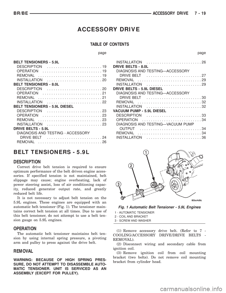
automatic belt tensioner (Fig. 1). The tensioner main-
tains correct belt tension at all times. Due to use of
this belt tensioner, do not attempt to use a belt ten-
sion gauge on 5.9L engines.
OPERATION
The automatic belt tensioner maintains belt ten-
sion by using internal spring pressure, a pivoting
arm and pulley to press against the drive belt.
REMOVAL
WARNING: BECAUSE OF HIGH SPRING PRES-
SURE, DO NOT ATTEMPT TO DISASSEMBLE AUTO-
MATIC TENSIONER. UNIT IS SERVICED AS AN
ASSEMBLY (EXCEPT FOR PULLEY).(1) Remove accessory drive belt. (Refer to 7 -
COOLING/ACCESSORY DRIVE/DRIVE BELTS -
REMOVAL).
(2) Disconnect wiring and secondary cable from
ignition coil.
(3) Remove ignition coil from coil mounting
bracket (two bolts). Do not remove coil mounting
bracket from cylinder head.
Fig. 1 Automatic Belt Tensioner - 5.9L Engines
1 - AUTOMATIC TENSIONER
2 - COIL AND BRACKET
3 - SCREW AND WASHER
BR/BEACCESSORY DRIVE 7 - 19
Page 275 of 2255
REMOVAL
NOTE: The belt routing schematics are published
from the latest information available at the time of
publication. If anything differs between these sche-
matics and the Belt Routing Label, use the sche-
matics on Belt Routing Label. This label is located
in the engine compartment.
CAUTION: Do not attempt to check belt tension with
a belt tension gauge on vehicles equipped with an
automatic belt tensioner. Refer to Automatic Belt
Tensioner in this group.
Drive belts on these engines are equipped with a
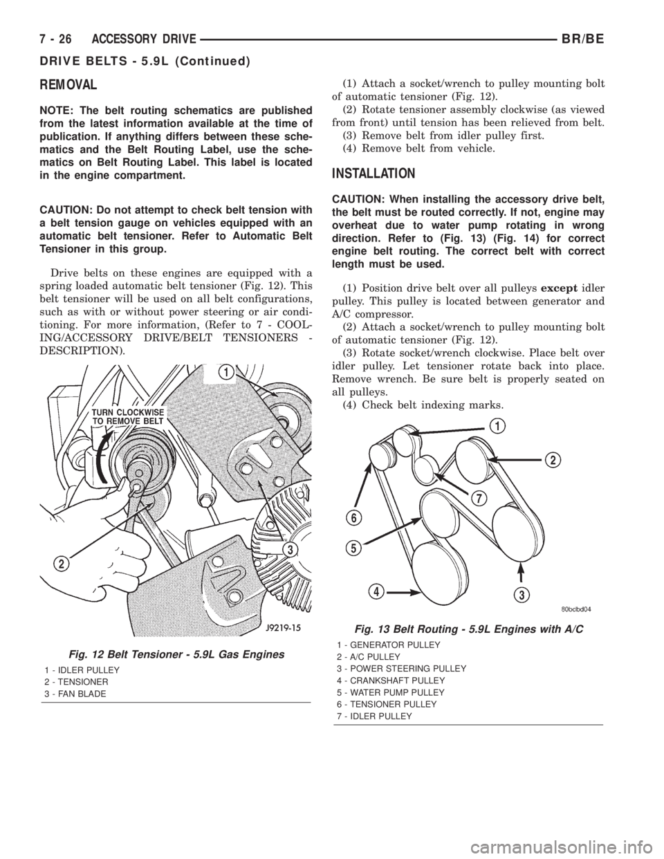
spring loaded automatic belt tensioner (Fig. 12). This
belt tensioner will be used on all belt configurations,
such as with or without power steering or air condi-
tioning. For more information, (Refer to 7 - COOL-
ING/ACCESSORY DRIVE/BELT TENSIONERS -
DESCRIPTION).(1) Attach a socket/wrench to pulley mounting bolt
of automatic tensioner (Fig. 12).
(2) Rotate tensioner assembly clockwise (as viewed
from front) until tension has been relieved from belt.
(3) Remove belt from idler pulley first.
(4) Remove belt from vehicle.
INSTALLATION
CAUTION: When installing the accessory drive belt,
the belt must be routed correctly. If not, engine may
overheat due to water pump rotating in wrong
direction. Refer to (Fig. 13) (Fig. 14) for correct
engine belt routing. The correct belt with correct
length must be used.
(1) Position drive belt over all pulleysexceptidler
pulley. This pulley is located between generator and
A/C compressor.
(2) Attach a socket/wrench to pulley mounting bolt
of automatic tensioner (Fig. 12).
(3) Rotate socket/wrench clockwise. Place belt over
idler pulley. Let tensioner rotate back into place.
Remove wrench. Be sure belt is properly seated on
all pulleys.
(4) Check belt indexing marks.
Fig. 12 Belt Tensioner - 5.9L Gas Engines
1 - IDLER PULLEY
2 - TENSIONER
3 - FAN BLADE
Fig. 13 Belt Routing - 5.9L Engines with A/C
1 - GENERATOR PULLEY
2 - A/C PULLEY
3 - POWER STEERING PULLEY
4 - CRANKSHAFT PULLEY
5 - WATER PUMP PULLEY
6 - TENSIONER PULLEY
7 - IDLER PULLEY
7 - 26 ACCESSORY DRIVEBR/BE
DRIVE BELTS - 5.9L (Continued)
Page 278 of 2255
CONDITION POSSIBLE CAUSES CORRECTION
NOISE (Objectional squeal, spueak,
or rumble is heard or felt while drive
belt is in operation)1. Incorrect belt tension 1. Inspect/Replace tensioner if
necessary
2. Bearing noise 2. Locate and repair
3. Belt misalignment 3. Align belt/pulley(s)
4. Belt to pulley mismatch 4. Install correct belt
5. Driven component induced
vibration5. Locate defective driven
component and repair
TENSION SHEETING FABRIC
FAILURE
(Woven fabric on outside,
circumference of belt has cracked or
separated from body of belt)1. Tension sheeting contacting
stationary object1. Correct rubbing condition
2. Excessive heat causing woven
fabric to age2. Replace belt
3. Tension sheeting splice has
fractured3. Replace belt
CORD EDGE FAILURE
(Tensile member exposed at edges
of belt or separated from belt body)1. Incorrect belt tension 1. Inspect/Replace tensioner if
necessary
2. Belt contacting stationary object 2. Replace belt
3. Pulley(s) out of tolerance 3. Replace pulley
4. Insufficient adhesion between
tensile member and rubber matrix4. Replace belt
REMOVAL
Drive belts are equipped with a spring loaded auto-
matic belt tensioner (Fig. 16). This belt tensioner will
be used on all belt configurations, such as with or
without power steering or air conditioning. For more
information, refer to Automatic Belt Tensioner, pro-
ceeding in this group.
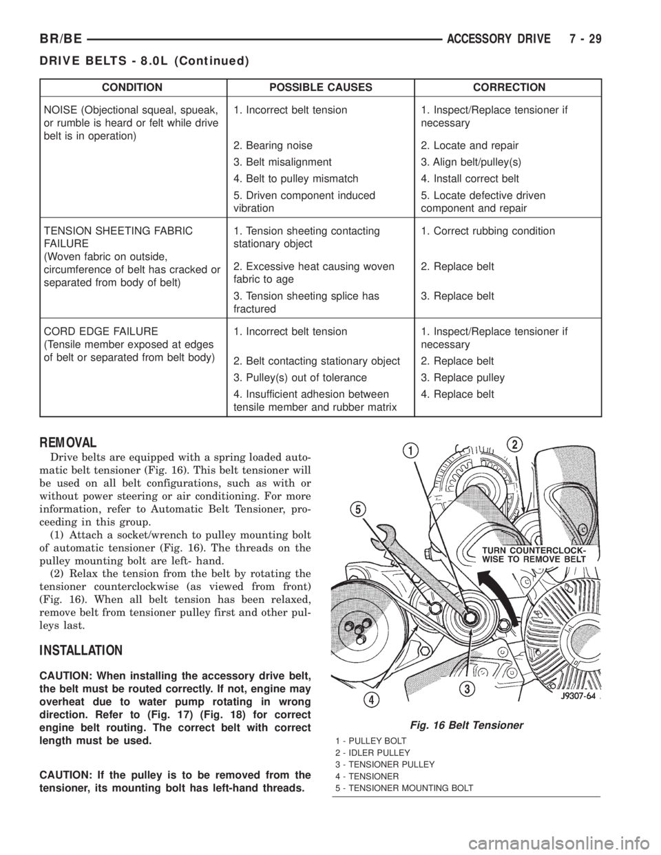
(1) Attach a socket/wrench to pulley mounting bolt
of automatic tensioner (Fig. 16). The threads on the
pulley mounting bolt are left- hand.
(2) Relax the tension from the belt by rotating the
tensioner counterclockwise (as viewed from front)
(Fig. 16). When all belt tension has been relaxed,
remove belt from tensioner pulley first and other pul-
leys last.
INSTALLATION
CAUTION: When installing the accessory drive belt,
the belt must be routed correctly. If not, engine may
overheat due to water pump rotating in wrong
direction. Refer to (Fig. 17) (Fig. 18) for correct
engine belt routing. The correct belt with correct
length must be used.
CAUTION: If the pulley is to be removed from the
tensioner, its mounting bolt has left-hand threads.
Fig. 16 Belt Tensioner
1 - PULLEY BOLT
2 - IDLER PULLEY
3 - TENSIONER PULLEY
4 - TENSIONER
5 - TENSIONER MOUNTING BOLT
BR/BEACCESSORY DRIVE 7 - 29
DRIVE BELTS - 8.0L (Continued)
Page 281 of 2255
CONDITION POSSIBLE CAUSES CORRECTION
BELT BROKEN
(Note: Identify and correct problem
before new belt is installed)1. Incorrect belt tension 1. Replace Inspect/Replace
tensioner if necessary
2. Tensile member damaged during
belt installation2. Replace belt
3. Severe misalignment 3. Align pulley(s)
4. Bracket, pulley, or bearing failure 4. Replace defective component
and belt
NOISE (Objectional squeal, spueak,
or rumble is heard or felt while drive
belt is in operation)1. Incorrect belt tension 1. Inspect/Replace tensioner if
necessary
2. Bearing noise 2. Locate and repair
3. Belt misalignment 3. Align belt/pulley(s)
4. Belt to pulley mismatch 4. Install correct belt
5. Driven component induced
vibration5. Locate defective driven
component and repair
TENSION SHEETING FABRIC
FAILURE
(Woven fabric on outside,
circumference of belt has cracked or
separated from body of belt)1. Tension sheeting contacting
stationary object1. Correct rubbing condition
2. Excessive heat causing woven
fabric to age2. Replace belt
3. Tension sheeting splice has
fractured3. Replace belt
CORD EDGE FAILURE
(Tensile member exposed at edges
of belt or separated from belt body)1. Incorrect belt tension 1. Inspect/Replace tensioner if
necessary
2. Belt contacting stationary object 2. Replace belt
3. Pulley(s) out of tolerance 3. Replace pulley
4. Insufficient adhesion between
tensile member and rubber matrix4. Replace belt
REMOVAL
CAUTION: Do not attempt to check belt tension with
a belt tension gauge on vehicles equipped with an
automatic belt tensioner. Refer to Automatic Belt
Tensioner in this group.
NOTE: The belt routing schematics are published
from the latest information available at the time of
publication. If anything differs between these sche-
matics and the Belt Routing Label, use the sche-
matics on Belt Routing Label.This label is located in
the engine compartment.
Drive belts on diesel engines are equipped with a
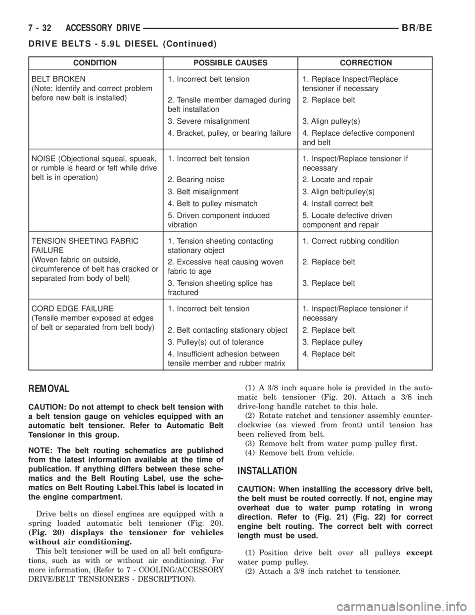
spring loaded automatic belt tensioner (Fig. 20).
(Fig. 20) displays the tensioner for vehicles
without air conditioning.
This belt tensioner will be used on all belt configura-
tions, such as with or without air conditioning. For
more information, (Refer to 7 - COOLING/ACCESSORY
DRIVE/BELT TENSIONERS - DESCRIPTION).
(1) A 3/8 inch square hole is provided in the auto-
matic belt tensioner (Fig. 20). Attach a 3/8 inch
drive-long handle ratchet to this hole.
(2) Rotate ratchet and tensioner assembly counter-
clockwise (as viewed from front) until tension has
been relieved from belt.
(3) Remove belt from water pump pulley first.
(4) Remove belt from vehicle.
INSTALLATION
CAUTION: When installing the accessory drive belt,
the belt must be routed correctly. If not, engine may
overheat due to water pump rotating in wrong
direction. Refer to (Fig. 21) (Fig. 22) for correct
engine belt routing. The correct belt with correct
length must be used.
(1) Position drive belt over all pulleysexcept
water pump pulley.
(2) Attach a 3/8 inch ratchet to tensioner.
7 - 32 ACCESSORY DRIVEBR/BE
DRIVE BELTS - 5.9L DIESEL (Continued)
Page 288 of 2255
INSTALLATION.........................64
RADIATOR PRESSURE CAP
DESCRIPTION.........................64
OPERATION...........................64
DIAGNOSIS AND TESTING
DIAGNOSIS AND TESTINGÐRADIATOR
CAP-TO-FILLER NECK SEAL.............65
DIAGNOSIS AND TESTINGÐRADIATOR
CAP................................65
CLEANING............................65
INSPECTION..........................66
WATER PUMP - 5.9L
DESCRIPTION.........................66
OPERATION...........................66
DIAGNOSIS AND TESTINGÐWATER PUMP . . . 66
REMOVAL.............................66
CLEANING............................68
INSPECTION..........................68
INSTALLATION.........................68
WATER PUMP - 8.0L
DIAGNOSIS AND TESTINGÐWATER PUMP . . . 69
REMOVAL.............................69CLEANING............................71
INSPECTION..........................71
INSTALLATION.........................71
WATER PUMP - 5.9L DIESEL
DESCRIPTION.........................72
OPERATION...........................72
DIAGNOSIS AND TESTINGÐWATER PUMP . . . 72
REMOVAL.............................72
CLEANING............................72
INSPECTION..........................72
INSTALLATION.........................72
WATER PUMP INLET TUBE - 5.9L
REMOVAL
REMOVAL - WATER PUMP BYPASS HOSE
WITH AIR CONDITIONING...............73
REMOVAL - WATER PUMP BYPASS HOSE
WITHOUT AIR CONDITIONING...........76
INSTALLATION
INSTALLATION - WATER PUMP BYPASS
HOSE WITH AIR CONDITIONING.........76
INSTALLATION - WATER PUMP BYPASS
HOSE WITHOUT AIR CONDITIONING......77
COOLANT
DESCRIPTION - ENGINE COOLANT
ETHYLENE-GLYCOL MIXTURES
CAUTION: Richer antifreeze mixtures cannot be
measured with normal field equipment and can
cause problems associated with 100 percent ethyl-
ene-glycol.
The required ethylene-glycol (antifreeze) and water
mixture depends upon the climate and vehicle oper-
ating conditions. The recommended mixture of 50/50
ethylene-glycol and water will provide protection
against freezing to -37 deg. C (-35 deg. F). The anti-
freeze concentrationmust alwaysbe a minimum of
44 percent, year-round in all climates.If percentage
is lower than 44 percent, engine parts may be
eroded by cavitation, and cooling system com-
ponents may be severely damaged by corrosion.
Maximum protection against freezing is provided
with a 68 percent antifreeze concentration, which
prevents freezing down to -67.7 deg. C (-90 deg. F). A
higher percentage will freeze at a warmer tempera-
ture. Also, a higher percentage of antifreeze can
cause the engine to overheat because the specific
heat of antifreeze is lower than that of water.
Use of 100 percent ethylene-glycol will cause for-
mation of additive deposits in the system, as the cor-
rosion inhibitive additives in ethylene-glycol requirethe presence of water to dissolve. The deposits act as
insulation, causing temperatures to rise to as high as
149 deg. C (300) deg. F). This temperature is hot
enough to melt plastic and soften solder. The
increased temperature can result in engine detona-
tion. In addition, 100 percent ethylene-glycol freezes
at 22 deg. C (-8 deg. F ).
PROPYLENE-GLYCOL MIXTURES
It's overall effective temperature range is smaller
than that of ethylene-glycol. The freeze point of 50/50
propylene-glycol and water is -32 deg. C (-26 deg. F).
5 deg. C higher than ethylene-glycol's freeze point.
The boiling point (protection against summer boil-
over) of propylene-glycol is 125 deg. C (257 deg. F )
at 96.5 kPa (14 psi), compared to 128 deg. C (263
deg. F) for ethylene-glycol. Use of propylene-glycol
can result in boil-over or freeze-up on a cooling sys-
tem designed for ethylene-glycol. Propylene glycol
also has poorer heat transfer characteristics than
ethylene glycol. This can increase cylinder head tem-
peratures under certain conditions.
Propylene-glycol/ethylene-glycol Mixtures can
cause the destabilization of various corrosion inhibi-
tors, causing damage to the various cooling system
components. Also, once ethylene-glycol and propy-
lene-glycol based coolants are mixed in the vehicle,
conventional methods of determining freeze point will
not be accurate. Both the refractive index and spe-
cific gravity differ between ethylene glycol and propy-
lene glycol.
BR/BEENGINE 7 - 39
Page 291 of 2255
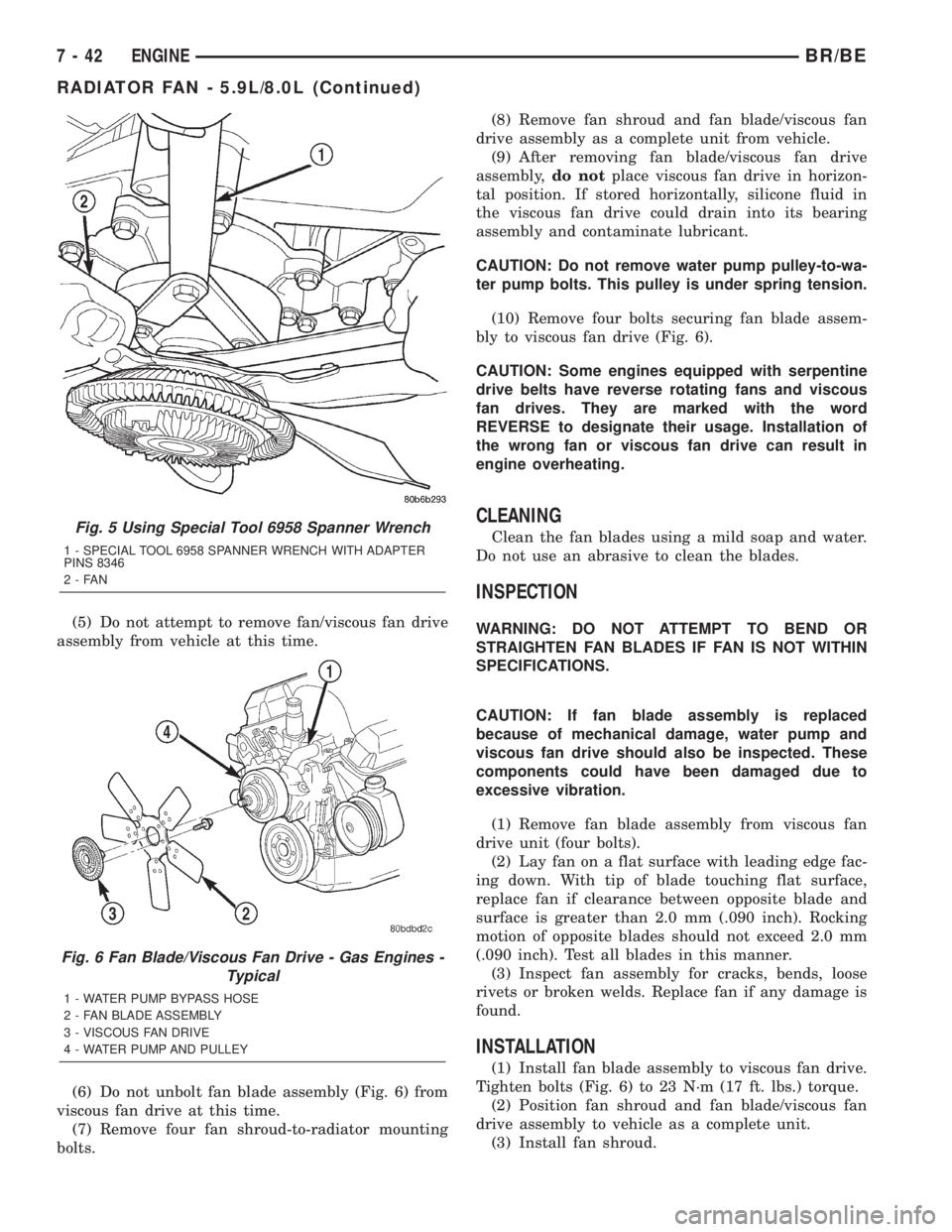
(5) Do not attempt to remove fan/viscous fan drive
assembly from vehicle at this time.
(6) Do not unbolt fan blade assembly (Fig. 6) from
viscous fan drive at this time.
(7) Remove four fan shroud-to-radiator mounting
bolts.(8) Remove fan shroud and fan blade/viscous fan
drive assembly as a complete unit from vehicle.
(9) After removing fan blade/viscous fan drive
assembly,do notplace viscous fan drive in horizon-
tal position. If stored horizontally, silicone fluid in
the viscous fan drive could drain into its bearing
assembly and contaminate lubricant.
CAUTION: Do not remove water pump pulley-to-wa-
ter pump bolts. This pulley is under spring tension.
(10) Remove four bolts securing fan blade assem-
bly to viscous fan drive (Fig. 6).
CAUTION: Some engines equipped with serpentine
drive belts have reverse rotating fans and viscous
fan drives. They are marked with the word
REVERSE to designate their usage. Installation of
the wrong fan or viscous fan drive can result in
engine overheating.
CLEANING
Clean the fan blades using a mild soap and water.
Do not use an abrasive to clean the blades.
INSPECTION
WARNING: DO NOT ATTEMPT TO BEND OR
STRAIGHTEN FAN BLADES IF FAN IS NOT WITHIN
SPECIFICATIONS.
CAUTION: If fan blade assembly is replaced
because of mechanical damage, water pump and
viscous fan drive should also be inspected. These
components could have been damaged due to
excessive vibration.
(1) Remove fan blade assembly from viscous fan
drive unit (four bolts).
(2) Lay fan on a flat surface with leading edge fac-
ing down. With tip of blade touching flat surface,
replace fan if clearance between opposite blade and
surface is greater than 2.0 mm (.090 inch). Rocking
motion of opposite blades should not exceed 2.0 mm
(.090 inch). Test all blades in this manner.
(3) Inspect fan assembly for cracks, bends, loose
rivets or broken welds. Replace fan if any damage is
found.
INSTALLATION
(1) Install fan blade assembly to viscous fan drive.
Tighten bolts (Fig. 6) to 23 N´m (17 ft. lbs.) torque.
(2) Position fan shroud and fan blade/viscous fan
drive assembly to vehicle as a complete unit.
(3) Install fan shroud.
Fig. 5 Using Special Tool 6958 Spanner Wrench
1 - SPECIAL TOOL 6958 SPANNER WRENCH WITH ADAPTER
PINS 8346
2-FAN
Fig. 6 Fan Blade/Viscous Fan Drive - Gas Engines -
Typical
1 - WATER PUMP BYPASS HOSE
2 - FAN BLADE ASSEMBLY
3 - VISCOUS FAN DRIVE
4 - WATER PUMP AND PULLEY
7 - 42 ENGINEBR/BE
RADIATOR FAN - 5.9L/8.0L (Continued)
Page 292 of 2255
(4) Install fan blade/viscous fan drive assembly to
water pump shaft (Fig. 6).
(5) Except 8.0L V-10 Engine: Install coolant
reserve/overflow tank to fan shroud. Snaps into posi-
tion.
(6) Install throttle cable to fan shroud.
(7) Connect negative battery cable.
NOTE:
Viscous Fan Drive Fluid Pump Out Requirement:
After installing a new viscous fan drive, bring the
engine speed up to approximately 2000 rpm and
hold for approximately two minutes. This will
ensure proper fluid distribution within the drive.
RADIATOR FAN - 5.9L DIESEL
REMOVAL
CAUTION: If the viscous fan drive is replaced
because of mechanical damage, the cooling fan
blades should also be inspected. Inspect for fatigue
cracks, loose blades, or loose rivets that could
have resulted from excessive vibration. Replace fan
blade assembly if any of these conditions are
found. Also inspect water pump bearing and shaft
assembly for any related damage due to a viscous
fan drive malfunction.
(1) Disconnect the battery negative cables.
(2) Remove the fan shroud mounting bolts. Posi-
tion fan shroud towards engine.
CAUTION: Do not remove the fan pulley bolts. This
pulley is under spring tension.
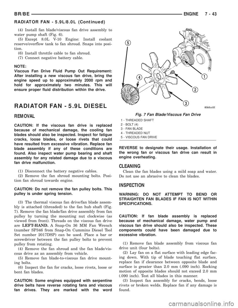
(3) The thermal viscous fan drive/fan blade assem-
bly is attached (threaded) to the fan hub shaft (Fig.
7). Remove the fan blade/fan drive assembly from fan
pulley by turning the mounting nut clockwise (as
viewed from front). Threads on the viscous fan drive
areLEFT-HAND.A Snap-On 36 MM Fan Wrench
(number SP346 from Snap-On Cummins Diesel Tool
Set number 2017DSP) can be used. Place a bar or
screwdriver between the fan pulley bolts to prevent
pulley from rotating.
(4) Remove the fan shroud and the fan blade/vis-
cous drive as an assembly from vehicle.
(5) Remove fan blade-to-viscous fan drive mount-
ing bolts.
(6) Inspect the fan for cracks, loose rivets, loose or
bent fan blades.
CAUTION: Some engines equipped with serpentine
drive belts have reverse rotating fans and viscous
fan drives. They are marked with the wordREVERSE to designate their usage. Installation of
the wrong fan or viscous fan drive can result in
engine overheating.
CLEANING
Clean the fan blades using a mild soap and water.
Do not use an abrasive to clean the blades.
INSPECTION
WARNING: DO NOT ATTEMPT TO BEND OR
STRAIGHTEN FAN BLADES IF FAN IS NOT WITHIN
SPECIFICATIONS.
CAUTION: If fan blade assembly is replaced
because of mechanical damage, water pump and
viscous fan drive should also be inspected. These
components could have been damaged due to
excessive vibration.
(1) Remove fan blade assembly from viscous fan
drive unit (four bolts).
(2) Lay fan on a flat surface with leading edge fac-
ing down. With tip of blade touching flat surface,
replace fan if clearance between opposite blade and
surface is greater than 2.0 mm (.090 inch). Rocking
motion of opposite blades should not exceed 2.0 mm
(.090 inch). Test all blades in this manner.
(3) Inspect fan assembly for cracks, bends, loose
rivets or broken welds. Replace fan if any damage is
found.
Fig. 7 Fan Blade/Viscous Fan Drive
1 - THREADED SHAFT
2 - BOLT (4)
3 - FAN BLADE
4 - THREADED NUT
5 - VISCOUS FAN DRIVE
BR/BEENGINE 7 - 43
RADIATOR FAN - 5.9L/8.0L (Continued)
Page 299 of 2255
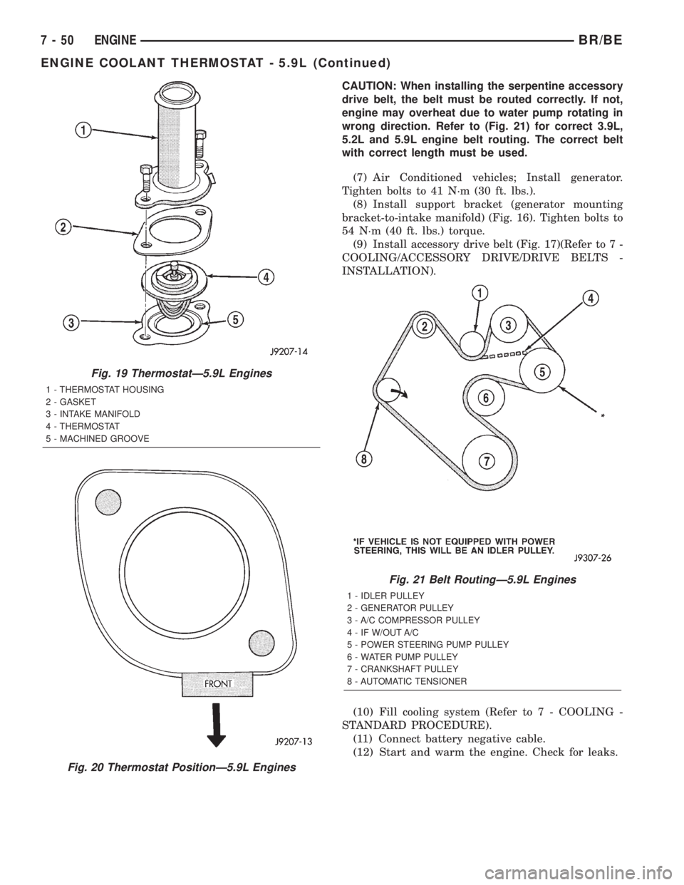
CAUTION: When installing the serpentine accessory
drive belt, the belt must be routed correctly. If not,
engine may overheat due to water pump rotating in
wrong direction. Refer to (Fig. 21) for correct 3.9L,
5.2L and 5.9L engine belt routing. The correct belt
with correct length must be used.
(7) Air Conditioned vehicles; Install generator.
Tighten bolts to 41 N´m (30 ft. lbs.).
(8) Install support bracket (generator mounting
bracket-to-intake manifold) (Fig. 16). Tighten bolts to
54 N´m (40 ft. lbs.) torque.
(9) Install accessory drive belt (Fig. 17)(Refer to 7 -
COOLING/ACCESSORY DRIVE/DRIVE BELTS -
INSTALLATION).
(10) Fill cooling system (Refer to 7 - COOLING -
STANDARD PROCEDURE).
(11) Connect battery negative cable.
(12) Start and warm the engine. Check for leaks.
Fig. 19 ThermostatÐ5.9L Engines
1 - THERMOSTAT HOUSING
2 - GASKET
3 - INTAKE MANIFOLD
4 - THERMOSTAT
5 - MACHINED GROOVE
Fig. 20 Thermostat PositionÐ5.9L Engines
Fig. 21 Belt RoutingÐ5.9L Engines
1 - IDLER PULLEY
2 - GENERATOR PULLEY
3 - A/C COMPRESSOR PULLEY
4 - IF W/OUT A/C
5 - POWER STEERING PUMP PULLEY
6 - WATER PUMP PULLEY
7 - CRANKSHAFT PULLEY
8 - AUTOMATIC TENSIONER
7 - 50 ENGINEBR/BE
ENGINE COOLANT THERMOSTAT - 5.9L (Continued)