2002 DODGE RAM engine overheat
[x] Cancel search: engine overheatPage 302 of 2255

(4) Install thermostat into recessed machined
groove on intake manifold (Fig. 25).
(5) Install thermostat housing (Fig. 25).
(6) Install housing-to-intake manifold bolts.
Tighten bolts to 25 N´m (220 in. lbs.) torque.
CAUTION: Housing bolts should be tightened
evenly to prevent damage to housing and to pre-
vent leaks.
(7) Connect the wiring to both sensors.
(8) Install the upper radiator hose and hose clamp
to thermostat housing.
(9) Install support rod.
(10) Fill cooling system (Refer to 7 - COOLING -
STANDARD PROCEDURE).
(11) Connect negative battery cable to battery.
(12) Start and warm engine. Check for leaks.
ENGINE COOLANT
THERMOSTAT - 5.9L DIESEL
DESCRIPTION
CAUTION: Do not operate an engine without a ther-
mostat, except for servicing or testing. An engine
with the thermostat removed will operate in the
radiator bypass mode, causing an overheat condi-
tion.
The thermostat of the 5.9L diesel engine is located
in the front of the cylinder head, underneath the
water outlet connector (Fig. 26).
The same thermostat is used for winter and sum-
mer seasons. An engine should not be operated with-
out a thermostat, except for servicing or testing.
Operating without a thermostat causes longer engine
warmup time, unreliable warmup performance,
increased exhaust emissions and crankcase condensa-
tion that can result in sludge formation.
OPERATION
The wax pellet is located in a sealed container at
the spring end of the thermostat. When heated, the
pellet expands, overcoming closing spring tension
and water pump pressure to force the valve to open.
DIAGNOSIS AND TESTINGÐTHERMOSTAT
The cooling system used with the diesel engine
provides the extra coolant capacity and extra cooling
protection needed for higher GVWR (Gross Vehicle
Weight Rating) and GCWR (Gross Combined Weight
Rating) vehicles.
This system capacity will not effect warm up or
cold weather operating characteristics if the thermo-stat is operating properly. This is because coolant
will be held in the engine until it reaches the ther-
mostat ªsetº temperature.
Diesel engines, due to their inherent efficiency are
slower to warm up than gasoline powered engines,
and will operate at lower temperatures when the
vehicle is unloaded. Because of this, lower tempera-
ture gauge readings for diesel versus gasoline
engines may, at times be normal.
Typically, complaints of low engine coolant temper-
ature are observed as low heater output when com-
bined with cool or cold outside temperatures.
To help promote faster engine warm-up, the elec-
tric engine block heater must be used with cool or
cold outside temperatures. This will help keep the
engine coolant warm when the vehicle is parked. Use
the block heater if the outside temperature is below
4ÉC (40ÉF).Do not use the block heater if the
outside temperature is above 4ÉC (40ÉF).
A ªCold Weather Coverº is available from the parts
department through the Mopar Accessories product
line. This accessory cover is designed to block airflow
entering the radiator and engine compartment to
promote faster engine warm-up. It attaches to the
front of the vehicle at the grill opening.The cover is
to be used with cool or cold temperatures only.
If used with high outside temperatures, serious
engine damage could result.Refer to the litera-
ture supplied with the cover for additional informa-
tion.
Fig. 26 ThermostatÐ5.9L DieselÐTypical
1 - WATER OUTLET CONNECTOR
2 - THERMOSTAT HOUSING
3 - THERMOSTAT
BR/BEENGINE 7 - 53
ENGINE COOLANT THERMOSTAT - 8.0L (Continued)
Page 305 of 2255

(1) Drill a 3.18-mm (1/8-in) diameter hole in the
top center of the fan shroud.
(2) Obtain a dial thermometer with an 8 inch stem
(or equivalent). It should have a range of -18É-to-
105ÉC (0É-to-220É F). Insert thermometer through the
hole in the shroud. Be sure that there is adequate
clearance from the fan blades.
(3) Connect a tachometer and an engine ignition
timing light. The timing light is to be used as a
strobe light. This step cannot be used on the diesel
engine.
(4) Block the air flow through the radiator. Secure
a sheet of plastic in front of the radiator (or air con-
ditioner condenser). Use tape at the top to secure the
plastic and be sure that the air flow is blocked.
(5) Be sure that the air conditioner (if equipped) is
turned off.
WARNING: USE EXTREME CAUTION WHEN THE
ENGINE IS OPERATING. DO NOT STAND IN A
DIRECT LINE WITH THE FAN. DO NOT PUT YOUR
HANDS NEAR THE PULLEYS, BELTS OR FAN. DO
NOT WEAR LOOSE CLOTHING.
(6) Start the engine and operate at 2400 rpm.
Within ten minutes the air temperature (indicated on
the dial thermometer) should be up to 88É C (190É F).
Fan driveengagementshould start to occur at/be-
tween:
²5.9L gas engines Ð 79É C (175É F)
²8.0L engine Ð 88É to 96É C (190É to 205É F)
²5.9L diesel engine Ð 71É to 82É C (160É to 179É
F) Engagement is distinguishable by a definite
increasein fan flow noise (roaring). The timing light
also will indicate an increase in the speed of the fan
(non-diesel only).
(7) When viscous drive engagement is verified,
remove the plastic sheet. Fan drivedisengagement
should start to occur at between 57É to 79É C (135É to
175É F). A definitedecreaseof fan flow noise (roar-
ing) should be noticed. If not, replace the defective
viscous fan drive unit.
CAUTION: Some engines equipped with serpentine
drive belts have reverse rotating fans and viscous
fan drives. They are marked with the word
REVERSE to designate their usage. Installation of
the wrong fan or viscous fan drive can result in
engine overheating.
CAUTION: If the viscous fan drive is replaced
because of mechanical damage, the cooling fan
blades should also be inspected. Inspect for fatigue
cracks, loose blades, or loose rivets that could
have resulted from excessive vibration. Replace fan
blade assembly if any of these conditions arefound. Also inspect water pump bearing and shaft
assembly for any related damage due to a viscous
fan drive malfunction.
FAN DRIVE VISCOUS CLUTCH
- 5.9L DIESEL
DESCRIPTION
The thermal viscous fan drive (Fig. 30) is a sili-
cone-fluid- filled coupling used to connect the fan
blades to the water pump shaft. The coupling allows
the fan to be driven in a normal manner. This is
done at low engine speeds while limiting the top
speed of the fan to a predetermined maximum level
at higher engine speeds.
OPERATION
A thermostatic bimetallic spring coil is located on
the front face of the viscous fan drive unit (a typical
viscous unit is shown in (Fig. 31). This spring coil
reacts to the temperature of the radiator discharge
air. It engages the viscous fan drive for higher fan
speed if the air temperature from the radiator rises
above a certain point. Until additional engine cooling
is necessary, the fan will remain at a reduced rpm
regardless of engine speed.
Only when sufficient heat is present, will the vis-
cous fan drive engage. This is when the air flowing
through the radiator core causes a reaction to the
Fig. 30 Viscous Fan
1 - THREADED SHAFT
2 - BOLT (4)
3 - FAN BLADE
4 - THREADED NUT
5 - VISCOUS FAN DRIVE
7 - 56 ENGINEBR/BE
FAN DRIVE VISCOUS CLUTCH - 5.9L/8.0L (Continued)
Page 307 of 2255

CAUTION: Some engines equipped with serpentine
drive belts have reverse rotating fans and viscous
fan drives. They are marked with the word
REVERSE to designate their usage. Installation of
the wrong fan or viscous fan drive can result in
engine overheating.
CAUTION: If the viscous fan drive is replaced
because of mechanical damage, the cooling fan
blades should also be inspected. Inspect for fatigue
cracks, loose blades, or loose rivets that could
have resulted from excessive vibration. Replace fan
blade assembly if any of these conditions are
found. Also inspect water pump bearing and shaft
assembly for any related damage due to a viscous
fan drive malfunction.
RADIATOR - 5.9L
DESCRIPTION
The radiator is a aluminum cross-flow design with
horizontal tubes through the radiator core and verti-
cal plastic side tanks (Fig. 32).
This radiator contains an internal transmission oil
cooler only on the V-10 gas engine and the 5.9L die-
sel engine combinations.
OPERATION
The radiator supplies sufficient heat transfer using
the cooling fins interlaced between the horizontal
tubes in the radiator core to cool the engine.
DIAGNOSIS AND TESTINGÐRADIATOR
COOLANT FLOW
Use the following procedure to determine if coolant
is flowing through the cooling system.
(1) Idle engine until operating temperature is
reached. If the upper radiator hose is warm to the
touch, the thermostat is opening and coolant is flow-
ing to the radiator.
WARNING: HOT, PRESSURIZED COOLANT CAN
CAUSE INJURY BY SCALDING. USING A RAG TO
COVER THE RADIATOR PRESSURE CAP, OPEN
RADIATOR CAP SLOWLY TO THE FIRST STOP. THIS
WILL ALLOW ANY BUILT-UP PRESSURE TO VENT
TO THE RESERVE/OVERFLOW TANK. AFTER PRES-
SURE BUILD-UP HAS BEEN RELEASED, REMOVE
CAP FROM FILLER NECK.
(2) Drain a small amount of coolant from the radi-
ator until the ends of the radiator tubes are visible
through the filler neck. Idle the engine at normal
operating temperature. If coolant is flowing past the
exposed tubes, the coolant is circulating.
REMOVAL
(1) Disconnect battery negative cables.
WARNING: DO NOT REMOVE THE CYLINDER
BLOCK DRAIN PLUGS OR LOOSEN THE RADIATOR
DRAINCOCK WITH THE SYSTEM HOT AND UNDER
PRESSURE. SERIOUS BURNS FROM COOLANT
CAN OCCUR.
(2) Drain the cooling system (Refer to 7 - COOL-
ING - STANDARD PROCEDURE).
WARNING: CONSTANT TENSION HOSE CLAMPS
ARE USED ON MOST COOLING SYSTEM HOSES.
WHEN REMOVING OR INSTALLING, USE ONLY
TOOLS DESIGNED FOR SERVICING THIS TYPE OF
CLAMP, SUCH AS SPECIAL CLAMP TOOL (NUMBER
6094). SNAP-ON CLAMP TOOL (NUMBER HPC-20)
MAY BE USED FOR LARGER CLAMPS. ALWAYS
WEAR SAFETY GLASSES WHEN SERVICING CON-
STANT TENSION CLAMPS.
CAUTION: A number or letter is stamped into the
tongue of constant tension clamps. If replacement
is necessary, use only an original equipment clamp
with a matching number or letter.
Fig. 32 Cross Flow RadiatorÐTypical
1 - COOLING TUBES
2 - TANKS
7 - 58 ENGINEBR/BE
FAN DRIVE VISCOUS CLUTCH - 5.9L DIESEL (Continued)
Page 326 of 2255

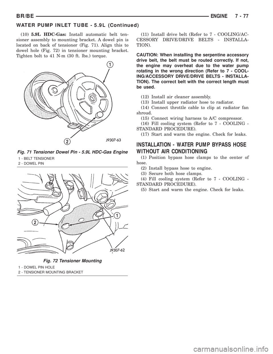
(10)5.9L HDC-Gas:Install automatic belt ten-
sioner assembly to mounting bracket. A dowel pin is
located on back of tensioner (Fig. 71). Align this to
dowel hole (Fig. 72) in tensioner mounting bracket.
Tighten bolt to 41 N´m (30 ft. lbs.) torque.(11) Install drive belt (Refer to 7 - COOLING/AC-
CESSORY DRIVE/DRIVE BELTS - INSTALLA-
TION).
CAUTION: When installing the serpentine accessory
drive belt, the belt must be routed correctly. If not,
the engine may overheat due to the water pump
rotating in the wrong direction (Refer to 7 - COOL-
ING/ACCESSORY DRIVE/DRIVE BELTS - INSTALLA-
TION). The correct belt with the correct length must
be used.
(12) Install air cleaner assembly.
(13) Install upper radiator hose to radiator.
(14) Connect throttle cable to clip at radiator fan
shroud.
(15) Connect wiring harness to A/C compressor.
(16) Fill cooling system (Refer to 7 - COOLING -
STANDARD PROCEDURE).
(17) Start and warm the engine. Check for leaks.
INSTALLATION - WATER PUMP BYPASS HOSE
WITHOUT AIR CONDITIONING
(1) Position bypass hose clamps to the center of
hose.
(2) Install bypass hose to engine.
(3) Secure both hose clamps.
(4) Fill cooling system (Refer to 7 - COOLING -
STANDARD PROCEDURE).
(5) Start and warm the engine. Check for leaks.
Fig. 71 Tensioner Dowel Pin - 5.9L HDC-Gas Engine
1 - BELT TENSIONER
2 - DOWEL PIN
Fig. 72 Tensioner Mounting
1 - DOWEL PIN HOLE
2 - TENSIONER MOUNTING BRACKET
BR/BEENGINE 7 - 77
WATER PUMP INLET TUBE - 5.9L (Continued)
Page 419 of 2255

INSTALLATION
(1) Position generator to engine and snap field
wire connector into rear of generator.
(2) Install B+ terminal eyelet to generator stud.
Tighten mounting nut to 12 N´m (108 in. lbs.) torque.
(3) Install generator mounting fasteners and
tighten as follows:
²Generator mounting boltÐAll gas powered
enginesÐ41 N´m (30 ft. lbs.) torque.
²Generator pivot bolt/nutÐAll gas powered
enginesÐ41 N´m (30 ft. lbs.) torque.
²Generator mounting boltÐDiesel powered
enginesÐ54 N´m (40 ft. lbs.) torque.
²Generator pivot bolt/nutÐDiesel powered
enginesÐ54 N´m (40 ft. lbs.) torque.
CAUTION: Never force a belt over a pulley rim
using a screwdriver. The synthetic fiber of the belt
can be damaged.
CAUTION: When installing a serpentine accessory
drive belt, the belt MUST be routed correctly. The
water pump will be rotating in the wrong direction if
the belt is installed incorrectly, causing the engine
to overheat. Refer to belt routing label in engine
compartment, or refer to Belt Schematics in Group
7, Cooling System.
(4) Install generator drive belt. Refer to 7, Cooling
System for procedure.
(5) Install negative battery cable(s) to battery(s).
VOLTAGE REGULATOR
DESCRIPTION
The Electronic Voltage Regulator (EVR) is not a
separate component. It is actually a voltage regulat-
ing circuit located within the Powertrain Control
Module (PCM). The EVR is not serviced separately. If
replacement is necessary, the PCM must be replaced.
OPERATION
The amount of direct current produced by the gen-
erator is controlled by EVR circuitry contained
within the PCM. This circuitry is connected in series
with the generators second rotor field terminal and
its ground.
Voltage is regulated by cycling the ground path to
control the strength of the rotor magnetic field. The
EVR circuitry monitors system line voltage (B+) and
battery temperature (refer to Battery Temperature
Sensor for more information). It then determines a
target charging voltage. If sensed battery voltage is
0.5 volts or lower than the target voltage, the PCM
grounds the field winding until sensed battery volt-
age is 0.5 volts above target voltage. A circuit in the
PCM cycles the ground side of the generator field up
to 100 times per second (100Hz), but has the capabil-
ity to ground the field control wire 100% of the time
(full field) to achieve the target voltage. If the charg-
ing rate cannot be monitored (limp-in), a duty cycle
of 25% is used by the PCM in order to have some
generator output. Also refer to Charging System
Operation for additional information.
8F - 30 CHARGINGBR/BE
GENERATOR (Continued)
Page 476 of 2255

SPARK PLUG OVERHEATING
Overheating is indicated by a white or gray center
electrode insulator that also appears blistered (Fig.
34). The increase in electrode gap will be consider-
ably in excess of 0.001 inch per 2000 miles of opera-
tion. This suggests that a plug with a cooler heat
range rating should be used. Over advanced ignition
timing, detonation and cooling system malfunctions
can also cause spark plug overheating.
REMOVAL
On 5.9L engines, spark plug cable heat shields are
pressed into the cylinder head to surround each cable
boot and spark plug (Fig. 35).
(1) Always remove spark plug or ignition coil
cables by grasping at the cable boot (Fig. 37). Turn
the cable boot 1/2 turn and pull straight back in a
steady motion. Never pull directly on the cable.
Internal damage to cable will result.
Fig. 32 Chipped Electrode Insulator
1 - GROUND ELECTRODE
2 - CENTER ELECTRODE
3 - CHIPPED INSULATOR
Fig. 33 Preignition Damage
1 - GROUND ELECTRODE STARTING TO DISSOLVE
2 - CENTER ELECTRODE DISSOLVED
Fig. 34 Spark Plug Overheating
1 - BLISTERED WHITE OR GRAY COLORED INSULATOR
Fig. 35 Heat ShieldsÐ5.9L Engines
1 - AIR GAP
2 - SPARK PLUG BOOT HEAT SHIELD
BR/BEIGNITION CONTROL 8I - 19
SPARK PLUG (Continued)
Page 1096 of 2255

OPERATION
OPERATIONÐCYLINDER HEAD
The cylinder head closes the combustion chamber
allowing the pistons to compress the air fuel mixture
to the correct ratio for ignition. The valves located in
the cylinder head open and close to either allow clean
air into the combustion chamber or to allow the
exhaust gases out, depending on the stroke of the
engine.
OPERATION - CYLINDER HEAD COVER
GASKET
The steel-backed silicone gasket is designed to seal
the cylinder head cover for long periods of time
through extensive heat and cold, without failure. The
gasket is designed to be reusable.
DIAGNOSIS AND TESTINGÐCYLINDER HEAD
GASKET FAILURE
A cylinder head gasket leak can be located between
adjacent cylinders or between a cylinder and the
adjacent water jacket.
²Possible indications of the cylinder head gasket
leaking between adjacent cylinders are:
²Loss of engine power
²Engine misfiring
²Poor fuel economy
²Possible indications of the cylinder head gasket
leaking between a cylinder and an adjacent water
jacket are:
²Engine overheating
²Loss of coolant
²Excessive steam (white smoke) emitting from
exhaust
²Coolant foaming
CYLINDER-TO-CYLINDER LEAKAGE TEST
To determine if an engine cylinder head gasket is
leaking between adjacent cylinders, follow the proce-
dures in Cylinder Compression Pressure Test in this
section. An engine cylinder head gasket leaking
between adjacent cylinders will result in approxi-
mately a 50±70% reduction in compression pressure.
CYLINDER-TO-WATER JACKET LEAKAGE TEST
WARNING: USE EXTREME CAUTION WHEN THE
ENGINE IS OPERATING WITH COOLANT PRES-
SURE CAP REMOVED.
VISUAL TEST METHOD
With the engine cool, remove the coolant pressure
cap. Start the engine and allow it to warm up until
thermostat opens.If a large combustion/compression pressure leak
exists, bubbles will be visible in the coolant.
COOLING SYSTEM TESTER METHOD
WARNING: WITH COOLING SYSTEM TESTER IN
PLACE, PRESSURE WILL BUILD UP FAST. EXCES-
SIVE PRESSURE BUILT UP, BY CONTINUOUS
ENGINE OPERATION, MUST BE RELEASED TO A
SAFE PRESSURE POINT. NEVER PERMIT PRES-
SURE TO EXCEED 138 kPa (20 psi).
Install Cooling System Tester 7700 or equivalent to
pressure cap neck. Start the engine and observe the
tester's pressure gauge. If gauge pulsates with every
power stroke of a cylinder a combustion pressure
leak is evident.
CHEMICAL TEST METHOD
Combustion leaks into the cooling system can also
be checked by using Bloc-Chek Kit C-3685-A or
equivalent. Perform test following the procedures
supplied with the tool kit.
REMOVAL
(1) Disconnect the battery negative cable.
(2) Drain cooling system (Refer to 7 - COOLING -
STANDARD PROCEDURE).
(3) Remove the air cleaner resonator and duct
work.
(4) Remove the intake manifold-to-generator
bracket support rod. Remove the generator.
(5) Remove closed crankcase ventilation system.
(6) Disconnect the evaporation control system.
(7) Perform the Fuel System Pressure Release pro-
cedure (Refer to 14 - FUEL SYSTEM/FUEL DELIV-
ERY - STANDARD PROCEDURE). Disconnect the
fuel supply line (Refer to 14 - FUEL SYSTEM/FUEL
DELIVERY/QUICK CONNECT FITTING - STAN-
DARD PROCEDURE).
(8) Disconnect accelerator linkage and if so
equipped, the speed control and transmission kick-
down cables.
(9) Remove distributor cap and wires.
(10) Disconnect the coil wires.
(11) Disconnect heat indicator sending unit wire.
(12) Disconnect heater hoses and bypass hose.
(13) Remove cylinder head covers and gaskets
(Refer to 9 - ENGINE/CYLINDER HEAD/CYLIN-
DER HEAD COVER(S) - REMOVAL).
(14) Remove intake manifold (Refer to 9 -
ENGINE/MANIFOLDS/INTAKE MANIFOLD -
REMOVAL) and throttle body as an assembly. Dis-
card the flange side gaskets and the front and rear
cross-over gaskets.
BR/BEENGINE 5.9L 9 - 21
CYLINDER HEAD (Continued)
Page 1151 of 2255

CYLINDER HEAD
DESCRIPTION
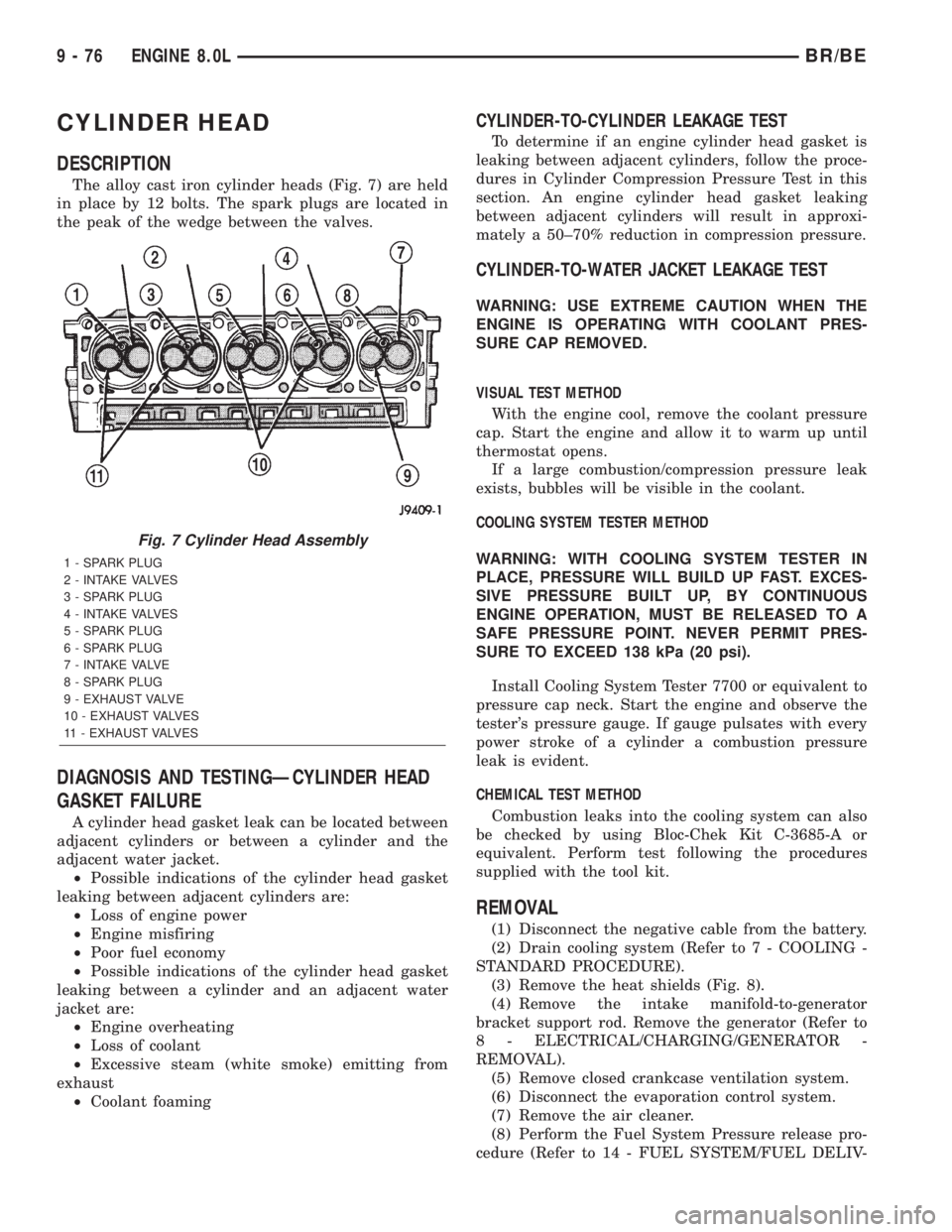
The alloy cast iron cylinder heads (Fig. 7) are held
in place by 12 bolts. The spark plugs are located in
the peak of the wedge between the valves.
DIAGNOSIS AND TESTINGÐCYLINDER HEAD
GASKET FAILURE
A cylinder head gasket leak can be located between
adjacent cylinders or between a cylinder and the
adjacent water jacket.
²Possible indications of the cylinder head gasket
leaking between adjacent cylinders are:
²Loss of engine power
²Engine misfiring
²Poor fuel economy
²Possible indications of the cylinder head gasket
leaking between a cylinder and an adjacent water
jacket are:
²Engine overheating
²Loss of coolant
²Excessive steam (white smoke) emitting from
exhaust
²Coolant foaming
CYLINDER-TO-CYLINDER LEAKAGE TEST
To determine if an engine cylinder head gasket is
leaking between adjacent cylinders, follow the proce-
dures in Cylinder Compression Pressure Test in this
section. An engine cylinder head gasket leaking
between adjacent cylinders will result in approxi-
mately a 50±70% reduction in compression pressure.
CYLINDER-TO-WATER JACKET LEAKAGE TEST
WARNING: USE EXTREME CAUTION WHEN THE
ENGINE IS OPERATING WITH COOLANT PRES-
SURE CAP REMOVED.
VISUAL TEST METHOD
With the engine cool, remove the coolant pressure
cap. Start the engine and allow it to warm up until
thermostat opens.
If a large combustion/compression pressure leak
exists, bubbles will be visible in the coolant.
COOLING SYSTEM TESTER METHOD
WARNING: WITH COOLING SYSTEM TESTER IN
PLACE, PRESSURE WILL BUILD UP FAST. EXCES-
SIVE PRESSURE BUILT UP, BY CONTINUOUS
ENGINE OPERATION, MUST BE RELEASED TO A
SAFE PRESSURE POINT. NEVER PERMIT PRES-
SURE TO EXCEED 138 kPa (20 psi).
Install Cooling System Tester 7700 or equivalent to
pressure cap neck. Start the engine and observe the
tester's pressure gauge. If gauge pulsates with every
power stroke of a cylinder a combustion pressure
leak is evident.
CHEMICAL TEST METHOD
Combustion leaks into the cooling system can also
be checked by using Bloc-Chek Kit C-3685-A or
equivalent. Perform test following the procedures
supplied with the tool kit.
REMOVAL
(1) Disconnect the negative cable from the battery.
(2) Drain cooling system (Refer to 7 - COOLING -
STANDARD PROCEDURE).
(3) Remove the heat shields (Fig. 8).
(4) Remove the intake manifold-to-generator
bracket support rod. Remove the generator (Refer to
8 - ELECTRICAL/CHARGING/GENERATOR -
REMOVAL).
(5) Remove closed crankcase ventilation system.
(6) Disconnect the evaporation control system.
(7) Remove the air cleaner.
(8) Perform the Fuel System Pressure release pro-
cedure (Refer to 14 - FUEL SYSTEM/FUEL DELIV-
Fig. 7 Cylinder Head Assembly
1 - SPARK PLUG
2 - INTAKE VALVES
3 - SPARK PLUG
4 - INTAKE VALVES
5 - SPARK PLUG
6 - SPARK PLUG
7 - INTAKE VALVE
8 - SPARK PLUG
9 - EXHAUST VALVE
10 - EXHAUST VALVES
11 - EXHAUST VALVES
9 - 76 ENGINE 8.0LBR/BE