2002 DODGE RAM engine overheat
[x] Cancel search: engine overheatPage 1781 of 2255
sludge and/or debris. The torque converter should
also be replaced at the same time.
Failure to flush the cooler and lines will result in
recontamination. Flushing applies to auxiliary cool-
ers as well. The torque converter should also be
replaced whenever a failure generates sludge and
debris. This is necessary because normal converter
flushing procedures will not remove all contami-
nants.
STANDARD PROCEDURE
STANDARD PROCEDURE - FLUID LEVEL
CHECK
Low fluid level can cause a variety of conditions
because it allows the pump to take in air along with
the fluid. As in any hydraulic system, air bubbles
make the fluid spongy, therefore, pressures will be
low and build up slowly.
Improper filling can also raise the fluid level too
high. When the transmssion has too much fluid, the
geartrain churns up foam and cause the same condi-
tions which occur with a low fluid level.
In either case, air bubbles can cause overheating
and/or fluid oxidation, and varnishing. This can
interfere with normal valve, clutch, and accumulator
operation. Foaming can also result in fluid escaping
from the transmission vent where it may be mis-
taken for a leak.
Along with fluid level, it is important to check the
condition of the fluid. When the fluid smells burned,
and is contaminated with metal or friction material
particles, a complete transmission recondition is
needed. Be sure to examine the fluid on the dipstick
closely. If there is any doubt about its condition,
drain out a sample for a double check.
After the fluid has been checked, seat the dipstick
fully to seal out water and dirt.
The transmission has a dipstick to check oil level.
It is located on the right side of the engine. Be sure
to wipe all dirt from dipstick handle before removing.
Fluid level is checked with the engine running at
curb idle speed, the transmission in NEUTRAL and
the transmission fluid at normal operating tempera-
ture.The engine should be running at idle
speed for at least one minute, with the vehicle
on level ground.
The transmission fluid level can be checked two
ways.
PROCEDURE ONE
(1) Transmission fluid must be at normal operat-
ing temperature for accurate fluid level check. Drive
vehicle if necessary to bring fluid temperature up to
normal hot operating temperature of 82ÉC (180ÉF).(2) Position vehicle on level surface.
(3) Start and run engine at curb idle speed.
(4) Apply parking brakes.
(5) Shift transmission momentarily into all gear
ranges. Then shift transmission back to NEUTRAL.
(6) Clean top of filler tube and dipstick to keep
dirt from entering tube.
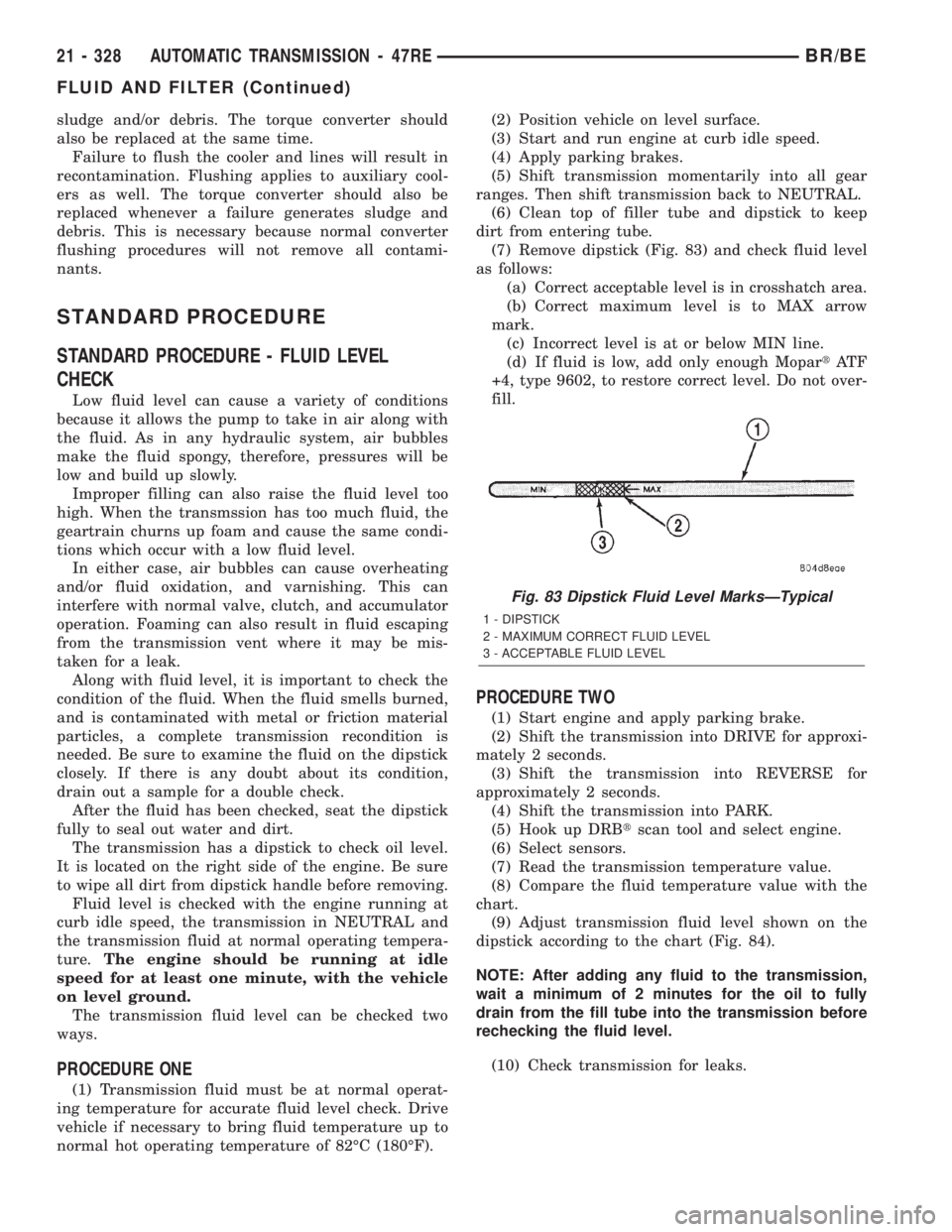
(7) Remove dipstick (Fig. 83) and check fluid level
as follows:
(a) Correct acceptable level is in crosshatch area.
(b) Correct maximum level is to MAX arrow
mark.
(c) Incorrect level is at or below MIN line.
(d) If fluid is low, add only enough MopartAT F
+4, type 9602, to restore correct level. Do not over-
fill.
PROCEDURE TWO
(1) Start engine and apply parking brake.
(2) Shift the transmission into DRIVE for approxi-
mately 2 seconds.
(3) Shift the transmission into REVERSE for
approximately 2 seconds.
(4) Shift the transmission into PARK.
(5) Hook up DRBtscan tool and select engine.
(6) Select sensors.
(7) Read the transmission temperature value.
(8) Compare the fluid temperature value with the
chart.
(9) Adjust transmission fluid level shown on the
dipstick according to the chart (Fig. 84).
NOTE: After adding any fluid to the transmission,
wait a minimum of 2 minutes for the oil to fully
drain from the fill tube into the transmission before
rechecking the fluid level.
(10) Check transmission for leaks.
Fig. 83 Dipstick Fluid Level MarksÐTypical
1 - DIPSTICK
2 - MAXIMUM CORRECT FLUID LEVEL
3 - ACCEPTABLE FLUID LEVEL
21 - 328 AUTOMATIC TRANSMISSION - 47REBR/BE
FLUID AND FILTER (Continued)
Page 2126 of 2255
A/C Diagnosis
Condition Possible Causes Correction
2. Refrigerant flow
through the accumulator
is restricted.2. (Refer to Plumbing/Accumulator/ Removal/Installation)
in this group. Replace the restricted accumulator, if
required.
3. Refrigerant flow
through the a/c
evaporator is restricted.3. (Refer to Plumbing/A/C Evaporator/ Removal/
Installation) in this group. Replace the restricted
evaporator, if required.
4. Faulty compressor. 4. (Refer to Plumbing/A/C Compressor/ Removal/
Installation) in this group. Replace the compressor, if
required.
LOW SIDE PRESSURE
IS NORMAL OR
SLIGHTLY HIGH, AND
HIGH SIDE PRESSURE
IS TOO HIGH.1. Condenser air flow
restricted.1. Check the condenser for damaged fins, foreign objects
obstructing air flow through the condenser fins, and
missing or improperly installed air seals. Refer to Cooling
for more information on air seals. Clean, repair, or replace
components as required.
2. Inoperative cooling
fan.2. Refer to Cooling for more information. Test the cooling
fan and replace, if required.
3. Refrigerant system
overcharged.3. (Refer to Plumbing/Standard Procedure - Refrigerant
System Charge) in this group. Recover the refrigerant
from the refrigerant system. Charge the refrigerant
system to the proper level, if required.
4. Air in the refrigerant
system.4. (Refer to Plumbing/Diagnosis and Testing - Refrigerant
System Leaks) in this group. Test the refrigerant system
for leaks. Repair, evacuate and charge the refrigerant
system, if required.
5. Engine overheating. 5. Refer to Cooling for more information. Test the cooling
system and repair, if required.
LOW SIDE PRESSURE
IS TOO HIGH, AND
HIGH SIDE PRESSURE
IS TOO LOW.1. Accessory drive belt
slipping.1. Refer to Cooling for more information. Inspect the
accessory drive belt condition and tension. Tighten or
replace the accessory drive belt, if required.
2. A/C orifice tube not
installed.2. (Refer to Plumbing/A/C Orifice Tube/Diagnosis and
Testing) in this group. Replace the liquid line, if required.
3. Faulty a/c compressor. 3. (Refer to Plumbing/A/C Compressor/ Removal/
Installation) in this group. Replace the compressor, if
required.
LOW SIDE PRESSURE
IS TOO LOW, AND HIGH
SIDE PRESSURE IS
TOO HIGH.1. Restricted refrigerant
flow through the
refrigerant lines.1. (Refer to Plumbing/Caution - Refrigerant Hoses/Lines/
Tubes Precautions) in this group. Inspect the refrigerant
lines for kinks, tight bends or improper routing. Correct
the routing or replace the refrigerant line, if required.
2. Restricted refrigerant
flow through the a/c
orifice tube.2. (Refer to Plumbing/A/C Orifice Tube/Diagnosis and
Testing) in this group. Replace the liquid line, if required.
3. Restricted refrigerant
flow through the a/c
condenser.3. (Refer to Plumbing/A/C Condenser/ Removal/
Installation) in this group. Replace the restricted a/c
condenser, if required.
BR/BEHEATING & AIR CONDITIONING 24 - 5
HEATING & AIR CONDITIONING (Continued)
Page 2185 of 2255
(M)Malfunction Indicator Lamp (MIL) illuminated during engine operation if this DTC was recorded
(depending if required by CARB and/or EPA). MIL is displayed as an engine icon on instrument panel.
(G)Generator lamp illuminated
Generic Scan
Tool P-CodeDRB Scan Tool Display Brief Description of DTC
P0207 (M) Injector #7 Control Circuit Injector #7 output driver stage does not respond properly to
the control signal.
P0208 (M) Injector #8 Control Circuit Injector #8 output driver stage does not respond properly to
the control signal.
P0209 (M) Injector #9 Control Circuit Injector #9 output driver stage does not respond properly to
the control signal.
P0210 (M) Injector #10 Control Circuit Injector #10 output driver stage does not respond properly to
the control signal.
P0215 Fuel Injection Pump Control Circuit Failure in fuel pump relay control circuit.
P0216 (M) Fuel Injection Pump Timing Failure High fuel supply restriction, low fuel pressure or possible
wrong or incorrectly installed pump keyway.
P0217 Decreased Engine Performance Due
To Engine Overheat ConditionEngine overheating. ECM will derate engine performance.
P0219 Crankshaft Position Sensor Overspeed
SignalEngine has exceeded rpm limits.
P0222 (M) Idle Validation Signals Both Low Problem detected with idle validation circuits within APPS.
P0223 (M) Idle Validation Signals Both High
(Above 5 Volts)Problem detected with idle validation circuits within APPS.
P0230 Transfer Pump (Lift Pump) Circuit Out
of RangeProblem detected in fuel transfer pump circuits.
P0232 Fuel Shutoff Signal Voltage Too High Fuel shut-off signal voltage too high from ECM to fuel
injection pump.
P0234 (M) Turbo Boost Limit Exceeded Problem detected in turbocharger wastegate.
P0236 (M) Map Sensor Too High Too Long Problem detected in turbocharger wastegate.
P0237 (M) Map Sensor Voltage Too Low MAP sensor voltage input below the minimum acceptable
voltage.
P0238 (M) Map Sensor Voltage Too High MAP sensor voltage input above the maximum acceptable
voltage.
PO243 Wastegate Solenoid Circuit
P0251 (M) Fuel Inj. Pump Mech. Failure Fuel
Valve Feedback CircuitProblem sensed with fuel circuit internal to fuel injection
pump.
P0253 (M) Fuel Injection Pump Fuel Valve Open
CircuitProblem sensed with fuel circuit internal to fuel injection
pump.
P0254 Fuel Injection Pump Fuel Valve
Current Too HighProblem caused by internal fuel injection pump failure.
P0300 (M) Multiple Cylinder Mis-fire Misfire detected in multiple cylinders.
P0301 (M) CYLINDER #1 MISFIRE Misfire detected in cylinder #1.
P0302 (M) CYLINDER #2 MISFIRE Misfire detected in cylinder #2.
P0303 (M) CYLINDER #3 MISFIRE Misfire detected in cylinder #3.
P0304 (M) CYLINDER #4 MISFIRE Misfire detected in cylinder #4.
P0305 (M) CYLINDER #5 MISFIRE Misfire detected in cylinder #5.
P0306 (M) CYLINDER #6 MISFIRE Misfire detected in cylinder #6.
25 - 6 EMISSIONS CONTROLBR/BE
EMISSIONS CONTROL (Continued)
Page 2192 of 2255
(M)Malfunction Indicator Lamp (MIL) illuminated during engine operation if this DTC was recorded
(depending if required by CARB and/or EPA). MIL is displayed as an engine icon on instrument panel.
(G)Generator lamp illuminated
Generic Scan
Tool P-CodeDRB Scan Tool Display Brief Description of DTC
P1477 Too Much Secondary Air Excessive flow of secondary air injection detected during
aspirator test (was P0411).
P1478 Battery Temp Sensor Volts Out of Limit Internal temperature sensor input voltage out of an
acceptable range.
P1479 Transmission Fan Relay Circuit An open or shorted condition detected in the transmission
fan relay circuit.
P1480 PCV Solenoid Circuit An open or shorted condition detected in the PCV solenoid
circuit.
P1481 EATX RPM Pulse Perf EATX RPM pulse generator signal for misfire detection does
not correlate with expected value.
P1482 Catalyst Temperature Sensor Circuit
Shorted LowCatalyst temperature sensor circuit shorted low.
P1483 Catalyst Temperature Sensor Circuit
Shorted High.Catalyst temperature sensor circuit shorted high.
P1484 Catalytic Converter Overheat Detected A catalyst overheat condition has been detected by the
catalyst temperature sensor.
P1485 Air Injection Solenoid Circuit An open or shorted condition detected in the air assist
solenoid circuit.
P1486 Evap Leak Monitor Pinched Hose
FoundLDP has detected a pinched hose in the evaporative hose
system.
P1487 Hi Speed Rad Fan CTRL Relay Circuit An open or shorted condition detected in the control circuit of
the #2 high speed radiator fan control relay.
P1488 Auxiliary 5 Volt Supply Output Too Low Auxiliary 5 volt sensor feed is sensed to be below an
acceptable limit.
P1488 5 Volt Supply Voltage Low Sensor supply voltage for ECM sensors is too low.
P1489 High Speed Fan CTRL Relay Circuit An open or shorted condition detected in the control circuit of
the high speed radiator fan control relay.
P1490 Low Speed Fan CTRL Relay Circuit An open or shorted condition detected in control circuit of the
low speed radiator fan control relay.
P1491 Rad Fan Control Relay Circuit An open or shorted condition detected in the radiator fan
control relay control circuit. This includes PWM solid state
relays.
P1492 Ambient/Batt Temp Sen Volts Too High External temperature sensor input above acceptable voltage.
P1492 (M) Ambient/Batt Temp Sensor Volts Too
HighBattery temperature sensor input voltage above an
acceptable range.
P1493 (M) Ambient/Batt Temp Sen Volts Too Low External temperature sensor input below acceptable voltage.
P1493 (M) Ambient/Batt Temp Sen Volts Too Low Battery temperature sensor input voltage below an
acceptable range.
P1494 (M) Leak Detection Pump Sw or
Mechanical FaultIncorrect input state detected for the Leak Detection Pump
(LDP) pressure switch.
P1495 Leak Detection Pump Solenoid Circuit An open or shorted condition detected in the Leak Detection
Pump (LDP) solenoid circuit.
BR/BEEMISSIONS CONTROL 25 - 13
EMISSIONS CONTROL (Continued)
Page 2208 of 2255
SPECIFICATIONS
TORQUE - AIR INJECTION SYSTEM
DESCRIPTION N´m Ft. Lbs. In. Lbs.
Air Pump Filter Housing
Nut18
Air Pump Mounting Bolts 40 30
Air Pump Pulley Mounting
Bolts11 105
One-Way Check Valve to
Catalyst Tube33 25
AIR INJECTION PUMP
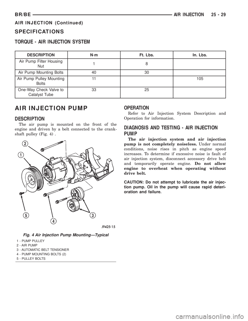
DESCRIPTION
The air pump is mounted on the front of the
engine and driven by a belt connected to the crank-
shaft pulley (Fig. 4) .
OPERATION
Refer to Air Injection System Description and
Operation for information.
DIAGNOSIS AND TESTING - AIR INJECTION
PUMP
The air injection system and air injection
pump is not completely noiseless.Under normal
conditions, noise rises in pitch as engine speed
increases. To determine if excessive noise is fault of
air injection system, disconnect accessory drive belt
and temporarily operate engine.Do not allow
engine to overheat when operating without
drive belt.
CAUTION: Do not attempt to lubricate the air injec-
tion pump. Oil in the pump will cause rapid deteri-
oration and failure.
Fig. 4 Air Injection Pump MountingÐTypical
1 - PUMP PULLEY
2 - AIR PUMP
3 - AUTOMATIC BELT TENSIONER
4 - PUMP MOUNTING BOLTS (2)
5 - PULLEY BOLTS
BR/BEAIR INJECTION 25 - 29
AIR INJECTION (Continued)