2002 DODGE RAM engine overheat
[x] Cancel search: engine overheatPage 1273 of 2255
INSPECTION
Look at the stainless steel body of the converter,
inspect for bulging or other distortion that could be a
result of overheating. If the converter has a heat
shield attached make sure it is not bent or loose.
If you suspect internal damage to the catalyst, tap-
ping the bottom of the catalyst with a rubber mallet
may indicate a damaged core.
INSTALLATION
(1) Assemble converter and clamps loosely in
place.
(2) Install the exhaust pipe onto exhaust mani-
folds, tighten 31 N´m (23 ft. lbs.).
(3) Tighten all clamp nuts to 48 N´m (35 ft. lbs.)
torque.
(4) Lower the vehicle.
(5) Start the engine and inspect for exhaust leaks
and exhaust system contact with the body panels. A
minimum of 25.4 mm (1.0 in.) is required between
exhaust system components and body/frame parts.
Adjust the alignment, if needed.
CATALYTIC CONVERTER - 5.9L
HD/8.0L
DESCRIPTION
The stainless steel catalytic converter is located
under the vehicle, attached to the exhaust pipe(s).
OPERATION
The catalytic converter captures and burns any
unburned fuel mixture exiting the combustion cham-
bers during the exhaust stroke of the engine. This
process aids in reducing emissions output.
REMOVAL
(1) Raise and support vehicle.
(2) Saturate the bolts and nuts with heat valve
lubricant. Allow 5 minutes for penetration.
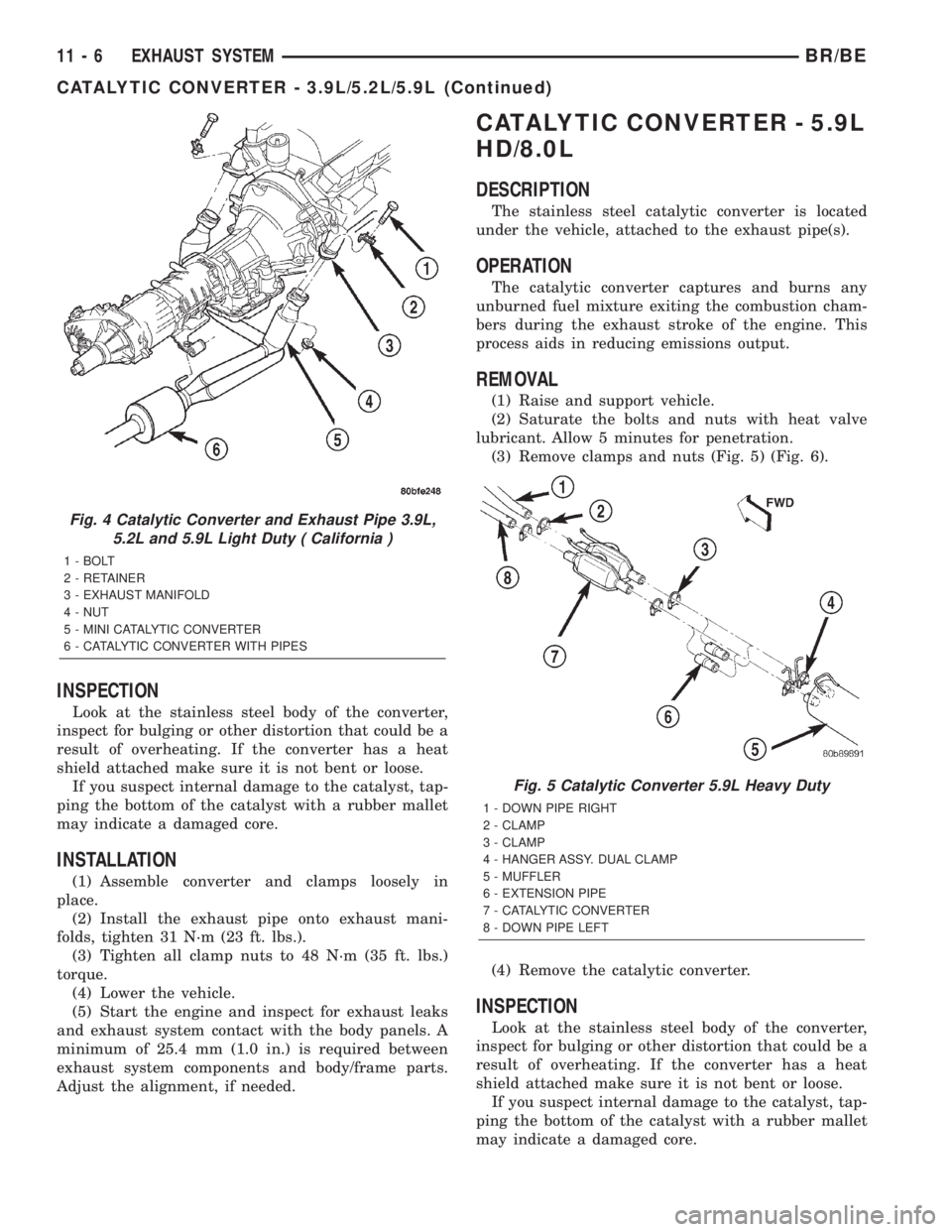
(3) Remove clamps and nuts (Fig. 5) (Fig. 6).
(4) Remove the catalytic converter.
INSPECTION
Look at the stainless steel body of the converter,
inspect for bulging or other distortion that could be a
result of overheating. If the converter has a heat
shield attached make sure it is not bent or loose.
If you suspect internal damage to the catalyst, tap-
ping the bottom of the catalyst with a rubber mallet
may indicate a damaged core.
Fig. 4 Catalytic Converter and Exhaust Pipe 3.9L,
5.2L and 5.9L Light Duty ( California )
1 - BOLT
2 - RETAINER
3 - EXHAUST MANIFOLD
4 - NUT
5 - MINI CATALYTIC CONVERTER
6 - CATALYTIC CONVERTER WITH PIPES
Fig. 5 Catalytic Converter 5.9L Heavy Duty
1 - DOWN PIPE RIGHT
2 - CLAMP
3 - CLAMP
4 - HANGER ASSY. DUAL CLAMP
5 - MUFFLER
6 - EXTENSION PIPE
7 - CATALYTIC CONVERTER
8 - DOWN PIPE LEFT
11 - 6 EXHAUST SYSTEMBR/BE
CATALYTIC CONVERTER - 3.9L/5.2L/5.9L (Continued)
Page 1282 of 2255
The turbocharger is lubricated by engine oil that is
pressurized, cooled, and filtered. The oil is delivered
to the turbocharger by a supply line that is tapped
into the oil filter head. The oil travels into the bear-
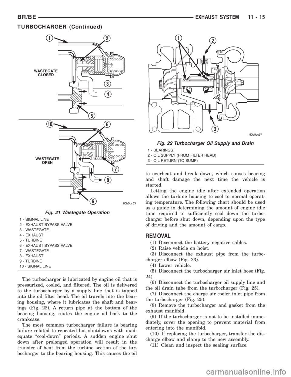
ing housing, where it lubricates the shaft and bear-
ings (Fig. 22). A return pipe at the bottom of the
bearing housing, routes the engine oil back to the
crankcase.
The most common turbocharger failure is bearing
failure related to repeated hot shutdowns with inad-
equate ªcool-downº periods. A sudden engine shut
down after prolonged operation will result in the
transfer of heat from the turbine section of the tur-
bocharger to the bearing housing. This causes the oilto overheat and break down, which causes bearing
and shaft damage the next time the vehicle is
started.
Letting the engine idle after extended operation
allows the turbine housing to cool to normal operat-
ing temperature. The following chart should be used
as a guide in determining the amount of engine idle
time required to sufficiently cool down the turbo-
charger before shut down, depending upon the type
of driving and the amount of cargo.
REMOVAL
(1) Disconnect the battery negative cables.
(2) Raise vehicle on hoist.
(3) Disconnect the exhaust pipe from the turbo-
charger elbow (Fig. 23).
(4) Lower vehicle.
(5) Disconnect the turbocharger air inlet hose (Fig.
24).
(6) Disconnect the turbocharger oil supply line and
the oil drain tube from the turbocharger (Fig. 25).
(7) Disconnect the charge air cooler inlet pipe from
the turbocharger (Fig. 25).
(8) Remove the turbocharger and gasket from the
exhaust manifold.
(9) If the turbocharger is not to be installed imme-
diately, cover the opening to prevent material from
entering into the manifold.
(10) If replacing the turbocharger, transfer the dis-
charge elbow and clamp to the new assembly.
(11) Clean and inspect the sealing surface.
Fig. 21 Wastegate Operation
1 - SIGNAL LINE
2 - EXHAUST BYPASS VALVE
3 - WASTEGATE
4 - EXHAUST
5 - TURBINE
6 - EXHAUST BYPASS VALVE
7 - WASTEGATE
8 - EXHAUST
9 - TURBINE
10 - SIGNAL LINE
Fig. 22 Turbocharger Oil Supply and Drain
1 - BEARINGS
2 - OIL SUPPLY (FROM FILTER HEAD)
3 - OIL RETURN (TO SUMP)
BR/BEEXHAUST SYSTEM 11 - 15
TURBOCHARGER (Continued)
Page 1399 of 2255
(2) Note RPM drop for each cylinder. As an alter-
native, loosen high-pressure fuel line fitting at fuel
injector connector tube (Fig. 15). Listen for a change
in engine speed. After testing, tighten line fitting to
40 N´m (30 ft. lbs.) torque. If engine speed drops,
injector was operating normally. If engine speed
remains same, injector may be malfunctioning. Test
all injectors in same manner one at a time.(3) Once injector has been found to be malfunc-
tioning, remove it from engine and test it. Refer to
Fuel Injector Removal/Installation.
WARNING: FUEL INJECTOR TESTERS CAN
DEVELOP EXTREMELY HIGH PRESSURES. FUEL
UNDER THIS AMOUNT OF PRESSURE CAN PENE-
TRATE SKIN AND CAUSE PERSONAL INJURY.
WEAR SAFETY GOGGLES AND ADEQUATE PRO-
TECTIVE CLOTHING. AVOID CONTACT WITH FUEL
SPRAY WHEN OPERATING INJECTOR TESTOR.
(4)
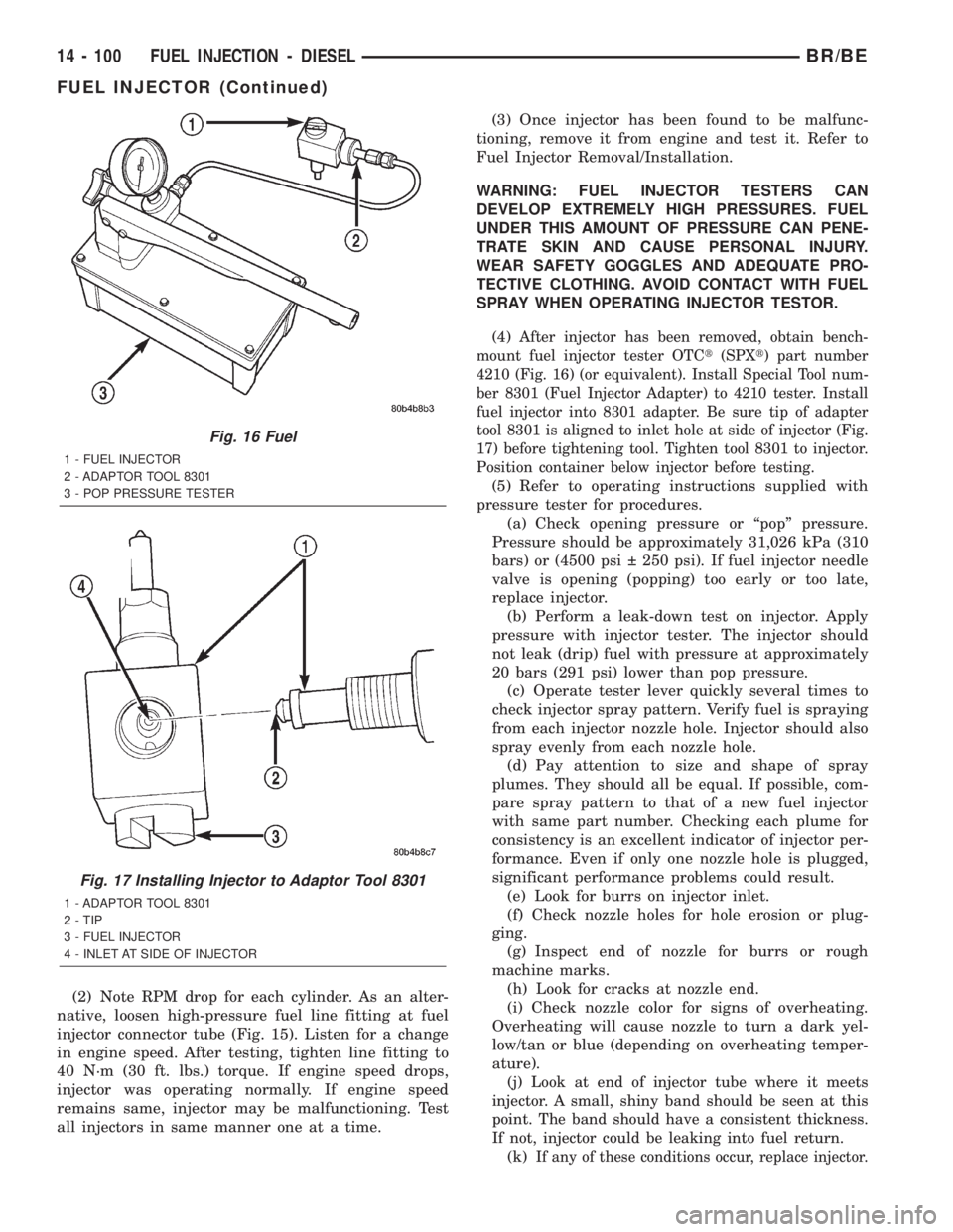
After injector has been removed, obtain bench-
mount fuel injector tester OTCt(SPXt) part number
4210 (Fig. 16) (or equivalent). Install Special Tool num-
ber 8301 (Fuel Injector Adapter) to 4210 tester. Install
fuel injector into 8301 adapter. Be sure tip of adapter
tool 8301 is aligned to inlet hole at side of injector (Fig.
17) before tightening tool. Tighten tool 8301 to injector.
Position container below injector before testing.
(5) Refer to operating instructions supplied with
pressure tester for procedures.
(a) Check opening pressure or ªpopº pressure.
Pressure should be approximately 31,026 kPa (310
bars) or (4500 psi 250 psi). If fuel injector needle
valve is opening (popping) too early or too late,
replace injector.
(b) Perform a leak-down test on injector. Apply
pressure with injector tester. The injector should
not leak (drip) fuel with pressure at approximately
20 bars (291 psi) lower than pop pressure.
(c) Operate tester lever quickly several times to
check injector spray pattern. Verify fuel is spraying
from each injector nozzle hole. Injector should also
spray evenly from each nozzle hole.
(d) Pay attention to size and shape of spray
plumes. They should all be equal. If possible, com-
pare spray pattern to that of a new fuel injector
with same part number. Checking each plume for
consistency is an excellent indicator of injector per-
formance. Even if only one nozzle hole is plugged,
significant performance problems could result.
(e) Look for burrs on injector inlet.
(f) Check nozzle holes for hole erosion or plug-
ging.
(g) Inspect end of nozzle for burrs or rough
machine marks.
(h) Look for cracks at nozzle end.
(i) Check nozzle color for signs of overheating.
Overheating will cause nozzle to turn a dark yel-
low/tan or blue (depending on overheating temper-
ature).
(j)
Look at end of injector tube where it meets
injector. A small, shiny band should be seen at this
point. The band should have a consistent thickness.
If not, injector could be leaking into fuel return.
(k)If any of these conditions occur, replace injector.
Fig. 16 Fuel
1 - FUEL INJECTOR
2 - ADAPTOR TOOL 8301
3 - POP PRESSURE TESTER
Fig. 17 Installing Injector to Adaptor Tool 8301
1 - ADAPTOR TOOL 8301
2 - TIP
3 - FUEL INJECTOR
4 - INLET AT SIDE OF INJECTOR
14 - 100 FUEL INJECTION - DIESELBR/BE
FUEL INJECTOR (Continued)
Page 1457 of 2255
HARD SHIFTING
Hard shifting is usually caused by a low lubricant
level, improper or contaminated lubricants. The con-
sequence of using non-recommended lubricants is
noise, excessive wear, internal bind and hard shift-
ing. Substantial lubricant leaks can result in gear,
shift rail, synchro, and bearing damage. If a leak
goes undetected for an extended period, the first indi-
cations of component damage are usually hard shift-
ing and noise.
Component damage, incorrect clutch adjustment or
damaged clutch pressure plate or disc are additional
probable causes of increased shift effort. Incorrect
adjustment or a worn/damaged pressure plate or disc
can cause incorrect release. If clutch problem is
advanced, gear clash during shifts can result. Worn
or damaged synchro rings can cause gear clash when
shifting into any forward gear. In some new or
rebuilt transmissions, new synchro rings may tend to
stick slightly causing hard or noisy shifts. In most
cases this condition will decline as the rings wear-in.
TRANSMISSION NOISE
Most manual transmissions make some noise dur-
ing normal operation. Rotating gears generate a mild
whine that is audible, but generally only at extreme
speeds. Severe highly audible transmission noise is
generally the initial indicator of a lubricant problem.
Insufficient, improper or contaminated lubricant
will promote rapid wear of gears, synchros, shift
rails, forks and bearings. The overheating caused by
a lubricant problem, can also lead to gear breakage.
REMOVAL
(1) Disconnect battery negative cable.
(2) Shift transmission into Neutral.
(3) Remove shift boot screws from floorpan and
slide boot upward on the shift lever.
(4) Remove shift lever extension from shift tower
and lever assembly.
(5) Remove shift tower bolts holding tower to iso-
lator plate and transmission shift cover.
(6) Remove shift tower and isolator plate from
transmission shift cover.
(7) Raise and support vehicle.
(8) Remove skid plate, if equipped.
(9) Mark propeller shaft and axle yokes for instal-
lation reference and remove shaft/shafts.
(10) Remove exhaust system Y-pipe.
(11) Disconnect speed sensor and backup light
switch connectors.
(12) Support engine with safety stand and a wood
block.
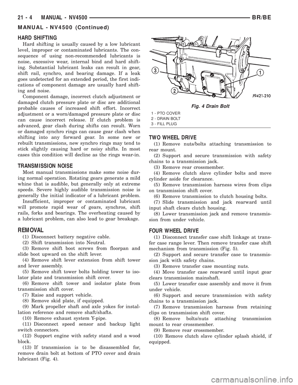
(13) If transmission is to be disassembled for,
remove drain bolt at bottom of PTO cover and drain
lubricant (Fig. 4).
TWO WHEEL DRIVE
(1) Remove nuts/bolts attaching transmission to
rear mount.
(2) Support and secure transmission with safety
chains to a transmission jack.
(3) Remove rear crossmember.
(4) Remove clutch slave cylinder bolts and move
cylinder aside for clearance.
(5) Remove transmission harness wires from clips
on transmission shift cover.
(6) Remove transmission to clutch housing bolts.
(7) Slide transmission and jack rearward until
input shaft clears clutch housing.
(8) Lower transmission jack and remove transmis-
sion from under vehicle.
FOUR WHEEL DRIVE
(1) Disconnect transfer case shift linkage at trans-
fer case range lever. Then remove transfer case shift
mechanism from transmission (Fig. 5).
(2) Support and secure transfer case to transmis-
sion jack with safety chains.
(3) Remove transfer case mounting nuts.
(4) Move transfer case rearward until input gear
clears transmission mainshaft.
(5) Lower transfer case assembly and move it from
under vehicle.
(6) Support and secure transmission with safety
chains to a transmission jack.
(7) Remove transmission harness from retaining
clips on transmission shift cover.
(8) Remove bolts/nuts attaching transmission
mount to rear crossmember.
(9) Remove rear crossmember.
(10) Remove clutch slave cylinder splash shield, if
equipped.
Fig. 4 Drain Bolt
1 - PTO COVER
2 - DRAIN BOLT
3 - FILL PLUG
21 - 4 MANUAL - NV4500BR/BE
MANUAL - NV4500 (Continued)
Page 1502 of 2255
TRANSMISSION NOISE
Most manual transmissions make some noise dur-
ing normal operation. Rotating gears generate a mild
whine that is audible, but generally only at extreme
speeds. Severe highly audible transmission noise is
generally the initial indicator of a lubricant problem.
Insufficient, improper or contaminated lubricant
will promote rapid wear of gears, synchros, shift
rails, forks and bearings. The overheating caused by
a lubricant problem, can also lead to gear breakage.
REMOVAL
NOTE: Use a heavy duty scissors style transmis-
sion jack for remove of the transmission.
(1) Disconnect battery negative cable.
(2) Shift transmission into Neutral.
(3) Remove screws attaching shift boot to floorpan.
Then slide boot upward on the shift lever.
(4) Remove the bolts holding the shift tower to the
isolator plate and transmission gear case.
(5) Remove the shift tower and isolator plate from
the transmission gear case.
(6) Raise and support vehicle.
(7) Remove skid plate, if equipped.
(8) Mark propeller shaft/shafts and axle yokes for
installation reference.
(9) Remove propeller shaft.
(10) Disconnect and remove exhaust system as
necessary.
(11) Disconnect wires at backup light switch.
(12) Support engine with adjustable safety stand
and wood block.
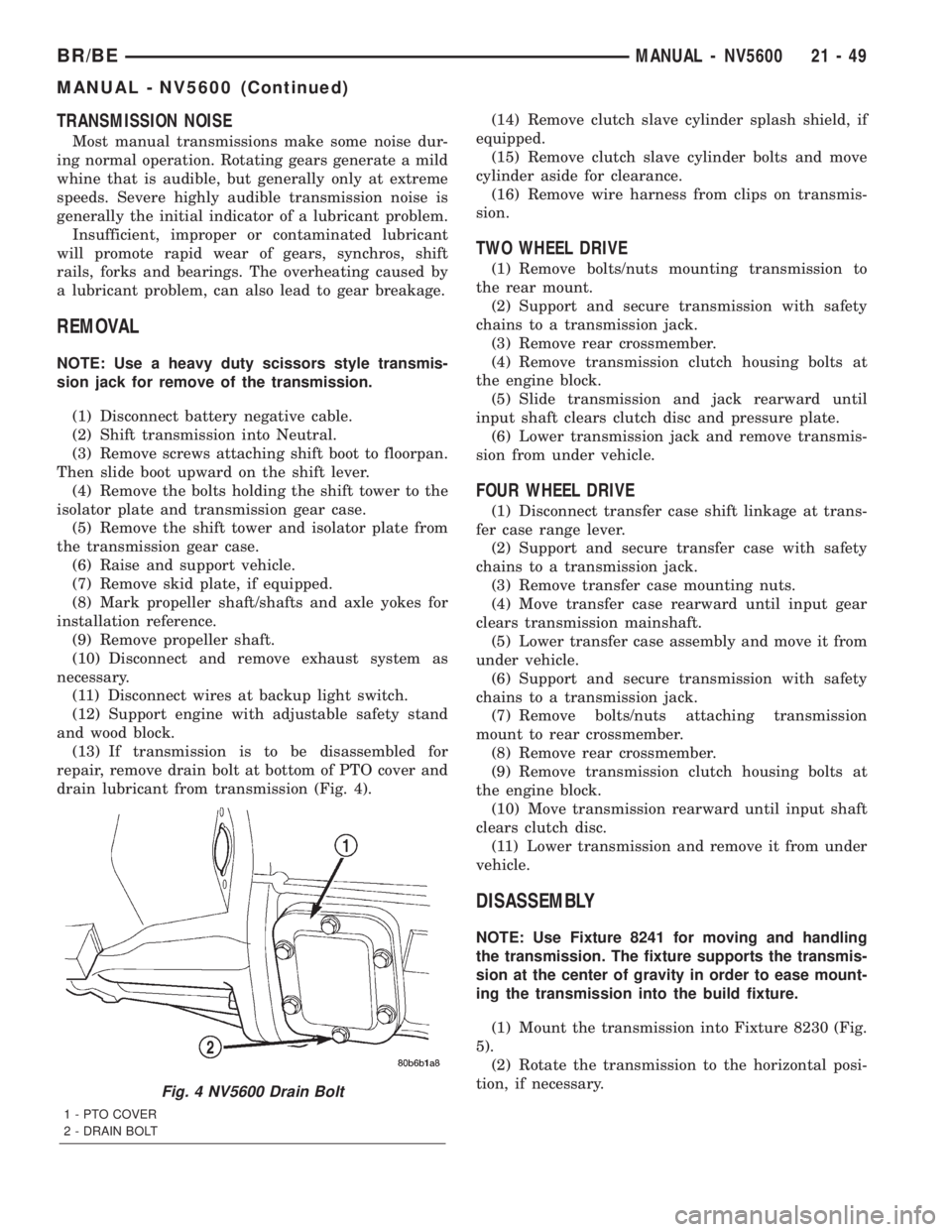
(13) If transmission is to be disassembled for
repair, remove drain bolt at bottom of PTO cover and
drain lubricant from transmission (Fig. 4).(14) Remove clutch slave cylinder splash shield, if
equipped.
(15) Remove clutch slave cylinder bolts and move
cylinder aside for clearance.
(16) Remove wire harness from clips on transmis-
sion.
TWO WHEEL DRIVE
(1) Remove bolts/nuts mounting transmission to
the rear mount.
(2) Support and secure transmission with safety
chains to a transmission jack.
(3) Remove rear crossmember.
(4) Remove transmission clutch housing bolts at
the engine block.
(5) Slide transmission and jack rearward until
input shaft clears clutch disc and pressure plate.
(6) Lower transmission jack and remove transmis-
sion from under vehicle.
FOUR WHEEL DRIVE
(1) Disconnect transfer case shift linkage at trans-
fer case range lever.
(2) Support and secure transfer case with safety
chains to a transmission jack.
(3) Remove transfer case mounting nuts.
(4) Move transfer case rearward until input gear
clears transmission mainshaft.
(5) Lower transfer case assembly and move it from
under vehicle.
(6) Support and secure transmission with safety
chains to a transmission jack.
(7) Remove bolts/nuts attaching transmission
mount to rear crossmember.
(8) Remove rear crossmember.
(9) Remove transmission clutch housing bolts at
the engine block.
(10) Move transmission rearward until input shaft
clears clutch disc.
(11) Lower transmission and remove it from under
vehicle.
DISASSEMBLY
NOTE: Use Fixture 8241 for moving and handling
the transmission. The fixture supports the transmis-
sion at the center of gravity in order to ease mount-
ing the transmission into the build fixture.
(1) Mount the transmission into Fixture 8230 (Fig.
5).
(2) Rotate the transmission to the horizontal posi-
tion, if necessary.
Fig. 4 NV5600 Drain Bolt
1 - PTO COVER
2 - DRAIN BOLT
BR/BEMANUAL - NV5600 21 - 49
MANUAL - NV5600 (Continued)
Page 1610 of 2255

FLUID AND FILTER
DIAGNOSIS AND TESTING
DIAGNOSIS AND TESTING - EFFECTS OF
INCORRECT FLUID LEVEL
A low fluid level allows the pump to take in air
along with the fluid. Air in the fluid will cause fluid
pressures to be low and develop slower than normal.
If the transmission is overfilled, the gears churn the
fluid into foam. This aerates the fluid and causing
the same conditions occurring with a low level. In
either case, air bubbles cause fluid overheating, oxi-
dation and varnish buildup which interferes with
valve and clutch operation. Foaming also causes fluid
expansion which can result in fluid overflow from the
transmission vent or fill tube. Fluid overflow can eas-
ily be mistaken for a leak if inspection is not careful.
DIAGNOSIS AND TESTING - CAUSES OF
BURNT FLUID
Burnt, discolored fluid is a result of overheating
which has two primary causes.
(1) A result of restricted fluid flow through the
main and/or auxiliary cooler. This condition is usu-
ally the result of a faulty or improperly installed
drainback valve, a damaged main cooler, or severe
restrictions in the coolers and lines caused by debris
or kinked lines.
(2) Heavy duty operation with a vehicle not prop-
erly equipped for this type of operation. Trailer tow-
ing or similar high load operation will overheat the
transmission fluid if the vehicle is improperly
equipped. Such vehicles should have an auxiliary
transmission fluid cooler, a heavy duty cooling sys-
tem, and the engine/axle ratio combination needed to
handle heavy loads.
DIAGNOSIS AND TESTING - FLUID
CONTAMINATION
Transmission fluid contamination is generally a
result of:
²adding incorrect fluid
²failure to clean dipstick and fill tube when
checking level
²engine coolant entering the fluid
²internal failure that generates debris
²overheat that generates sludge (fluid break-
down)
²failure to reverse flush cooler and lines after
repair
²failure to replace contaminated converter after
repair
The use of non-recommended fluids can result in
transmission failure. The usual results are erratic
shifts, slippage, abnormal wear and eventual failure
due to fluid breakdown and sludge formation. Avoid
this condition by using recommended fluids only.
The dipstick cap and fill tube should be wiped
clean before checking fluid level. Dirt, grease and
other foreign material on the cap and tube could fall
into the tube if not removed beforehand. Take the
time to wipe the cap and tube clean before withdraw-
ing the dipstick.
Engine coolant in the transmission fluid is gener-
ally caused by a cooler malfunction. The only remedy
is to replace the radiator as the cooler in the radiator
is not a serviceable part. If coolant has circulated
through the transmission, an overhaul is necessary.
The transmission cooler and lines should be
reverse flushed whenever a malfunction generates
sludge and/or debris. The torque converter should
also be replaced at the same time.
Failure to flush the cooler and lines will result in
recontamination. Flushing applies to auxiliary coolers
as well. The torque converter should also be replaced
whenever a failure generates sludge and debris. This is
necessary because normal converter flushing procedures
will not remove all contaminants.
STANDARD PROCEDURE
STANDARD PROCEDURE - FLUID LEVEL
CHECK
Low fluid level can cause a variety of conditions
because it allows the pump to take in air along with
the fluid. As in any hydraulic system, air bubbles
make the fluid spongy, therefore, pressures will be
low and build up slowly.
Improper filling can also raise the fluid level too
high. When the transmssion has too much fluid, the
geartrain churns up foam and cause the same condi-
tions which occur with a low fluid level.
Fig. 88 Installing Overdrive Housing Seal
1 - SPECIAL TOOL C-3995-A OR C-3972-A
2 - SPECIAL TOOL C-4471
BR/BEAUTOMATIC TRANSMISSION - 46RE 21 - 157
EXTENSION HOUSING SEAL (Continued)
Page 1611 of 2255
In either case, air bubbles can cause overheating
and/or fluid oxidation, and varnishing. This can
interfere with normal valve, clutch, and accumulator
operation. Foaming can also result in fluid escaping
from the transmission vent where it may be mis-
taken for a leak.
Along with fluid level, it is important to check the
condition of the fluid. When the fluid smells burned,
and is contaminated with metal or friction material
particles, a complete transmission recondition is
needed. Be sure to examine the fluid on the dipstick
closely. If there is any doubt about its condition,
drain out a sample for a double check.
After the fluid has been checked, seat the dipstick
fully to seal out water and dirt.
The transmission has a dipstick to check oil level.
It is located on the right side of the engine. Be sure
to wipe all dirt from dipstick handle before removing.
Fluid level is checked with the engine running at
curb idle speed, the transmission in NEUTRAL and
the transmission fluid at normal operating tempera-
ture.The engine should be running at idle
speed for at least one minute, with the vehicle
on level ground.
The transmission fluid level can be checked two
ways.
PROCEDURE ONE
(1) Transmission fluid must be at normal operat-
ing temperature for accurate fluid level check. Drive
vehicle if necessary to bring fluid temperature up to
normal hot operating temperature of 82ÉC (180ÉF).
(2) Position vehicle on level surface.
(3) Start and run engine at curb idle speed.
(4) Apply parking brakes.
(5) Shift transmission momentarily into all gear
ranges. Then shift transmission back to NEUTRAL.
(6) Clean top of filler tube and dipstick to keep
dirt from entering tube.
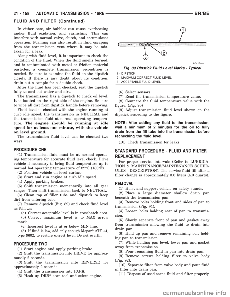
(7) Remove dipstick (Fig. 89) and check fluid level
as follows:
(a) Correct acceptable level is in crosshatch area.
(b) Correct maximum level is to MAX arrow
mark.
(c) Incorrect level is at or below MIN line.
(d)
If fluid is low, add only enough MopartATF +4,
type 9602, to restore correct level. Do not overfill.
PROCEDURE TWO
(1) Start engine and apply parking brake.
(2) Shift the transmission into DRIVE for approxi-
mately 2 seconds.
(3) Shift the transmission into REVERSE for
approximately 2 seconds.
(4) Shift the transmission into PARK.
(5) Hook up DRBtscan tool and select engine.(6) Select sensors.
(7) Read the transmission temperature value.
(8) Compare the fluid temperature value with the
figure. (Fig. 90)
(9) Adjust transmission fluid level shown on the
dipstick according to the figure.
NOTE: After adding any fluid to the transmission,
wait a minimum of 2 minutes for the oil to fully
drain from the fill tube into the transmission before
rechecking the fluid level.
(10) Check transmission for leaks.
STANDARD PROCEDURE - FLUID AND FILTER
REPLACEMENT
For proper service intervals (Refer to LUBRICA-
TION & MAINTENANCE/MAINTENANCE SCHED-
ULES - DESCRIPTION). The service fluid fill after a
filter change is approximately 3.8 liters (4.0 quarts).
REMOVAL
(1) Hoist and support vehicle on safety stands.
(2) Place a large diameter shallow drain pan
beneath the transmission pan.
(3) Remove bolts holding front and sides of pan to
transmission (Fig. 91).
(4) Loosen bolts holding rear of pan to transmis-
sion.
(5) Slowly separate front of pan and gasket away
from transmission allowing the fluid to drain into
drain pan.
(6) Hold up pan and remove remaining bolt hold-
ing pan to transmission.
(7) While holding pan level, lower pan and gasket
away from transmission.
(8) Pour remaining fluid in pan into drain pan.
(9) Remove screws holding filter to valve body
(Fig. 92).
(10) Separate filter from valve body and pour fluid
in filter into drain pan.
(11) Dispose of used trans fluid and filter properly.
Fig. 89 Dipstick Fluid Level Marks - Typical
1 - DIPSTICK
2 - MAXIMUM CORRECT FLUID LEVEL
3 - ACCEPTABLE FLUID LEVEL
21 - 158 AUTOMATIC TRANSMISSION - 46REBR/BE
FLUID AND FILTER (Continued)
Page 1780 of 2255
INSTALLATION
(1) Place seal in position on overdrive housing.
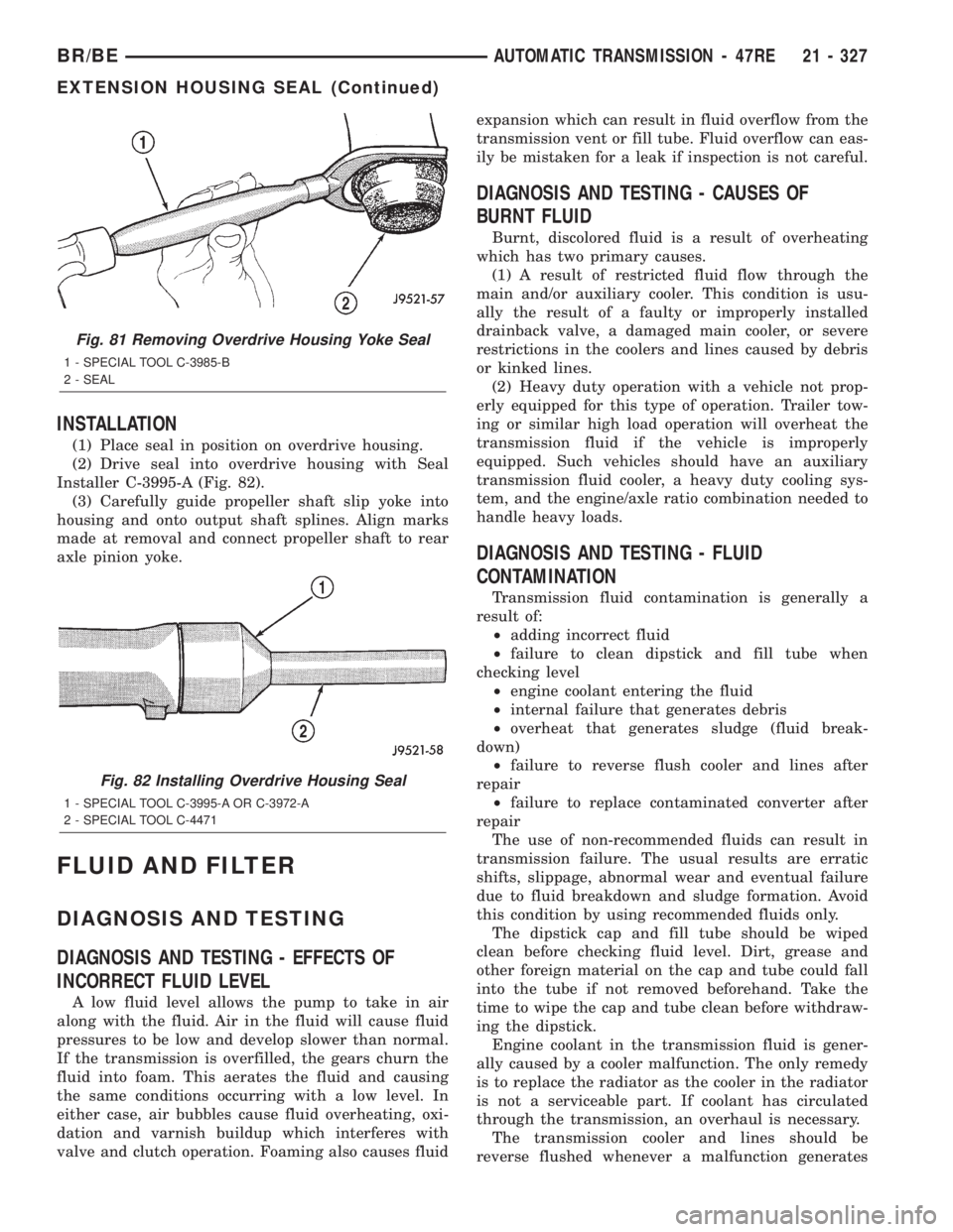
(2) Drive seal into overdrive housing with Seal
Installer C-3995-A (Fig. 82).
(3) Carefully guide propeller shaft slip yoke into
housing and onto output shaft splines. Align marks
made at removal and connect propeller shaft to rear
axle pinion yoke.
FLUID AND FILTER
DIAGNOSIS AND TESTING
DIAGNOSIS AND TESTING - EFFECTS OF
INCORRECT FLUID LEVEL
A low fluid level allows the pump to take in air
along with the fluid. Air in the fluid will cause fluid
pressures to be low and develop slower than normal.
If the transmission is overfilled, the gears churn the
fluid into foam. This aerates the fluid and causing
the same conditions occurring with a low level. In
either case, air bubbles cause fluid overheating, oxi-
dation and varnish buildup which interferes with
valve and clutch operation. Foaming also causes fluidexpansion which can result in fluid overflow from the
transmission vent or fill tube. Fluid overflow can eas-
ily be mistaken for a leak if inspection is not careful.
DIAGNOSIS AND TESTING - CAUSES OF
BURNT FLUID
Burnt, discolored fluid is a result of overheating
which has two primary causes.
(1) A result of restricted fluid flow through the
main and/or auxiliary cooler. This condition is usu-
ally the result of a faulty or improperly installed
drainback valve, a damaged main cooler, or severe
restrictions in the coolers and lines caused by debris
or kinked lines.
(2) Heavy duty operation with a vehicle not prop-
erly equipped for this type of operation. Trailer tow-
ing or similar high load operation will overheat the
transmission fluid if the vehicle is improperly
equipped. Such vehicles should have an auxiliary
transmission fluid cooler, a heavy duty cooling sys-
tem, and the engine/axle ratio combination needed to
handle heavy loads.
DIAGNOSIS AND TESTING - FLUID
CONTAMINATION
Transmission fluid contamination is generally a
result of:
²adding incorrect fluid
²failure to clean dipstick and fill tube when
checking level
²engine coolant entering the fluid
²internal failure that generates debris
²overheat that generates sludge (fluid break-
down)
²failure to reverse flush cooler and lines after
repair
²failure to replace contaminated converter after
repair
The use of non-recommended fluids can result in
transmission failure. The usual results are erratic
shifts, slippage, abnormal wear and eventual failure
due to fluid breakdown and sludge formation. Avoid
this condition by using recommended fluids only.
The dipstick cap and fill tube should be wiped
clean before checking fluid level. Dirt, grease and
other foreign material on the cap and tube could fall
into the tube if not removed beforehand. Take the
time to wipe the cap and tube clean before withdraw-
ing the dipstick.
Engine coolant in the transmission fluid is gener-
ally caused by a cooler malfunction. The only remedy
is to replace the radiator as the cooler in the radiator
is not a serviceable part. If coolant has circulated
through the transmission, an overhaul is necessary.
The transmission cooler and lines should be
reverse flushed whenever a malfunction generates
Fig. 81 Removing Overdrive Housing Yoke Seal
1 - SPECIAL TOOL C-3985-B
2 - SEAL
Fig. 82 Installing Overdrive Housing Seal
1 - SPECIAL TOOL C-3995-A OR C-3972-A
2 - SPECIAL TOOL C-4471
BR/BEAUTOMATIC TRANSMISSION - 47RE 21 - 327
EXTENSION HOUSING SEAL (Continued)