2002 DODGE RAM cooling
[x] Cancel search: coolingPage 1446 of 2255
INSTALLATION
INSTALLATION - GASOLINE ENGINE
(1) Install the front pump bracket and tighten
bolts to 47 N´m (35 ft. lbs.). On 8.0L engine install
rear pump bracket and tighten nut to 47 N´m (35 ft.
lbs.), tighten bolts to 24 N´m (18 ft. lbs.).
(2) Install the pump pulley with Installer
C-4063±B, (Refer to 19 - STEERING/PUMP/PULLEY
- INSTALLATION).
(3) Install steering pump assembly on the engine
block. Install the upper stud and bolt in bracket.
(4) Pivot the pump down past the coolant tube and
install the lower bolts in bracket.
(5) Tighten the bolts and nut to 41 N´m (30 ft.
lbs.).
(6) Connect the hoses to the pump.
(7) Install the serpentine drive belt, (Refer to 7 -
COOLING/ACCESSORY DRIVE/DRIVE BELTS -
INSTALLATION), (Refer to 7 - COOLING/ACCES-
SORY DRIVE/DRIVE BELTS - INSTALLATION).
(8) Fill the reservoir with power steering fluid,
(Refer to 19 - STEERING/PUMP - STANDARD PRO-
CEDURE).
INSTALLATION - DIESEL ENGINE
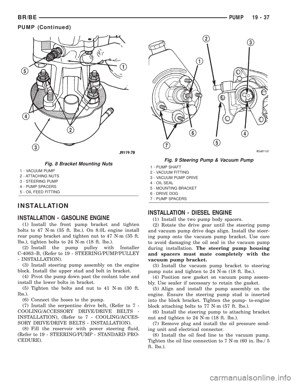
(1) Install the two pump body spacers.
(2) Rotate the drive gear until the steering pump
and vacuum pump drive dogs align. Install the steer-
ing pump onto the vacuum pump bracket. Use care
to avoid damaging the oil seal in the vacuum pump
during installation.The steering pump housing
and spacers must mate completely with the
vacuum pump bracket.
(3) Install the vacuum pump bracket to steering
pump nuts and tighten to 24 N´m (18 ft. lbs.).
(4) Position new gasket on vacuum pump assem-
bly. Use sealer if necessary to retain the gasket.
(5) Align and install the pump assembly on the
engine. Ensure the steering pump stud is inserted
into the block bracket. Tighten the pump- to-engine
block attaching bolts to 77 N´m (57 ft. lbs.).
(6) Install the steering pump to attaching bracket
nut and tighten to 24 N´m (18 ft. lbs.).
(7) Remove plug and install the oil pressure send-
ing unit and electrical connector.
(8) Install the oil feed line to the vacuum pump.
Tighten the oil line connection to 7 N´m (60 in. lbs./ 5
ft. lbs.).
Fig. 8 Bracket Mounting Nuts
1 - VACUUM PUMP
2 - ATTACHING NUTS
3 - STEERING PUMP
4 - PUMP SPACERS
5 - OIL FEED FITTING
Fig. 9 Steering Pump & Vacuum Pump
1 - PUMP SHAFT
2 - VACUUM FITTING
3 - VACUUM PUMP DRIVE
4 - OIL SEAL
5 - MOUNTING BRACKET
6 - DRIVE DOG
7 - PUMP SPACERS
BR/BEPUMP 19 - 37
PUMP (Continued)
Page 1447 of 2255
(9) Install the fluid hoses to the power steering
pump. Tighten the pressure fitting at the pump to 31
N´m (23 ft. lbs.).
(10) Install and clamp the hose on the vacuum
pump.
(11) Install the serpentine belt, (Refer to 7 -
COOLING/ACCESSORY DRIVE/DRIVE BELTS -
INSTALLATION).
(12) Fill the reservoir with power steering fluid,
(Refer to 19 - STEERING/PUMP - STANDARD PRO-
CEDURE).
(13) Start the engine and check the operation of
the brakes.
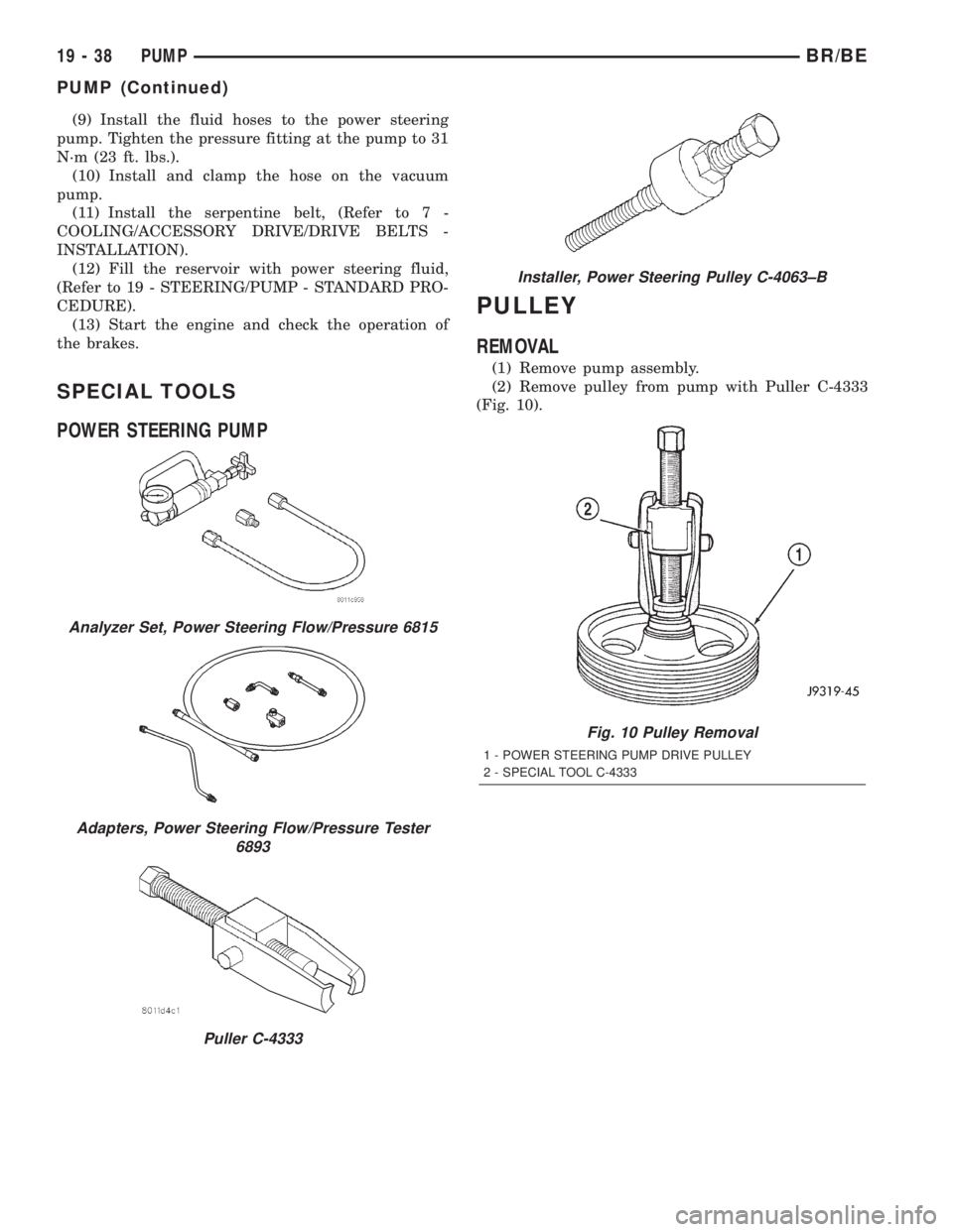
SPECIAL TOOLS
POWER STEERING PUMP
PULLEY
REMOVAL
(1) Remove pump assembly.
(2) Remove pulley from pump with Puller C-4333
(Fig. 10).
Analyzer Set, Power Steering Flow/Pressure 6815
Adapters, Power Steering Flow/Pressure Tester
6893
Puller C-4333
Installer, Power Steering Pulley C-4063±B
Fig. 10 Pulley Removal
1 - POWER STEERING PUMP DRIVE PULLEY
2 - SPECIAL TOOL C-4333
19 - 38 PUMPBR/BE
PUMP (Continued)
Page 1560 of 2255
CONDITION POSSIBLE CAUSES CORRECTION
BUZZING NOISE 1. Fluid Level Low 1. Add fluid and check for leaks.
2. Shift Cable Mis-assembled. 2. Route cable away from engine and bell
housing.
3. Valve Body Mis-assembled. 3. Remove, disassemble, inspect valve
body. Reassemble correctly if necessary.
Replace assembly if valves or springs are
damaged. Check for loose bolts or screws.
4. Pump Passages Leaking. 4. Check pump for porous casting, scores
on mating surfaces and excess rotor
clearance. Repair as required. Loose pump
bolts.
5. Cooling System Cooler Plugged. 5. Flow check cooler circuit. Repair as
needed.
6. Overrunning Clutch Damaged. 6. Replace clutch.
SLIPS IN REVERSE ONLY 1. Fluid Level Low. 1. Add fluid and check for leaks.
2. Gearshift Linkage Mis-adjusted. 2. Adjust linkage.
3. Rear Band Mis-adjusted. 3. Adjust band.
4. Rear Band Worn. 4. Replace as required.
5. Overdrive Direct Clutch Worn. 5. Disassemble overdrive. Repair as
needed.
6. Hydraulic Pressure Too Low. 6. Perform hydraulic pressure tests to
determine cause.
7. Rear Servo Leaking. 7. Air pressure check clutch-servo operation
and repair as required.
8. Band Linkage Binding. 8. Inspect and repair as required.
SLIPS IN FORWARD
DRIVE RANGES1. Fluid Level Low. 1. Add fluid and check for leaks.
2. Fluid Foaming. 2. Check for high oil level, bad pump
gasket or seals, dirt between pump halves
and loose pump bolts. Replace pump if
necessary.
3. Throttle Linkage Mis-adjusted. 3. Adjust linkage.
4. Gearshift Linkage Mis-adjusted. 4. Adjust linkage.
5. Rear Clutch Worn. 5. Inspect and replace as needed.
6. Low Hydraulic Pressure Due to
Worn Pump, Incorrect Control
Pressure Adjustments, Valve Body
Warpage or Malfunction, Sticking,
Leaking Seal Rings, Clutch Seals
Leaking, Servo Leaks, Clogged Filter
or Cooler Lines.6. Perform hydraulic and air pressure tests
to determine cause.
7. Rear Clutch Malfunction, Leaking
Seals or Worn Plates.7. Air pressure check clutch-servo operation
and repair as required.
8. Overrunning Clutch Worn, Not
Holding (Slips in 1 Only).8. Replace Clutch.
BR/BEAUTOMATIC TRANSMISSION - 46RE 21 - 107
AUTOMATIC TRANSMISSION - 46RE (Continued)
Page 1610 of 2255

FLUID AND FILTER
DIAGNOSIS AND TESTING
DIAGNOSIS AND TESTING - EFFECTS OF
INCORRECT FLUID LEVEL
A low fluid level allows the pump to take in air
along with the fluid. Air in the fluid will cause fluid
pressures to be low and develop slower than normal.
If the transmission is overfilled, the gears churn the
fluid into foam. This aerates the fluid and causing
the same conditions occurring with a low level. In
either case, air bubbles cause fluid overheating, oxi-
dation and varnish buildup which interferes with
valve and clutch operation. Foaming also causes fluid
expansion which can result in fluid overflow from the
transmission vent or fill tube. Fluid overflow can eas-
ily be mistaken for a leak if inspection is not careful.
DIAGNOSIS AND TESTING - CAUSES OF
BURNT FLUID
Burnt, discolored fluid is a result of overheating
which has two primary causes.
(1) A result of restricted fluid flow through the
main and/or auxiliary cooler. This condition is usu-
ally the result of a faulty or improperly installed
drainback valve, a damaged main cooler, or severe
restrictions in the coolers and lines caused by debris
or kinked lines.
(2) Heavy duty operation with a vehicle not prop-
erly equipped for this type of operation. Trailer tow-
ing or similar high load operation will overheat the
transmission fluid if the vehicle is improperly
equipped. Such vehicles should have an auxiliary
transmission fluid cooler, a heavy duty cooling sys-
tem, and the engine/axle ratio combination needed to
handle heavy loads.
DIAGNOSIS AND TESTING - FLUID
CONTAMINATION
Transmission fluid contamination is generally a
result of:
²adding incorrect fluid
²failure to clean dipstick and fill tube when
checking level
²engine coolant entering the fluid
²internal failure that generates debris
²overheat that generates sludge (fluid break-
down)
²failure to reverse flush cooler and lines after
repair
²failure to replace contaminated converter after
repair
The use of non-recommended fluids can result in
transmission failure. The usual results are erratic
shifts, slippage, abnormal wear and eventual failure
due to fluid breakdown and sludge formation. Avoid
this condition by using recommended fluids only.
The dipstick cap and fill tube should be wiped
clean before checking fluid level. Dirt, grease and
other foreign material on the cap and tube could fall
into the tube if not removed beforehand. Take the
time to wipe the cap and tube clean before withdraw-
ing the dipstick.
Engine coolant in the transmission fluid is gener-
ally caused by a cooler malfunction. The only remedy
is to replace the radiator as the cooler in the radiator
is not a serviceable part. If coolant has circulated
through the transmission, an overhaul is necessary.
The transmission cooler and lines should be
reverse flushed whenever a malfunction generates
sludge and/or debris. The torque converter should
also be replaced at the same time.
Failure to flush the cooler and lines will result in
recontamination. Flushing applies to auxiliary coolers
as well. The torque converter should also be replaced
whenever a failure generates sludge and debris. This is
necessary because normal converter flushing procedures
will not remove all contaminants.
STANDARD PROCEDURE
STANDARD PROCEDURE - FLUID LEVEL
CHECK
Low fluid level can cause a variety of conditions
because it allows the pump to take in air along with
the fluid. As in any hydraulic system, air bubbles
make the fluid spongy, therefore, pressures will be
low and build up slowly.
Improper filling can also raise the fluid level too
high. When the transmssion has too much fluid, the
geartrain churns up foam and cause the same condi-
tions which occur with a low fluid level.
Fig. 88 Installing Overdrive Housing Seal
1 - SPECIAL TOOL C-3995-A OR C-3972-A
2 - SPECIAL TOOL C-4471
BR/BEAUTOMATIC TRANSMISSION - 46RE 21 - 157
EXTENSION HOUSING SEAL (Continued)
Page 1732 of 2255
CONDITION POSSIBLE CAUSES CORRECTION
BUZZING NOISE 1. Fluid Level Low 1. Add fluid and check for leaks.
2. Shift Cable Mis-assembled. 2. Route cable away from engine and bell
housing.
3. Valve Body Mis-assembled. 3. Remove, disassemble, inspect valve
body. Reassemble correctly if necessary.
Replace assembly if valves or springs are
damaged. Check for loose bolts or screws.
4. Pump Passages Leaking. 4. Check pump for porous casting, scores
on mating surfaces and excess rotor
clearance. Repair as required. Loose pump
bolts.
5. Cooling System Cooler Plugged. 5. Flow check cooler circuit. Repair as
needed.
6. Overrunning Clutch Damaged. 6. Replace clutch.
SLIPS IN REVERSE ONLY 1. Fluid Level Low. 1. Add fluid and check for leaks.
2. Gearshift Linkage Mis-adjusted. 2. Adjust linkage.
3. Rear Band Mis-adjusted. 3. Adjust band.
4. Rear Band Worn. 4. Replace as required.
5. Overdrive Direct Clutch Worn. 5. Disassemble overdrive. Repair as
needed.
6. Hydraulic Pressure Too Low. 6. Perform hydraulic pressure tests to
determine cause.
7. Rear Servo Leaking. 7. Air pressure check clutch-servo operation
and repair as required.
8. Band Linkage Binding. 8. Inspect and repair as required.
SLIPS IN FORWARD
DRIVE RANGES1. Fluid Level Low. 1. Add fluid and check for leaks.
2. Fluid Foaming. 2. Check for high oil level, bad pump
gasket or seals, dirt between pump halves
and loose pump bolts. Replace pump if
necessary.
3. Throttle Linkage Mis-adjusted. 3. Adjust linkage.
4. Gearshift Linkage Mis-adjusted. 4. Adjust linkage.
5. Rear Clutch Worn. 5. Inspect and replace as needed.
6. Low Hydraulic Pressure Due to
Worn Pump, Incorrect Control
Pressure Adjustments, Valve Body
Warpage or Malfunction, Sticking,
Leaking Seal Rings, Clutch Seals
Leaking, Servo Leaks, Clogged Filter
or Cooler Lines.6. Perform hydraulic and air pressure tests
to determine cause.
7. Rear Clutch Malfunction, Leaking
Seals or Worn Plates.7. Air pressure check clutch-servo operation
and repair as required.
8. Overrunning Clutch Worn, Not
Holding (Slips in 1 Only).8. Replace Clutch.
SLIPS IN LOW GEAR9D9
ONLY, BUT NOT IN
MANUAL 1 POSITIONOverrunning Clutch Faulty. Replace overrunning clutch.
BR/BEAUTOMATIC TRANSMISSION - 47RE 21 - 279
AUTOMATIC TRANSMISSION - 47RE (Continued)
Page 1780 of 2255
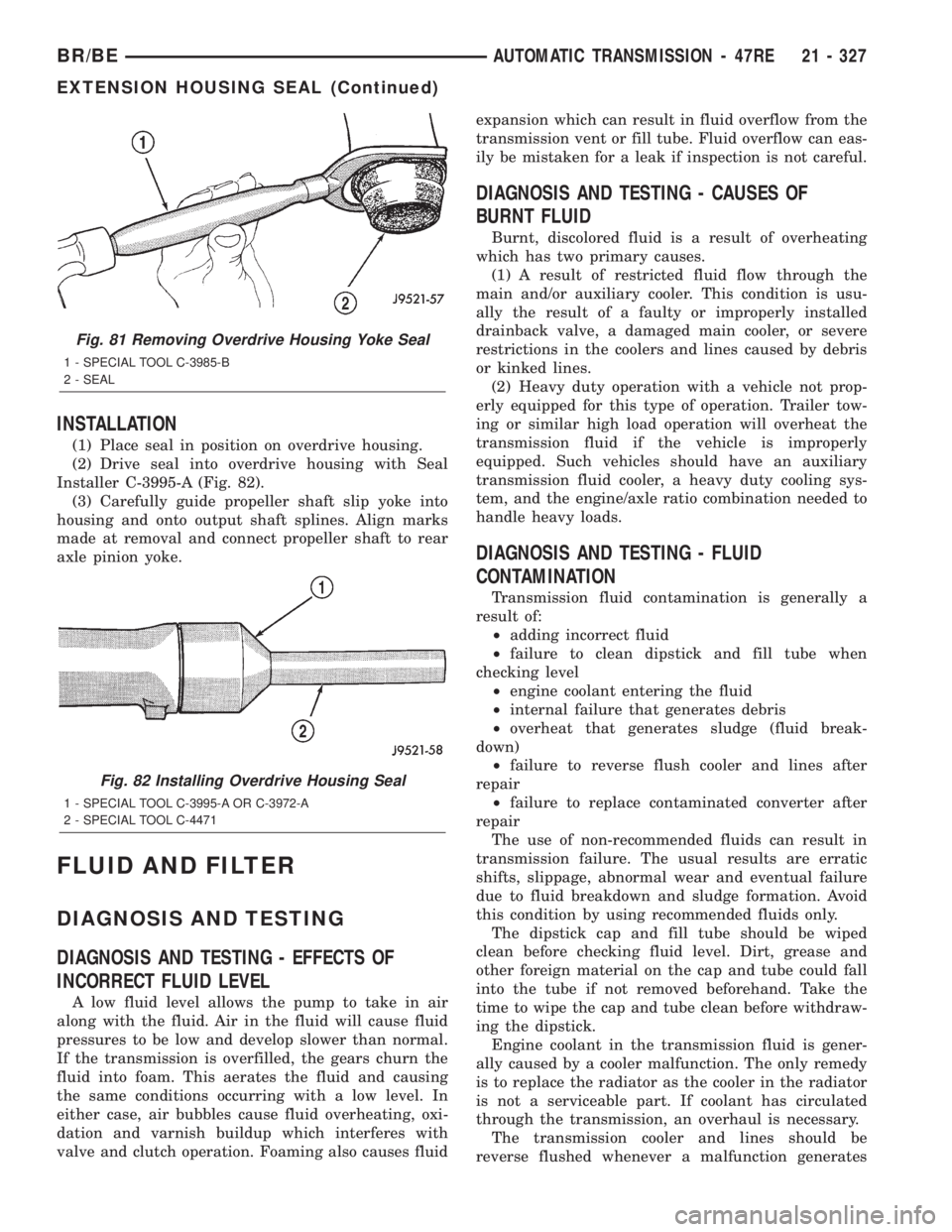
INSTALLATION
(1) Place seal in position on overdrive housing.
(2) Drive seal into overdrive housing with Seal
Installer C-3995-A (Fig. 82).
(3) Carefully guide propeller shaft slip yoke into
housing and onto output shaft splines. Align marks
made at removal and connect propeller shaft to rear
axle pinion yoke.
FLUID AND FILTER
DIAGNOSIS AND TESTING
DIAGNOSIS AND TESTING - EFFECTS OF
INCORRECT FLUID LEVEL
A low fluid level allows the pump to take in air
along with the fluid. Air in the fluid will cause fluid
pressures to be low and develop slower than normal.
If the transmission is overfilled, the gears churn the
fluid into foam. This aerates the fluid and causing
the same conditions occurring with a low level. In
either case, air bubbles cause fluid overheating, oxi-
dation and varnish buildup which interferes with
valve and clutch operation. Foaming also causes fluidexpansion which can result in fluid overflow from the
transmission vent or fill tube. Fluid overflow can eas-
ily be mistaken for a leak if inspection is not careful.
DIAGNOSIS AND TESTING - CAUSES OF
BURNT FLUID
Burnt, discolored fluid is a result of overheating
which has two primary causes.
(1) A result of restricted fluid flow through the
main and/or auxiliary cooler. This condition is usu-
ally the result of a faulty or improperly installed
drainback valve, a damaged main cooler, or severe
restrictions in the coolers and lines caused by debris
or kinked lines.
(2) Heavy duty operation with a vehicle not prop-
erly equipped for this type of operation. Trailer tow-
ing or similar high load operation will overheat the
transmission fluid if the vehicle is improperly
equipped. Such vehicles should have an auxiliary
transmission fluid cooler, a heavy duty cooling sys-
tem, and the engine/axle ratio combination needed to
handle heavy loads.
DIAGNOSIS AND TESTING - FLUID
CONTAMINATION
Transmission fluid contamination is generally a
result of:
²adding incorrect fluid
²failure to clean dipstick and fill tube when
checking level
²engine coolant entering the fluid
²internal failure that generates debris
²overheat that generates sludge (fluid break-
down)
²failure to reverse flush cooler and lines after
repair
²failure to replace contaminated converter after
repair
The use of non-recommended fluids can result in
transmission failure. The usual results are erratic
shifts, slippage, abnormal wear and eventual failure
due to fluid breakdown and sludge formation. Avoid
this condition by using recommended fluids only.
The dipstick cap and fill tube should be wiped
clean before checking fluid level. Dirt, grease and
other foreign material on the cap and tube could fall
into the tube if not removed beforehand. Take the
time to wipe the cap and tube clean before withdraw-
ing the dipstick.
Engine coolant in the transmission fluid is gener-
ally caused by a cooler malfunction. The only remedy
is to replace the radiator as the cooler in the radiator
is not a serviceable part. If coolant has circulated
through the transmission, an overhaul is necessary.
The transmission cooler and lines should be
reverse flushed whenever a malfunction generates
Fig. 81 Removing Overdrive Housing Yoke Seal
1 - SPECIAL TOOL C-3985-B
2 - SEAL
Fig. 82 Installing Overdrive Housing Seal
1 - SPECIAL TOOL C-3995-A OR C-3972-A
2 - SPECIAL TOOL C-4471
BR/BEAUTOMATIC TRANSMISSION - 47RE 21 - 327
EXTENSION HOUSING SEAL (Continued)
Page 1967 of 2255
STUDS
REMOVAL
(1) Raise and support the vehicle.
(2) Remove the wheel and tire assembly.
(3) Remove the brake caliper, caliper adapter and
rotor, (Refer to 5 - BRAKES/HYDRAULIC/MECHAN-
ICAL/ROTORS - REMOVAL).
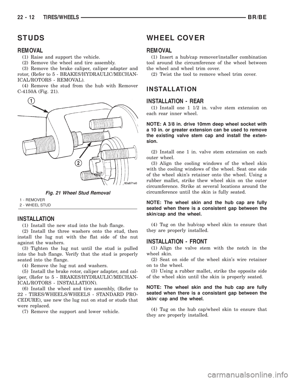
(4) Remove the stud from the hub with Remover
C-4150A (Fig. 21).
INSTALLATION
(1) Install the new stud into the hub flange.
(2) Install the three washers onto the stud, then
install the lug nut with the flat side of the nut
against the washers.
(3) Tighten the lug nut until the stud is pulled
into the hub flange. Verify that the stud is properly
seated into the flange.
(4) Remove the lug nut and washers.
(5) Install the brake rotor, caliper adapter, and cal-
iper, (Refer to 5 - BRAKES/HYDRAULIC/MECHAN-
ICAL/ROTORS - INSTALLATION).
(6) Install the wheel and tire assembly, (Refer to
22 - TIRES/WHEELS/WHEELS - STANDARD PRO-
CEDURE), use new the lug nut on stud or studs that
were replaced.
(7) Remove the support and lower vehicle.
WHEEL COVER
REMOVAL
(1) Insert a hub/cap remover/installer combination
tool around the circumference of the wheel between
the wheel and wheel trim cover.
(2) Twist the tool to remove wheel trim cover.
INSTALLATION
INSTALLATION - REAR
(1) Install one 1 1/2 in. valve stem extension on
each rear inner wheel.
NOTE: A 3/8 in. drive 10mm deep wheel socket with
a 10 in. or greater extension can be used to remove
the existing valve stem cap and install the exten-
sion.
(2) Install one 1 in. valve stem extension on each
outer wheel.
(3) Align the cooling windows of the wheel skin
with the cooling windows of the wheel. Seat one side
of the wheel skin's retainer onto the wheel. Using a
rubber mallet, strike thew wheel skin on the outer
circumference. Strike at several locations around the
circumference until the skin is fully seated.
NOTE: The wheel skin and the hub cap are fully
seated when there is a consistent gap between the
skin/cap and the wheel.
(4) Tug on the hub/cap wheel skin to ensure that
they are properly installed.
INSTALLATION - FRONT
(1) Align the valve stem with the notch in the
wheel skin.
(2) Seat on side of the wheel skin's wire retainer
on to the wheel.
(3) Using a rubber mallet, strike the opposite side
of the wheel skin until the skin is properly seated.
NOTE: The wheel skin and the hub cap are fully
seated when there is a consistant gap between the
skin/ cap and the wheel.
(4) Tug on the hub cap/wheel skin to ensure that
they are properly installed.
Fig. 21 Wheel Stud Removal
1 - REMOVER
2 - WHEEL STUD
22 - 12 TIRES/WHEELSBR/BE
Page 2122 of 2255
HEATING & AIR CONDITIONING
TABLE OF CONTENTS
page page
HEATING & AIR CONDITIONING
DESCRIPTION...........................1
OPERATION.............................1
DIAGNOSIS AND TESTING
DIAGNOSIS AND TESTING - A/C
PERFORMANCE........................2
DIAGNOSIS AND TESTING - HEATER
PERFORMANCE........................6STANDARD PROCEDURE
STANDARD PROCEDURE - DIODE
REPLACEMENT.........................7
SPECIFICATIONS.........................7
CONTROLS.............................9
DISTRIBUTION..........................30
PLUMBING.............................40
HEATING & AIR
CONDITIONING
DESCRIPTION - HEATER AND AIR
CONDITIONER
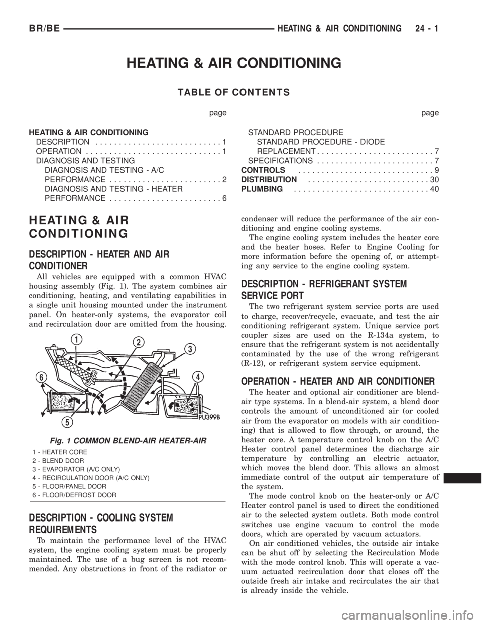
All vehicles are equipped with a common HVAC
housing assembly (Fig. 1). The system combines air
conditioning, heating, and ventilating capabilities in
a single unit housing mounted under the instrument
panel. On heater-only systems, the evaporator coil
and recirculation door are omitted from the housing.
DESCRIPTION - COOLING SYSTEM
REQUIREMENTS
To maintain the performance level of the HVAC
system, the engine cooling system must be properly
maintained. The use of a bug screen is not recom-
mended. Any obstructions in front of the radiator orcondenser will reduce the performance of the air con-
ditioning and engine cooling systems.
The engine cooling system includes the heater core
and the heater hoses. Refer to Engine Cooling for
more information before the opening of, or attempt-
ing any service to the engine cooling system.
DESCRIPTION - REFRIGERANT SYSTEM
SERVICE PORT
The two refrigerant system service ports are used
to charge, recover/recycle, evacuate, and test the air
conditioning refrigerant system. Unique service port
coupler sizes are used on the R-134a system, to
ensure that the refrigerant system is not accidentally
contaminated by the use of the wrong refrigerant
(R-12), or refrigerant system service equipment.
OPERATION - HEATER AND AIR CONDITIONER
The heater and optional air conditioner are blend-
air type systems. In a blend-air system, a blend door
controls the amount of unconditioned air (or cooled
air from the evaporator on models with air condition-
ing) that is allowed to flow through, or around, the
heater core. A temperature control knob on the A/C
Heater control panel determines the discharge air
temperature by controlling an electric actuator,
which moves the blend door. This allows an almost
immediate control of the output air temperature of
the system.
The mode control knob on the heater-only or A/C
Heater control panel is used to direct the conditioned
air to the selected system outlets. Both mode control
switches use engine vacuum to control the mode
doors, which are operated by vacuum actuators.
On air conditioned vehicles, the outside air intake
can be shut off by selecting the Recirculation Mode
with the mode control knob. This will operate a vac-
uum actuated recirculation door that closes off the
outside fresh air intake and recirculates the air that
is already inside the vehicle.
Fig. 1 COMMON BLEND-AIR HEATER-AIR
1 - HEATER CORE
2 - BLEND DOOR
3 - EVAPORATOR (A/C ONLY)
4 - RECIRCULATION DOOR (A/C ONLY)
5 - FLOOR/PANEL DOOR
6 - FLOOR/DEFROST DOOR
BR/BEHEATING & AIR CONDITIONING 24 - 1