2002 DODGE RAM cooling
[x] Cancel search: coolingPage 1265 of 2255
(8) Remove viscous fan/drive assembly (Refer to 7 -
COOLING/ENGINE/RADIATOR FAN - REMOVAL).
(9) Remove the accessory drive belt (Refer to 7 -
COOLING/ACCESSORY DRIVE/DRIVE BELTS -
REMOVAL).
(10) Remove the cooling fan support/hub from the
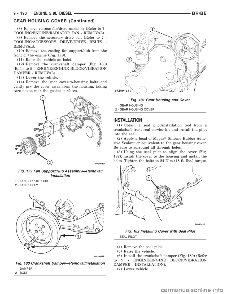
front of the engine (Fig. 179).
(11) Raise the vehicle on hoist.
(12) Remove the crankshaft damper (Fig. 180)
(Refer to 9 - ENGINE/ENGINE BLOCK/VIBRATION
DAMPER - REMOVAL).
(13) Lower the vehicle.
(14) Remove the gear cover-to-housing bolts and
gently pry the cover away from the housing, taking
care not to mar the gasket surfaces.
INSTALLATION
(1) Obtain a seal pilot/installation tool from a
crankshaft front seal service kit and install the pilot
into the seal.
(2) Apply a bead of MopartSilicone Rubber Adhe-
sive Sealant or equivalent to the gear housing cover.
Be sure to surround all through holes.
(3) Using the seal pilot to align the cover (Fig.
182), install the cover to the housing and install the
bolts. Tighten the bolts to 24 N´m (18 ft. lbs.) torque.
(4) Remove the seal pilot.
(5) Raise the vehicle.
(6) Install the crankshaft damper (Fig. 180) (Refer
to 9 - ENGINE/ENGINE BLOCK/VIBRATION
DAMPER - INSTALLATION).
(7) Lower vehicle.
Fig. 179 Fan Support/Hub AssemblyÐRemoval/
Installation
1 - FAN SUPPORT/HUB
2 - FAN PULLEY
Fig. 180 Crankshaft DamperÐRemoval/Installation
1 - DAMPER
2 - BOLT
Fig. 181 Gear Housing and Cover
1 - GEAR HOUSING
2 - GEAR HOUSING COVER
Fig. 182 Installing Cover with Seal Pilot
1 - SEAL PILOT
9 - 190 ENGINE 5.9L DIESELBR/BE
GEAR HOUSING COVER (Continued)
Page 1266 of 2255
(8) Install the fan support/hub assy. (Fig. 179) and
tighten bolts to 24 N´m (18 ft. lbs.) torque.
(9) Install the accessory drive belt (Refer to 7 -
COOLING/ACCESSORY DRIVE/DRIVE BELTS -
INSTALLATION).
(10) Install the cooling fan and shroud together
(Refer to 7 - COOLING/ENGINE/RADIATOR FAN -
INSTALLATION).
(11) Install the windshield washer reservoir to the
fan shroud and connect the washer pump supply
hose and electrical connection.(12) Install the coolant recovery bottle to the fan
shroud and connect the hose to the radiator filler
neck.
(13) Install the radiator upper hose and clamps.
(14) Add coolant (Refer to 7 - COOLING - STAN-
DARD PROCEDURE).
(15) Connect the battery cables.
(16) Start engine and inspect for leaks.
BR/BEENGINE 5.9L DIESEL 9 - 191
GEAR HOUSING COVER (Continued)
Page 1286 of 2255
(4) Discharge the A/C system (Refer to 24 - HEAT-
ING & AIR CONDITIONING/PLUMBING - STAN-
DARD PROCEDURE) and remove the A/C condenser
(Refer to 24 - HEATING & AIR CONDITIONING/
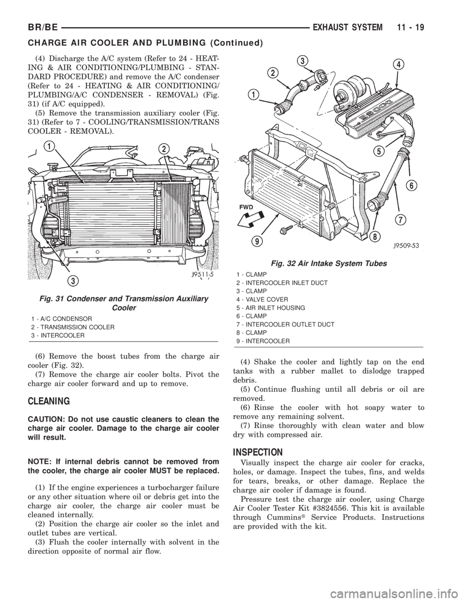
PLUMBING/A/C CONDENSER - REMOVAL) (Fig.
31) (if A/C equipped).
(5) Remove the transmission auxiliary cooler (Fig.
31) (Refer to 7 - COOLING/TRANSMISSION/TRANS
COOLER - REMOVAL).
(6) Remove the boost tubes from the charge air
cooler (Fig. 32).
(7) Remove the charge air cooler bolts. Pivot the
charge air cooler forward and up to remove.
CLEANING
CAUTION: Do not use caustic cleaners to clean the
charge air cooler. Damage to the charge air cooler
will result.
NOTE: If internal debris cannot be removed from
the cooler, the charge air cooler MUST be replaced.
(1) If the engine experiences a turbocharger failure
or any other situation where oil or debris get into the
charge air cooler, the charge air cooler must be
cleaned internally.
(2) Position the charge air cooler so the inlet and
outlet tubes are vertical.
(3) Flush the cooler internally with solvent in the
direction opposite of normal air flow.(4) Shake the cooler and lightly tap on the end
tanks with a rubber mallet to dislodge trapped
debris.
(5) Continue flushing until all debris or oil are
removed.
(6) Rinse the cooler with hot soapy water to
remove any remaining solvent.
(7) Rinse thoroughly with clean water and blow
dry with compressed air.
INSPECTION
Visually inspect the charge air cooler for cracks,
holes, or damage. Inspect the tubes, fins, and welds
for tears, breaks, or other damage. Replace the
charge air cooler if damage is found.
Pressure test the charge air cooler, using Charge
Air Cooler Tester Kit #3824556. This kit is available
through CumminstService Products. Instructions
are provided with the kit.
Fig. 31 Condenser and Transmission Auxiliary
Cooler
1 - A/C CONDENSOR
2 - TRANSMISSION COOLER
3 - INTERCOOLER
Fig. 32 Air Intake System Tubes
1 - CLAMP
2 - INTERCOOLER INLET DUCT
3 - CLAMP
4 - VALVE COVER
5 - AIR INLET HOUSING
6 - CLAMP
7 - INTERCOOLER OUTLET DUCT
8 - CLAMP
9 - INTERCOOLER
BR/BEEXHAUST SYSTEM 11 - 19
CHARGE AIR COOLER AND PLUMBING (Continued)
Page 1287 of 2255
INSTALLATION
(1) Position the charge air cooler. Install the bolts
and tighten to 2 N´m (17 in. lbs.) torque.
(2) Install the air intake system tubes to the
charge air cooler. With the clamps in position, tighten
the clamps to 11 N´m (95 in. lbs.) torque.
(3) Install the transmission auxiliary cooler (if
equipped) (Refer to 7 - COOLING/TRANSMISSION/
TRANS COOLER - INSTALLATION).
(4) Install the A/C condenser (if A/C equipped)
(Refer to 24 - HEATING & AIR CONDITIONING/
PLUMBING/A/C CONDENSER - INSTALLATION).Recharge A/C system (Refer to 24 - HEATING & AIR
CONDITIONING/PLUMBING - STANDARD PRO-
CEDURE).
(5) Install the front support bracket. Install and
tighten the bolts.
(6) Install the front bumper (Refer to 13 -
FRAMES & BUMPERS/BUMPERS/FRONT
BUMPER - INSTALLATION).
(7) Connect the battery negative cables.
(8) Start engine and check for boost system leaks.
11 - 20 EXHAUST SYSTEMBR/BE
CHARGE AIR COOLER AND PLUMBING (Continued)
Page 1369 of 2255
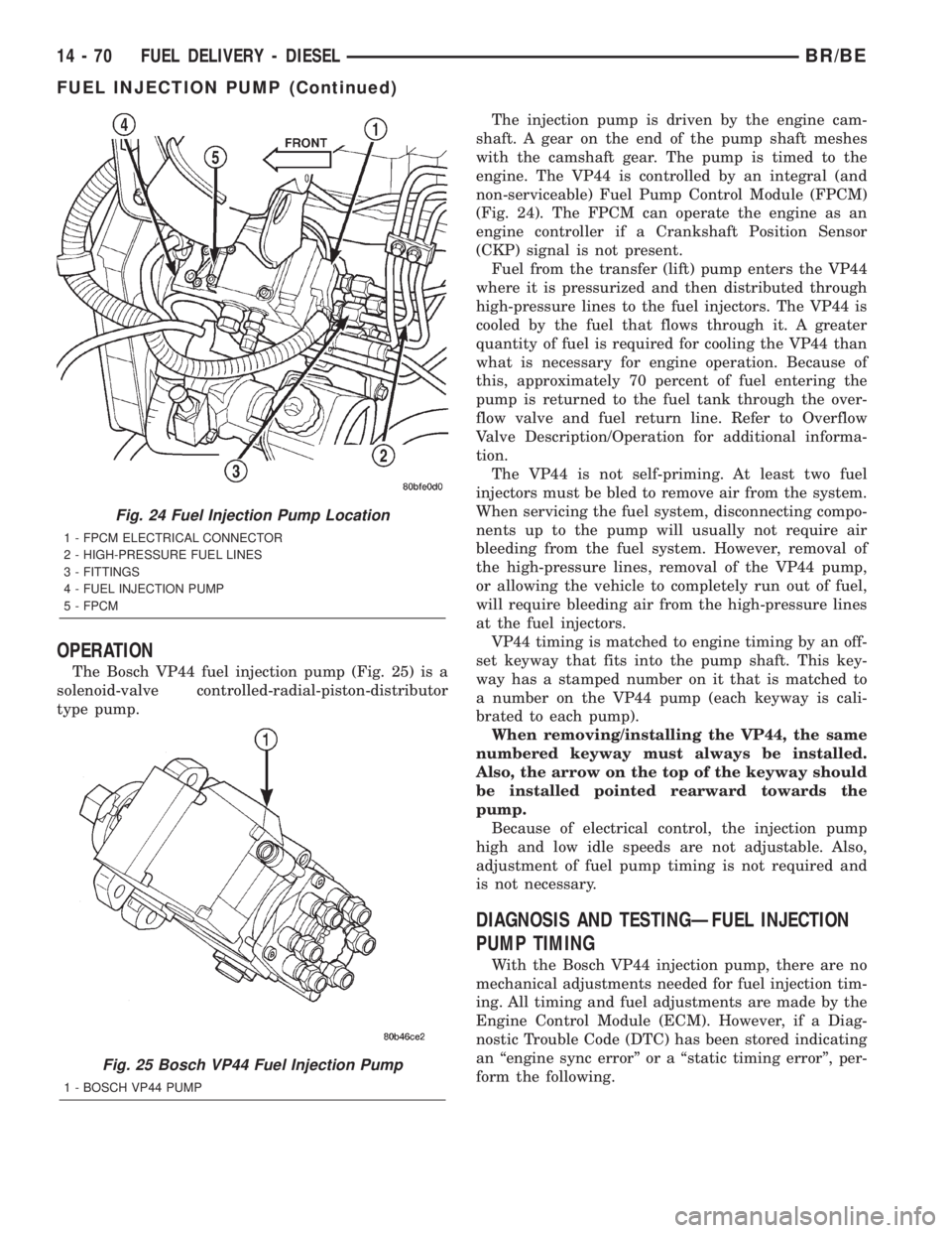
OPERATION
The Bosch VP44 fuel injection pump (Fig. 25) is a
solenoid-valve controlled-radial-piston-distributor
type pump.The injection pump is driven by the engine cam-
shaft. A gear on the end of the pump shaft meshes
with the camshaft gear. The pump is timed to the
engine. The VP44 is controlled by an integral (and
non-serviceable) Fuel Pump Control Module (FPCM)
(Fig. 24). The FPCM can operate the engine as an
engine controller if a Crankshaft Position Sensor
(CKP) signal is not present.
Fuel from the transfer (lift) pump enters the VP44
where it is pressurized and then distributed through
high-pressure lines to the fuel injectors. The VP44 is
cooled by the fuel that flows through it. A greater
quantity of fuel is required for cooling the VP44 than
what is necessary for engine operation. Because of
this, approximately 70 percent of fuel entering the
pump is returned to the fuel tank through the over-
flow valve and fuel return line. Refer to Overflow
Valve Description/Operation for additional informa-
tion.
The VP44 is not self-priming. At least two fuel
injectors must be bled to remove air from the system.
When servicing the fuel system, disconnecting compo-
nents up to the pump will usually not require air
bleeding from the fuel system. However, removal of
the high-pressure lines, removal of the VP44 pump,
or allowing the vehicle to completely run out of fuel,
will require bleeding air from the high-pressure lines
at the fuel injectors.
VP44 timing is matched to engine timing by an off-
set keyway that fits into the pump shaft. This key-
way has a stamped number on it that is matched to
a number on the VP44 pump (each keyway is cali-
brated to each pump).
When removing/installing the VP44, the same
numbered keyway must always be installed.
Also, the arrow on the top of the keyway should
be installed pointed rearward towards the
pump.
Because of electrical control, the injection pump
high and low idle speeds are not adjustable. Also,
adjustment of fuel pump timing is not required and
is not necessary.
DIAGNOSIS AND TESTINGÐFUEL INJECTION
PUMP TIMING
With the Bosch VP44 injection pump, there are no
mechanical adjustments needed for fuel injection tim-
ing. All timing and fuel adjustments are made by the
Engine Control Module (ECM). However, if a Diag-
nostic Trouble Code (DTC) has been stored indicating
an ªengine sync errorº or a ªstatic timing errorº, per-
form the following.
Fig. 24 Fuel Injection Pump Location
1 - FPCM ELECTRICAL CONNECTOR
2 - HIGH-PRESSURE FUEL LINES
3 - FITTINGS
4 - FUEL INJECTION PUMP
5 - FPCM
Fig. 25 Bosch VP44 Fuel Injection Pump
1 - BOSCH VP44 PUMP
14 - 70 FUEL DELIVERY - DIESELBR/BE
FUEL INJECTION PUMP (Continued)
Page 1385 of 2255
(7) Because fuel pump relay was removed, a Diag-
nostic Trouble Code (DTC) may have been set. After
testing is completed, and relay has been installed,
use DRB scan tool to remove DTC.
Fuel Supply Restriction Test:
Due to very small vacuum specifications, the DRB
scan tool along with the Periphal Expansion Port
(PEP) Module and 0±15 psi transducer must be used.
(8) Verify transfer pump pressure is OK before
performing restriction test.
(9) Locate and disconnect fuel supply line quick-
connect fitting at left-rear of engine (Fig. 63). After
disconnecting line, plastic clip will remain attached
to metal fuel line at engine. Carefully remove clip
from metal line. Snap same clip into fuel supply
hose.
(10) Install Special Rubber Adapter Hose Tool
6631 (3/8º) into ends of disconnected fuel supply line.
(11) Install transducer from PEP module to brass
ªTº fitting on tool 6631.
(12) Hook up DRB scan tool to transducer.
WARNING: DO NOT STAND IN LINE WITH THE
COOLING FAN FOR THE FOLLOWING STEPS.
(13) Start engine and record vacuum reading with
engine speed at high-idle (high-idle means engine
speed is at 100 percent throttle and no load). The
fuel restriction testMUSTbe done with engine speed
at high-idle.
(14) If vacuum reading islessthan 6 in/hg. (0±152
mm hg.), test is OK. If vacuum reading ishigher
than 6 in/hg. (152 mm hg.), restriction exists in fuel
supply line or in fuel tank module. Check fuel supply
line for damage, dents or kinking. If OK, remove
module and check module and lines for blockage.
Also check fuel pump inlet filter at bottom of module
for obstructions.
Testing For Air Leaks in Fuel Supply Side:
(15) A 3±foot section of 3/8º I.D. clear tubing is
required for this test.
(16) Using a tire core valve removal tool, carefully
remove core valve from inlet fitting test port.
(17) Attach and clamp the 3/8ºclear hose to fitting
nipple.
(18) Place other end of hose into a large clear con-
tainer. Allow hose to loop as high as possibleabove
test port.
(19) The fuel transfer pump can be put into a 25
second run (test) mode if key is quickly turned to
crank position and released back to run position
without starting engine.
To prevent engine from starting in this test, first
remove fuel system relay (fuel injection pump relay).
Relay is located in Power Distribution Center (PDC).
Refer to label under PDC cover for relay location.
Because fuel pump relay was removed, a DiagnosticTrouble Code (DTC) may have been set. After testing
is completed, and relay has been installed, use DRB
scan tool to remove DTC.
(20) Allow air to purge from empty hose before
examining for air bubbles. Air bubbles should not be
present.
(21) If bubbles are present, check for leaks in sup-
ply line to fuel tank.
(22) If supply line is not leaking, remove fuel tank
module and remove filter at bottom of module (filter
snaps to module). Check for leaks between supply
nipple at top of module, and filter opening at bottom
of module. Replace module if necessary.
(23) After performing test, install core back into
test fitting. Before installing protective cap, be sure
fitting is not leaking.
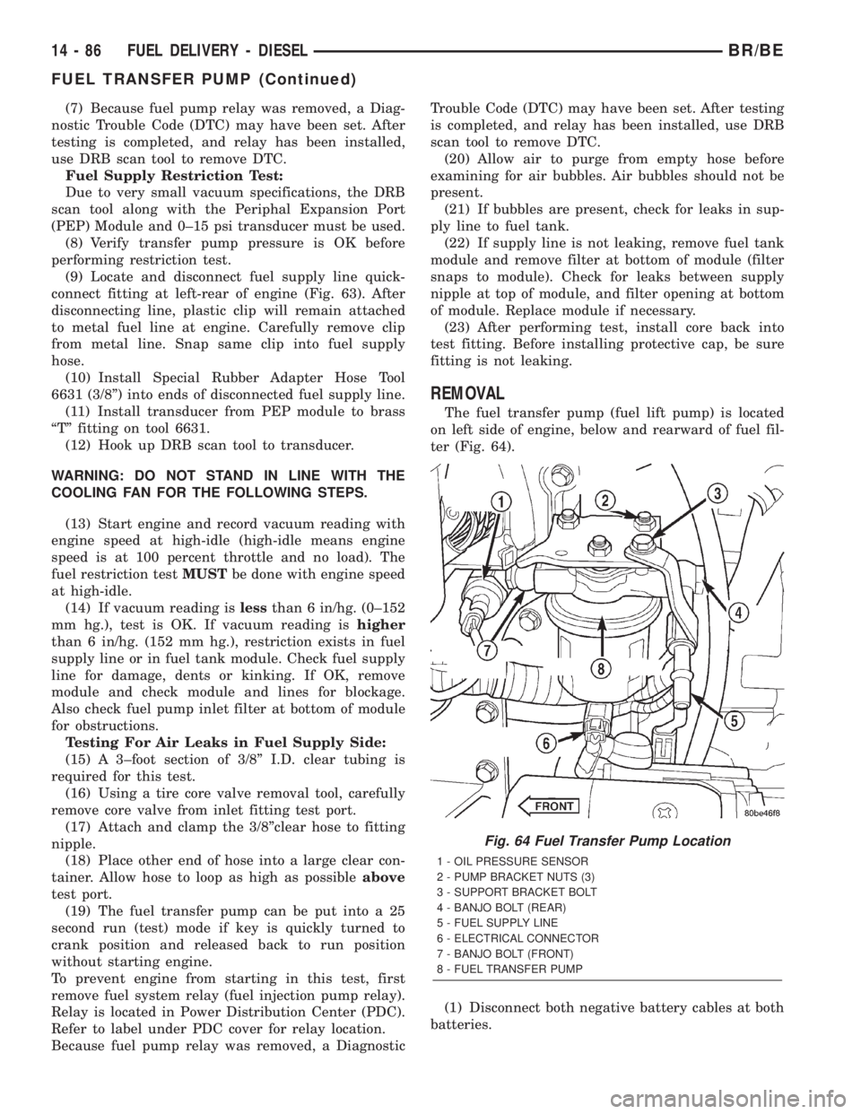
REMOVAL
The fuel transfer pump (fuel lift pump) is located
on left side of engine, below and rearward of fuel fil-
ter (Fig. 64).
(1) Disconnect both negative battery cables at both
batteries.
Fig. 64 Fuel Transfer Pump Location
1 - OIL PRESSURE SENSOR
2 - PUMP BRACKET NUTS (3)
3 - SUPPORT BRACKET BOLT
4 - BANJO BOLT (REAR)
5 - FUEL SUPPLY LINE
6 - ELECTRICAL CONNECTOR
7 - BANJO BOLT (FRONT)
8 - FUEL TRANSFER PUMP
14 - 86 FUEL DELIVERY - DIESELBR/BE
FUEL TRANSFER PUMP (Continued)
Page 1444 of 2255
(3) Plug the return line port/ports at the pump.
(4) Position the return line/lines into a large con-
tainer to catch the fluid.
(5) While an assistant is filling the pump reservoir
start the engine.
(6) With the engine running at idle turn the wheel
back and forth.
NOTE: Do not contact or hold the wheel against the
steering stops.
(7) Run a quart of fluid through the system then
stop the engine and install the return line/lines.
(8) Fill the system with fluid and perform Steering
Pump Initial Operation, (Refer to 19 - STEERING/
PUMP - STANDARD PROCEDURE).
(9) Start the engine and run it for fifteen minutes
then stop the engine.
(10) Remove the return line/lines from the pump
and plug the pump port/ports.
(11) Pour fresh fluid into the reservoir and check
the draining fluid for contamination. If the fluid is
still contaminated, disassemble and clean the steer-
ing gear and flush the system again.
(12) Install the return line/lines and perform
Steering Pump Initial Operation, (Refer to 19 -
STEERING/PUMP - STANDARD PROCEDURE).
REMOVAL
REMOVAL - GASOLINE ENGINE
(1) Remove the serpentine drive belt, (Refer to 7 -
COOLING/ACCESSORY DRIVE/DRIVE BELTS -
REMOVAL) OR (Refer to 7 - COOLING/ACCESSORY
DRIVE/DRIVE BELTS - REMOVAL).
(2) Remove the hoses from the power steering
pump and cap the fittings.
(3) Remove battery ground cable and unthread
stud from cylinder head, do not remove from bracket.
(4) Loosen upper bracket bolt and remove the
lower bracket to engine block bolts.
(5) Pivot the pump assembly past the coolant tube.
(6) Remove the upper stud and remove upper bolt
from cylinder head.
(7) Remove steering pump and mounting bracket
from engine as an assembly.
(8) Remove the pump pulley with Puller C-4333, to
access pump attaching bolts, (Refer to 19 - STEER-
ING/PUMP/PULLEY - REMOVAL).
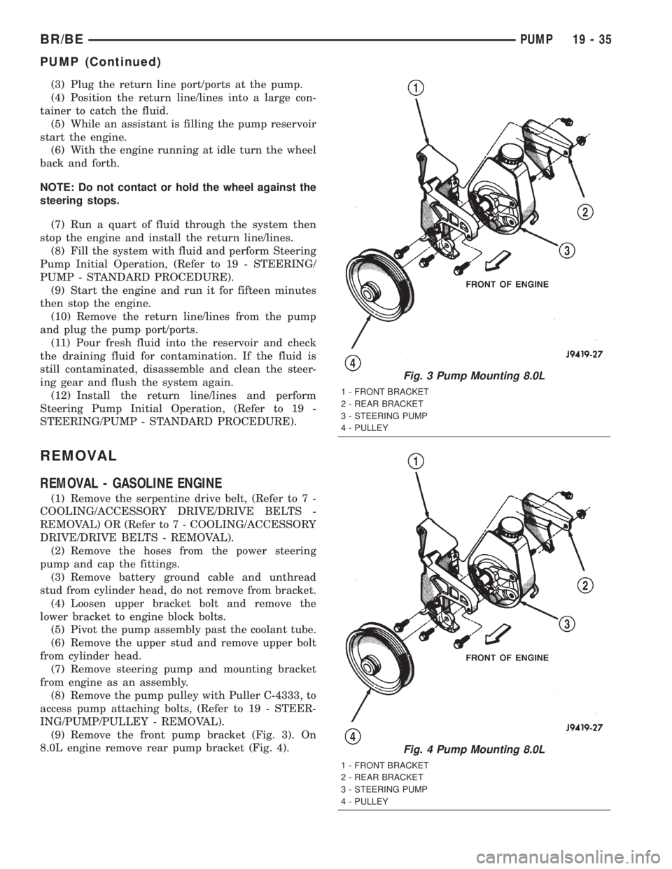
(9) Remove the front pump bracket (Fig. 3). On
8.0L engine remove rear pump bracket (Fig. 4).
Fig. 3 Pump Mounting 8.0L
1 - FRONT BRACKET
2 - REAR BRACKET
3 - STEERING PUMP
4 - PULLEY
Fig. 4 Pump Mounting 8.0L
1 - FRONT BRACKET
2 - REAR BRACKET
3 - STEERING PUMP
4 - PULLEY
BR/BEPUMP 19 - 35
PUMP (Continued)
Page 1445 of 2255
REMOVAL - DIESEL ENGINE
(1) Remove and cap steering pump hoses and vac-
uum pump vacuum line.
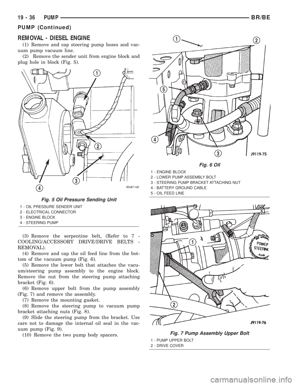
(2) Remove the sender unit from engine block and
plug hole in block (Fig. 5).
(3) Remove the serpentine belt, (Refer to 7 -
COOLING/ACCESSORY DRIVE/DRIVE BELTS -
REMOVAL).
(4) Remove and cap the oil feed line from the bot-
tom of the vacuum pump (Fig. 6).
(5) Remove the lower bolt that attaches the vacu-
um/steering pump assembly to the engine block.
Remove the nut from the steering pump attaching
bracket (Fig. 6).
(6) Remove upper bolt from the pump assembly
(Fig. 7) and remove the assembly.
(7) Remove the mounting gasket.
(8) Remove the steering pump to vacuum pump
bracket attaching nuts (Fig. 8).
(9) Slide the steering pump from the bracket. Use
care not to damage the internal oil seal in the vac-
uum pump (Fig. 9).
(10) Remove the two pump body spacers.
Fig. 5 Oil Pressure Sending Unit
1 - OIL PRESSURE SENDER UNIT
2 - ELECTRICAL CONNECTOR
3 - ENGINE BLOCK
4 - STEERING PUMP
Fig. 6 Oil
1 - ENGINE BLOCK
2 - LOWER PUMP ASSEMBLY BOLT
3 - STEERING PUMP BRACKET ATTACHING NUT
4 - BATTERY GROUND CABLE
5 - OIL FEED LINE
Fig. 7 Pump Assembly Upper Bolt
1 - PUMP UPPER BOLT
2 - DRIVE COVER
19 - 36 PUMPBR/BE
PUMP (Continued)