2002 DODGE RAM cooling
[x] Cancel search: coolingPage 1220 of 2255
original locations (Fig. 53). Tighten bolts to 36 N´m
(27 ft. lbs.) torque.
(4)Verify valve lash adjustment (Refer to 9 -
ENGINE/CYLINDER HEAD/INTAKE/EXHAUST
VALVES & SEATS - STANDARD PROCEDURE).
(5) Install cylinder head cover and reusable gasket
(Fig. 52) (Refer to 9 - ENGINE/CYLINDER HEAD/
CYLINDER HEAD COVER(S) - INSTALLATION).
(6) Install the accessory drive belt (Refer to 7 -
COOLING/ACCESSORY DRIVE/DRIVE BELTS -
INSTALLATION).
(7) Connect battery negative cables.
ROCKER ARM / ADJUSTER
ASSY
DESCRIPTION
The 24±valve overhead system incorporates rocker
arms that are designed to allow fuel injector service
without removing the rocker arms and pedestals. The
unique intake and exhaust rocker arms have their
own rocker shafts and are lubricated by passages
intersecting the cylinder block main oil rifle. Cross-
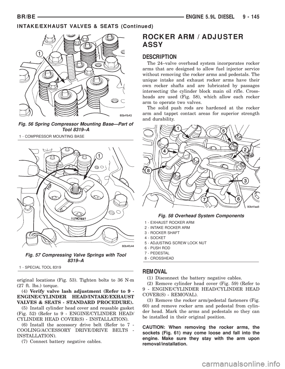
heads are used (Fig. 58), which allow each rocker
arm to operate two valves.
The solid push rods are hardened at the rocker
arm and tappet contact areas for superior strength
and durability.
REMOVAL
(1) Disconnect the battery negative cables.
(2) Remove cylinder head cover (Fig. 59) (Refer to
9 - ENGINE/CYLINDER HEAD/CYLINDER HEAD
COVER(S) - REMOVAL).
(3) Remove the rocker arm/pedestal fasteners (Fig.
60) and remove rocker arm and pedestal from cylin-
der head. Mark the arms and pedestals so they can
be installed in their original position.
CAUTION: When removing the rocker arms, the
sockets (Fig. 61) may come loose and fall into the
engine. Make sure they stay with the arm upon
removal/installation.
Fig. 56 Spring Compressor Mounting BaseÐPart of
Tool 8319±A
1 - COMPRESSOR MOUNTING BASE
Fig. 57 Compressing Valve Springs with Tool
8319±A
1 - SPECIAL TOOL 8319
Fig. 58 Overhead System Components
1 - EXHAUST ROCKER ARM
2 - INTAKE ROCKER ARM
3 - ROCKER SHAFT
4 - SOCKET
5 - ADJUSTING SCREW LOCK NUT
6 - PUSH ROD
7 - PEDESTAL
8 - CROSSHEAD
BR/BEENGINE 5.9L DIESEL 9 - 145
INTAKE/EXHAUST VALVES & SEATS (Continued)
Page 1227 of 2255
Overall variation end to end or side to side is 0.075
mm (0.003 inch).
If the surface exceeds the limit, .
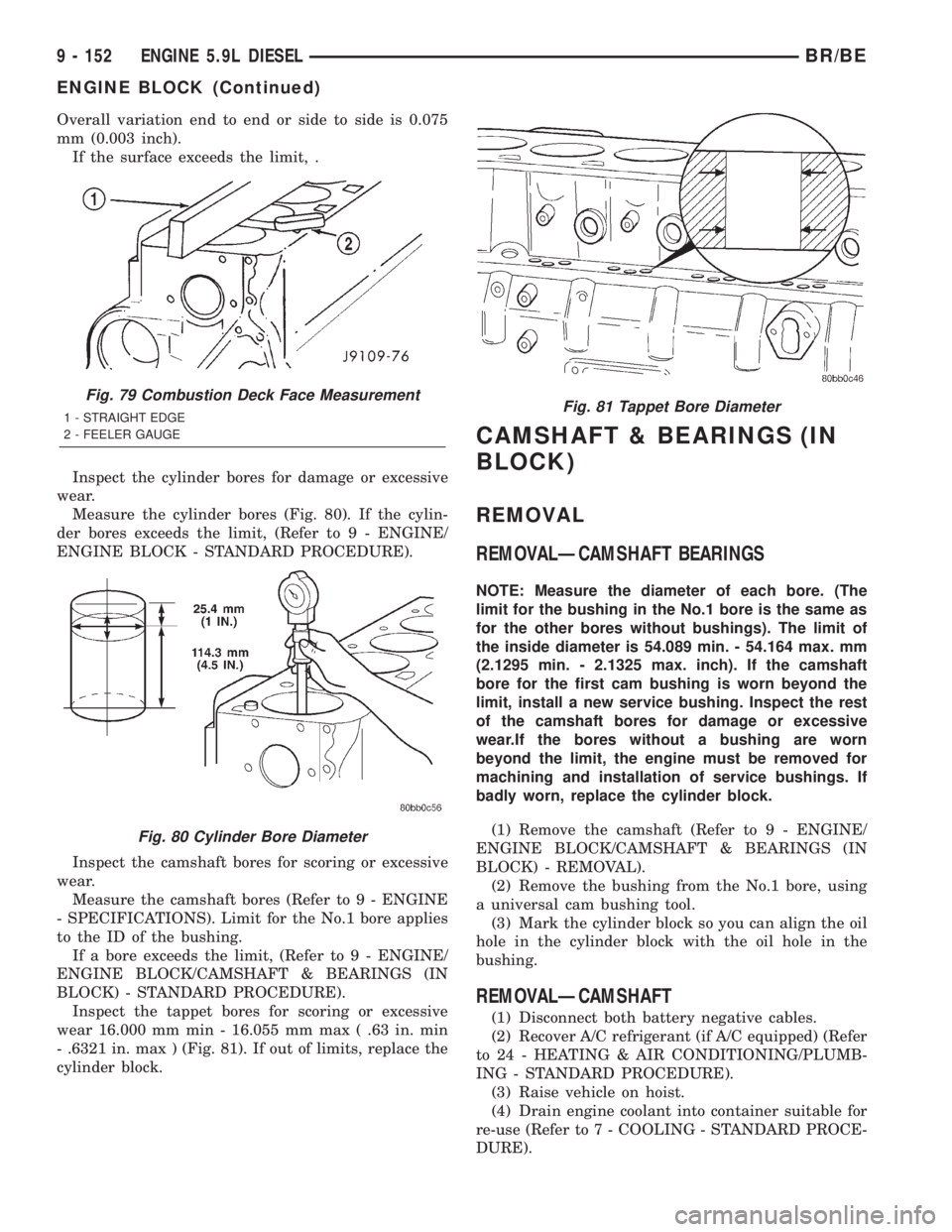
Inspect the cylinder bores for damage or excessive
wear.
Measure the cylinder bores (Fig. 80). If the cylin-
der bores exceeds the limit, (Refer to 9 - ENGINE/
ENGINE BLOCK - STANDARD PROCEDURE).
Inspect the camshaft bores for scoring or excessive
wear.
Measure the camshaft bores (Refer to 9 - ENGINE
- SPECIFICATIONS). Limit for the No.1 bore applies
to the ID of the bushing.
If a bore exceeds the limit, (Refer to 9 - ENGINE/
ENGINE BLOCK/CAMSHAFT & BEARINGS (IN
BLOCK) - STANDARD PROCEDURE).
Inspect the tappet bores for scoring or excessive
wear 16.000 mm min - 16.055 mm max ( .63 in. min
- .6321 in. max ) (Fig. 81). If out of limits, replace the
cylinder block.
CAMSHAFT & BEARINGS (IN
BLOCK)
REMOVAL
REMOVALÐCAMSHAFT BEARINGS
NOTE: Measure the diameter of each bore. (The
limit for the bushing in the No.1 bore is the same as
for the other bores without bushings). The limit of
the inside diameter is 54.089 min. - 54.164 max. mm
(2.1295 min. - 2.1325 max. inch). If the camshaft
bore for the first cam bushing is worn beyond the
limit, install a new service bushing. Inspect the rest
of the camshaft bores for damage or excessive
wear.If the bores without a bushing are worn
beyond the limit, the engine must be removed for
machining and installation of service bushings. If
badly worn, replace the cylinder block.
(1) Remove the camshaft (Refer to 9 - ENGINE/
ENGINE BLOCK/CAMSHAFT & BEARINGS (IN
BLOCK) - REMOVAL).
(2) Remove the bushing from the No.1 bore, using
a universal cam bushing tool.
(3) Mark the cylinder block so you can align the oil
hole in the cylinder block with the oil hole in the
bushing.
REMOVALÐCAMSHAFT
(1) Disconnect both battery negative cables.
(2) Recover A/C refrigerant (if A/C equipped) (Refer
to 24 - HEATING & AIR CONDITIONING/PLUMB-
ING - STANDARD PROCEDURE).
(3) Raise vehicle on hoist.
(4) Drain engine coolant into container suitable for
re-use (Refer to 7 - COOLING - STANDARD PROCE-
DURE).
Fig. 79 Combustion Deck Face Measurement
1 - STRAIGHT EDGE
2 - FEELER GAUGE
Fig. 80 Cylinder Bore Diameter
Fig. 81 Tappet Bore Diameter
9 - 152 ENGINE 5.9L DIESELBR/BE
ENGINE BLOCK (Continued)
Page 1228 of 2255
(5) Lower vehicle.
(6) Remove radiator upper hose.
(7) Remove viscous fan/drive assembly and fan
shroud (Refer to 7 - COOLING/ENGINE/RADIATOR
FAN - REMOVAL).
(8) Disconnect the coolant recovery bottle hose
from the radiator filler neck.
(9) Disconnect lower radiator hose from radiator
outlet.
(10)Automatic Transmission models:Discon-
nect transmission oil cooler lines from radiator using
Special Tool 6931 (unless equipped with finger-re-
lease disconnect).
(11) Remove radiator mounting screws and lift
radiator out of engine compartment.
(12) Remove upper radiator support panel.
(13) Remove front bumper assembly (Refer to 13 -
FRAMES & BUMPERS/BUMPERS/FRONT
BUMPER - REMOVAL).
(14) If A/C equipped, disconnect A/C condenser
refrigerant lines.
(15) Disconnect charge air cooler piping from the
cooler inlet and outlet.
(16) Remove the two charge air cooler mounting
bolts.
(17) Remove charge air cooler (and A/C condenser
if equipped) from vehicle.
(18) Remove accessory drive belt (Refer to 7 -
COOLING/ACCESSORY DRIVE/DRIVE BELTS -
REMOVAL).
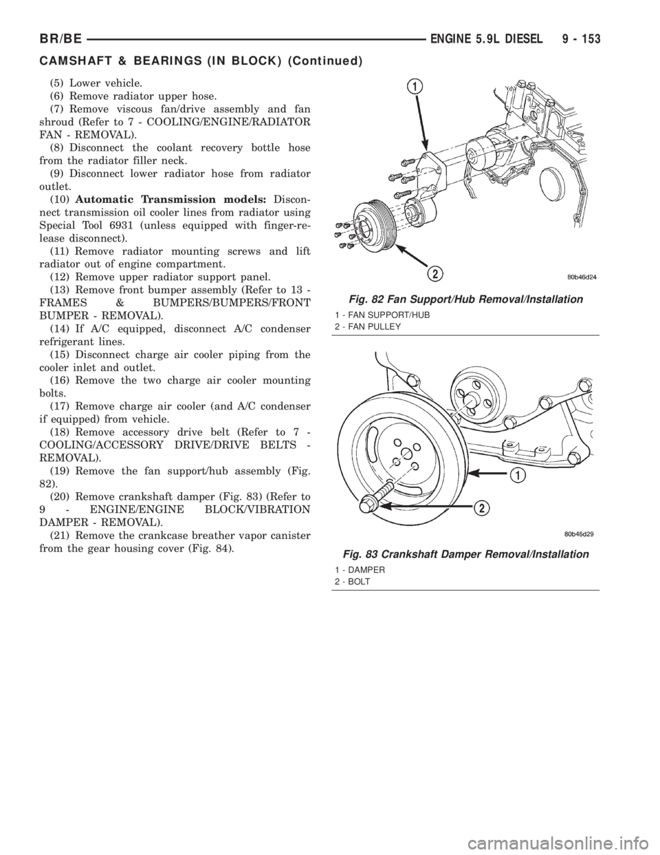
(19) Remove the fan support/hub assembly (Fig.
82).
(20) Remove crankshaft damper (Fig. 83) (Refer to
9 - ENGINE/ENGINE BLOCK/VIBRATION
DAMPER - REMOVAL).
(21) Remove the crankcase breather vapor canister
from the gear housing cover (Fig. 84).
Fig. 82 Fan Support/Hub Removal/Installation
1 - FAN SUPPORT/HUB
2 - FAN PULLEY
Fig. 83 Crankshaft Damper Removal/Installation
1 - DAMPER
2 - BOLT
BR/BEENGINE 5.9L DIESEL 9 - 153
CAMSHAFT & BEARINGS (IN BLOCK) (Continued)
Page 1233 of 2255
(11) Install the cylinder head cover and reusable
gasket (Fig. 85) (Refer to 9 - ENGINE/CYLINDER
HEAD/CYLINDER HEAD COVER(S) - INSTALLA-
TION).
(12) Install gear housing cover (Refer to 9 -
ENGINE/VALVE TIMING/GEAR HOUSING COVER
- INSTALLATION).
(13) Install the crankshaft damper (Fig. 83) (Refer
to 9 - ENGINE/ENGINE BLOCK/VIBRATION
DAMPER - INSTALLATION).
(14) Install the fan support/hub assembly (Fig. 82)
and tighten bolts to 24 N´m (18 ft. lbs.) torque.
(15) Install the crankcase breather housing (Refer
to 9 - ENGINE - INSTALLATION).
(16) Install the charge air cooler (with a/c con-
denser and auxiliary transmission oil cooler, if
equipped) and tighten the mounting bolts to 2 N´m
(17 in. lbs.) torque.
(17) Connect charge air cooler inlet and outlet
pipes. Tighten clamps to 10 N´m (100 in. lbs.) torque.
(18) Install the radiator upper support panel.
(19) Close radiator petcock and lower the radiator
into the engine compartment. Tighten the mounting
bolts to 11 N´m (95 in. lbs.) torque.
(20) Raise vehicle on hoist.
(21) Connect radiator lower hose and install
clamp.
(22) Connect transmission auxiliary oil cooler lines
(if equipped).
(23) Lower vehicle.
(24) Install the fan shroud and tighten the mount-
ing screws to 6 N´m (50 in. lbs.) torque.
(25) Install the viscous fan/drive assembly (Refer
to 7 - COOLING/ENGINE/RADIATOR FAN -
INSTALLATION).
(26) Install the coolant recovery and windshield
washer fluid reservoirs to the fan shroud.
(27) Connect the coolant recovery hose to the radi-
ator filler neck.
(28) Install the accessory drive belt (Refer to 7 -
COOLING/ACCESSORY DRIVE/DRIVE BELTS -
INSTALLATION).
(29) Install the front bumper assembly (Refer to 13
- FRAMES & BUMPERS/BUMPERS/FRONT
BUMPER - INSTALLATION).
(30) Add engine coolant (Refer to 7 - COOLING -
STANDARD PROCEDURE).
(31) Charge A/C system with refrigerant (if A/C
equipped) (Refer to 24 - HEATING & AIR CONDI-
TIONING/PLUMBING - STANDARD PROCEDURE).
(32) Connect the battery negative cables.
(33) Start engine and check for engine oil and cool-
ant leaks.CONNECTING ROD BEARINGS
STANDARD PROCEDUREÐCONNECTING ROD
BEARING AND CRANKSHAFT JOURNAL
CLEARANCE
Measure the connecting rod bore with the bearings
installed and the bolts tightened to 100 N´m (73 ft.
lbs.) torque.
Record the smaller diameter.
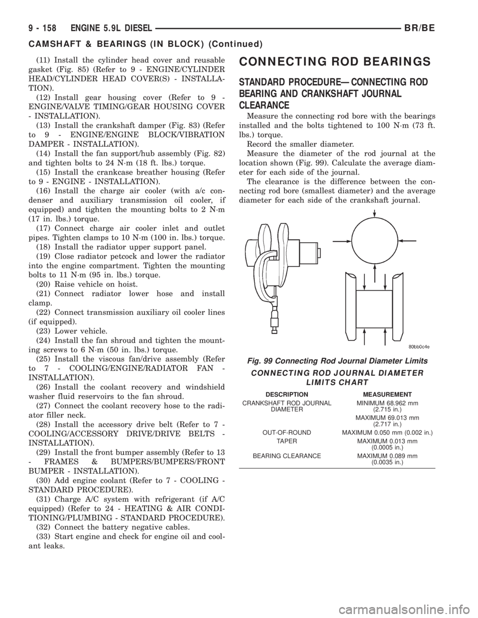
Measure the diameter of the rod journal at the
location shown (Fig. 99). Calculate the average diam-
eter for each side of the journal.
The clearance is the difference between the con-
necting rod bore (smallest diameter) and the average
diameter for each side of the crankshaft journal.
Fig. 99 Connecting Rod Journal Diameter Limits
CONNECTING ROD JOURNAL DIAMETER
LIMITS CHART
DESCRIPTION MEASUREMENT
CRANKSHAFT ROD JOURNAL
DIAMETERMINIMUM 68.962 mm
(2.715 in.)
MAXIMUM 69.013 mm
(2.717 in.)
OUT-OF-ROUND MAXIMUM 0.050 mm (0.002 in.)
TAPER MAXIMUM 0.013 mm
(0.0005 in.)
BEARING CLEARANCE MAXIMUM 0.089 mm
(0.0035 in.)
9 - 158 ENGINE 5.9L DIESELBR/BE
CAMSHAFT & BEARINGS (IN BLOCK) (Continued)
Page 1235 of 2255
CRANKSHAFT MAIN JOURNAL DIAMETER
CHART
ITEM SPECIFICATION
MINIMUM DIAMETER 82.962 mm (3.2662 in.)
MAXIMUM DIAMETER 83.013 mm (3.2682 in.)
Calculate the main bearing journal to bearing
clearance. the clearance specifications are 0.119 mm
(0.00475 inch). If the crankshaft journal is within
limits, replace the main bearings. If not within spec-
ifications, grind the crankshaft to next size and use
oversize bearings.
CRANKSHAFT OIL SEAL -
FRONT
REMOVAL
(1) Disconnect both battery negative cables.
(2) Raise vehicle on hoist.
(3) Partially drain engine coolant into container
suitable for re-use (Refer to 7 - COOLING - STAN-
DARD PROCEDURE).
(4) Lower vehicle.
(5) Remove radiator upper hose.
(6) Disconnect coolant recovery bottle from radia-
tor filler neck and lift bottle off of fan shroud.
(7) Disconnect windshield washer pump supply
hose and electrical connections and lift washer bottle
off of fan shroud.
(8) Remove the fan shroud-to-radiator mounting
bolts.
(9) Remove viscous fan/drive assembly.The fan
drive nut has left handed threads.(Refer to 7 -
COOLING/ENGINE/RADIATOR FAN - REMOVAL).
(10) Remove cooling fan shroud and fan assembly
from the vehicle.
(11) Remove the accessory drive belt (Refer to 7 -
COOLING/ACCESSORY DRIVE/DRIVE BELTS -
REMOVAL).
(12) Remove the cooling fan support/hub from the
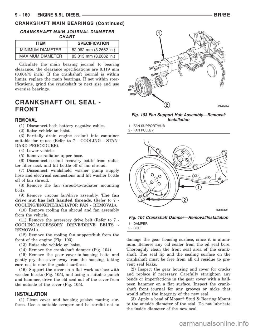
front of the engine (Fig. 103).
(13) Raise the vehicle on hoist.
(14) Remove the crankshaft damper (Fig. 104).
(15) Remove the gear cover-to-housing bolts and
gently pry the cover away from the housing, taking
care not to mar the gasket surfaces.
(16) Support the cover on a flat work surface with
wooden blocks (Fig. 105), and using a suitable punch
and hammer, drive the old seal out of the cover from
the outside of the cover (Fig. 105).
INSTALLATION
(1) Clean cover and housing gasket mating sur-
faces. Use a suitable scraper and be careful not todamage the gear housing surface, since it is alumi-
num. Remove any old sealer from the oil seal bore.
Thoroughly clean the front seal area of the crank-
shaft. The seal lip and the sealing surface on the
crankshaft must be free from all oil residue to pre-
vent seal leaks.
(2) Inspect the gear housing and cover for cracks
and replace if necessary. Carefully straighten any
bends or imperfections in the gear cover with a ball-
peen hammer on a flat surface. Inspect the crank-
shaft front journal for any grooves or nicks that
would affect the integrity of the new seal.
(3) Apply a bead of MopartStud & Bearing Mount
to the outside diameter of the seal. Do not lubricate
the inside diameter of the new seal.
Fig. 103 Fan Support Hub AssemblyÐRemoval/
Installation
1 - FAN SUPPORT/HUB
2 - FAN PULLEY
Fig. 104 Crankshaft DamperÐRemoval/Installation
1 - DAMPER
2 - BOLT
9 - 160 ENGINE 5.9L DIESELBR/BE
CRANKSHAFT MAIN BEARINGS (Continued)
Page 1236 of 2255
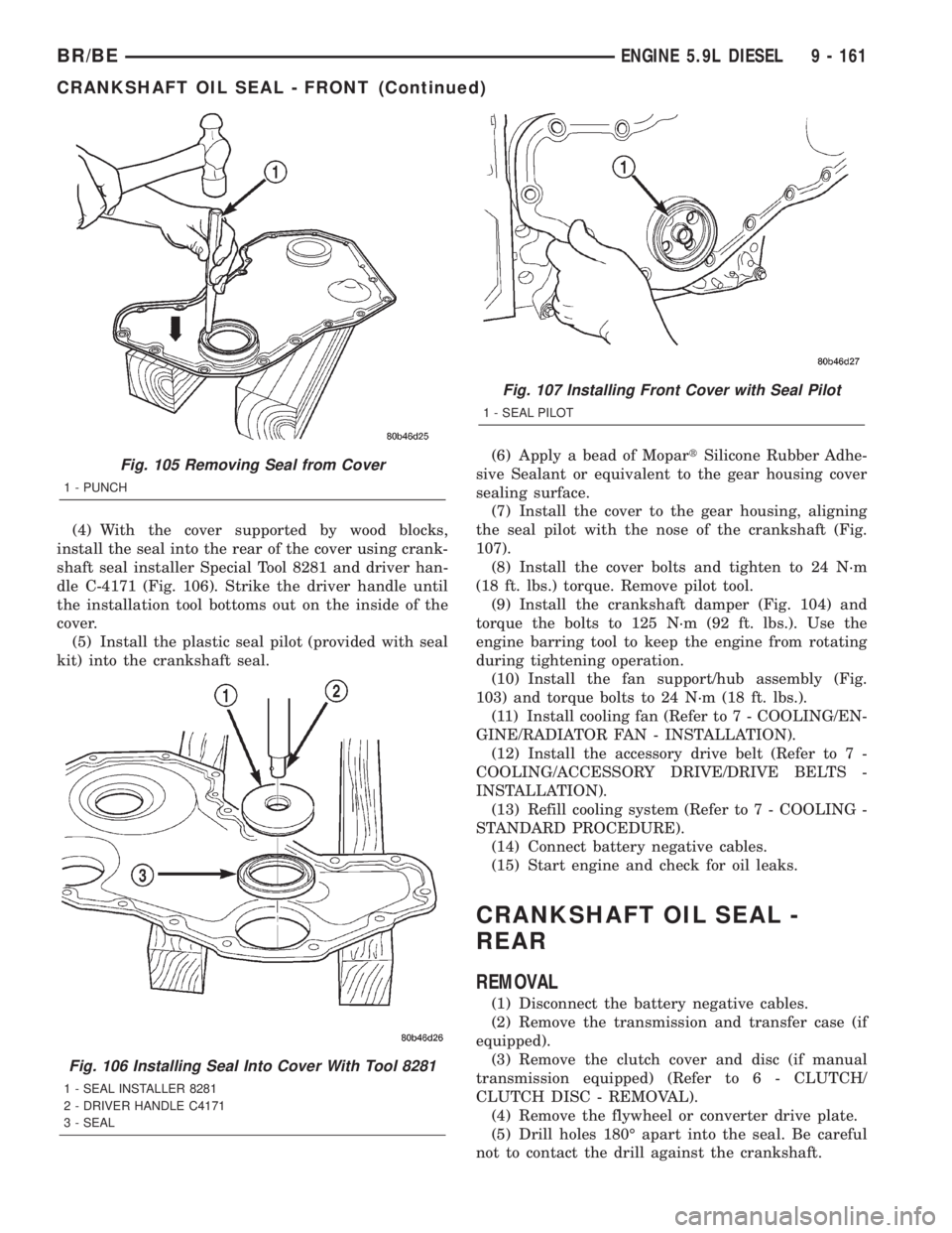
(4) With the cover supported by wood blocks,
install the seal into the rear of the cover using crank-
shaft seal installer Special Tool 8281 and driver han-
dle C-4171 (Fig. 106). Strike the driver handle until
the installation tool bottoms out on the inside of the
cover.
(5) Install the plastic seal pilot (provided with seal
kit) into the crankshaft seal.(6) Apply a bead of MopartSilicone Rubber Adhe-
sive Sealant or equivalent to the gear housing cover
sealing surface.
(7) Install the cover to the gear housing, aligning
the seal pilot with the nose of the crankshaft (Fig.
107).
(8) Install the cover bolts and tighten to 24 N´m
(18 ft. lbs.) torque. Remove pilot tool.
(9) Install the crankshaft damper (Fig. 104) and
torque the bolts to 125 N´m (92 ft. lbs.). Use the
engine barring tool to keep the engine from rotating
during tightening operation.
(10) Install the fan support/hub assembly (Fig.
103) and torque bolts to 24 N´m (18 ft. lbs.).
(11) Install cooling fan (Refer to 7 - COOLING/EN-
GINE/RADIATOR FAN - INSTALLATION).
(12) Install the accessory drive belt (Refer to 7 -
COOLING/ACCESSORY DRIVE/DRIVE BELTS -
INSTALLATION).
(13) Refill cooling system (Refer to 7 - COOLING -
STANDARD PROCEDURE).
(14) Connect battery negative cables.
(15) Start engine and check for oil leaks.
CRANKSHAFT OIL SEAL -
REAR
REMOVAL
(1) Disconnect the battery negative cables.
(2) Remove the transmission and transfer case (if
equipped).
(3) Remove the clutch cover and disc (if manual
transmission equipped) (Refer to 6 - CLUTCH/
CLUTCH DISC - REMOVAL).
(4) Remove the flywheel or converter drive plate.
(5) Drill holes 180É apart into the seal. Be careful
not to contact the drill against the crankshaft.
Fig. 105 Removing Seal from Cover
1 - PUNCH
Fig. 106 Installing Seal Into Cover With Tool 8281
1 - SEAL INSTALLER 8281
2 - DRIVER HANDLE C4171
3 - SEAL
Fig. 107 Installing Front Cover with Seal Pilot
1 - SEAL PILOT
BR/BEENGINE 5.9L DIESEL 9 - 161
CRANKSHAFT OIL SEAL - FRONT (Continued)
Page 1241 of 2255
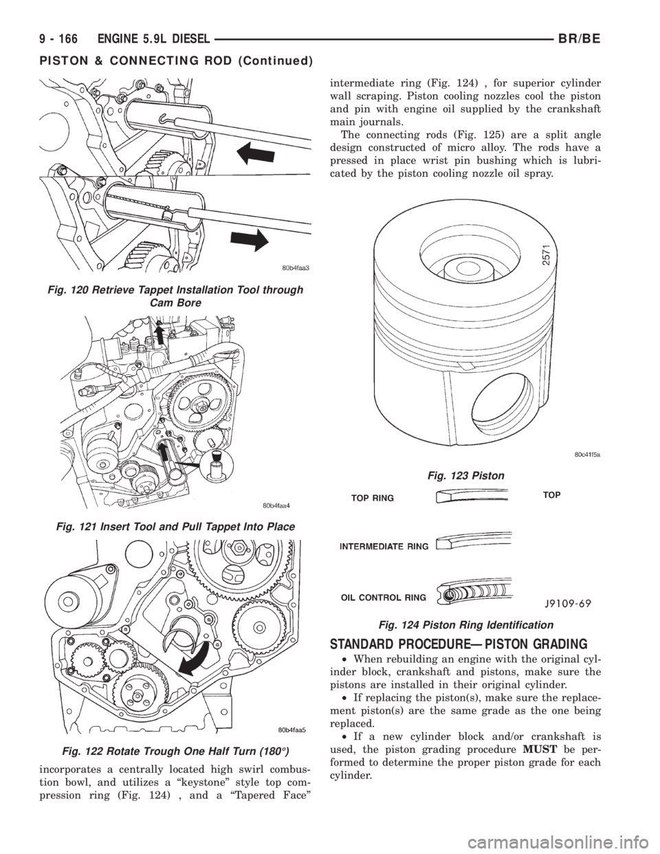
incorporates a centrally located high swirl combus-
tion bowl, and utilizes a ªkeystoneº style top com-
pression ring (Fig. 124) , and a ªTapered Faceºintermediate ring (Fig. 124) , for superior cylinder
wall scraping. Piston cooling nozzles cool the piston
and pin with engine oil supplied by the crankshaft
main journals.
The connecting rods (Fig. 125) are a split angle
design constructed of micro alloy. The rods have a
pressed in place wrist pin bushing which is lubri-
cated by the piston cooling nozzle oil spray.
STANDARD PROCEDUREÐPISTON GRADING
²When rebuilding an engine with the original cyl-
inder block, crankshaft and pistons, make sure the
pistons are installed in their original cylinder.
²If replacing the piston(s), make sure the replace-
ment piston(s) are the same grade as the one being
replaced.
²If a new cylinder block and/or crankshaft is
used, the piston grading procedureMUSTbe per-
formed to determine the proper piston grade for each
cylinder.
Fig. 120 Retrieve Tappet Installation Tool through
Cam Bore
Fig. 121 Insert Tool and Pull Tappet Into Place
Fig. 122 Rotate Trough One Half Turn (180É)
Fig. 123 Piston
Fig. 124 Piston Ring Identification
9 - 166 ENGINE 5.9L DIESELBR/BE
PISTON & CONNECTING ROD (Continued)
Page 1247 of 2255
PISTON RING GAP CHART
TOP RING 0.35 - 0.45 mm (0.014 - 0.0177
in.)
INTERMEDIATE
RING0.85-1.15 mm (0.0334 -
0.0452 in.)
OIL CONTROL
RING0.250-0.550
mm(0.0100 -
0.0215 in.)
(4) The top surface of all of the rings are identified
with the word TOP or the supplier's MARK. Assem-
ble the rings with the word TOP or the supplier's
MARK up.
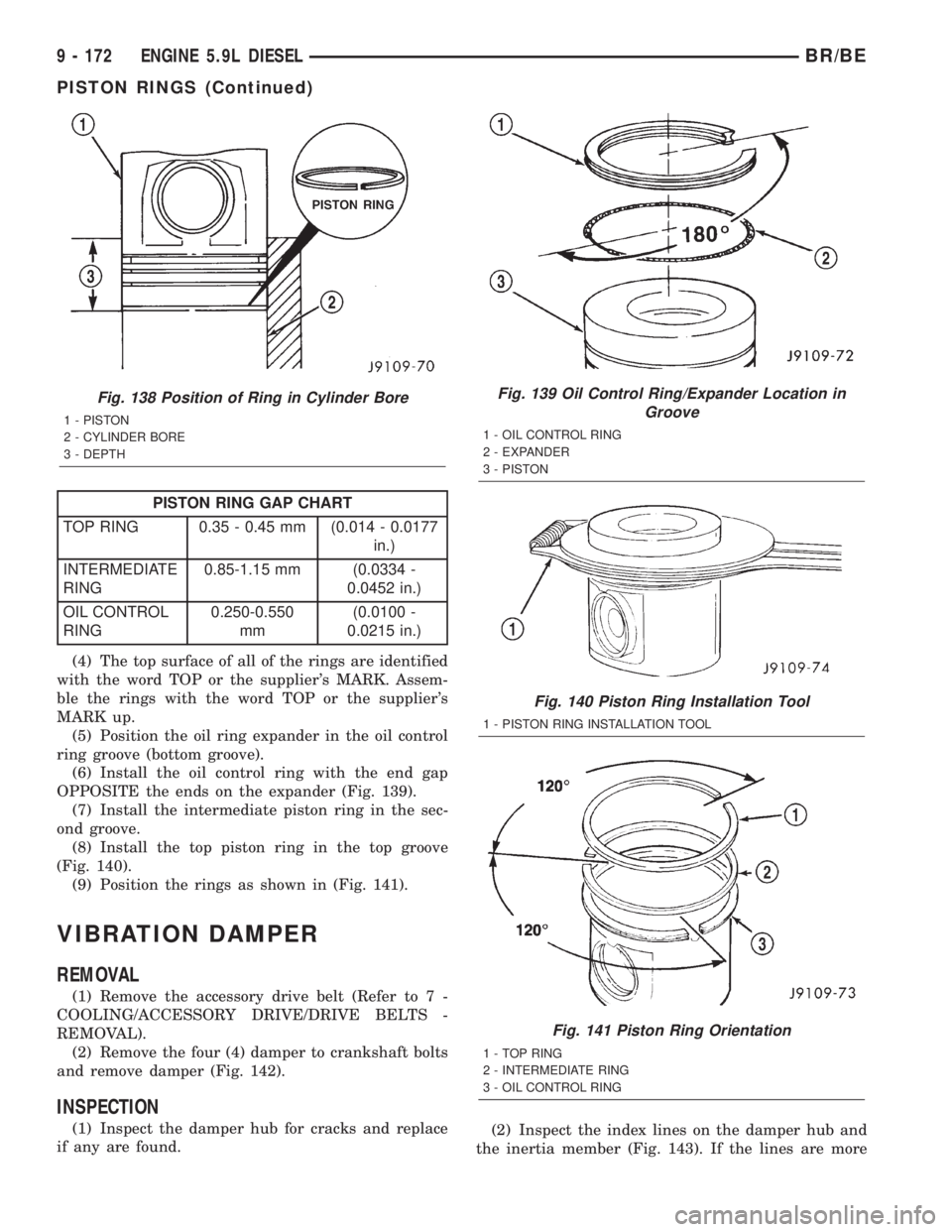
(5) Position the oil ring expander in the oil control
ring groove (bottom groove).
(6) Install the oil control ring with the end gap
OPPOSITE the ends on the expander (Fig. 139).
(7) Install the intermediate piston ring in the sec-
ond groove.
(8) Install the top piston ring in the top groove
(Fig. 140).
(9) Position the rings as shown in (Fig. 141).
VIBRATION DAMPER
REMOVAL
(1) Remove the accessory drive belt (Refer to 7 -
COOLING/ACCESSORY DRIVE/DRIVE BELTS -
REMOVAL).
(2) Remove the four (4) damper to crankshaft bolts
and remove damper (Fig. 142).
INSPECTION
(1) Inspect the damper hub for cracks and replace
if any are found.(2) Inspect the index lines on the damper hub and
the inertia member (Fig. 143). If the lines are more
Fig. 138 Position of Ring in Cylinder Bore
1 - PISTON
2 - CYLINDER BORE
3 - DEPTH
Fig. 139 Oil Control Ring/Expander Location in
Groove
1 - OIL CONTROL RING
2 - EXPANDER
3 - PISTON
Fig. 140 Piston Ring Installation Tool
1 - PISTON RING INSTALLATION TOOL
Fig. 141 Piston Ring Orientation
1 - TOP RING
2 - INTERMEDIATE RING
3 - OIL CONTROL RING
9 - 172 ENGINE 5.9L DIESELBR/BE
PISTON RINGS (Continued)