2002 DODGE RAM cooling
[x] Cancel search: coolingPage 2126 of 2255
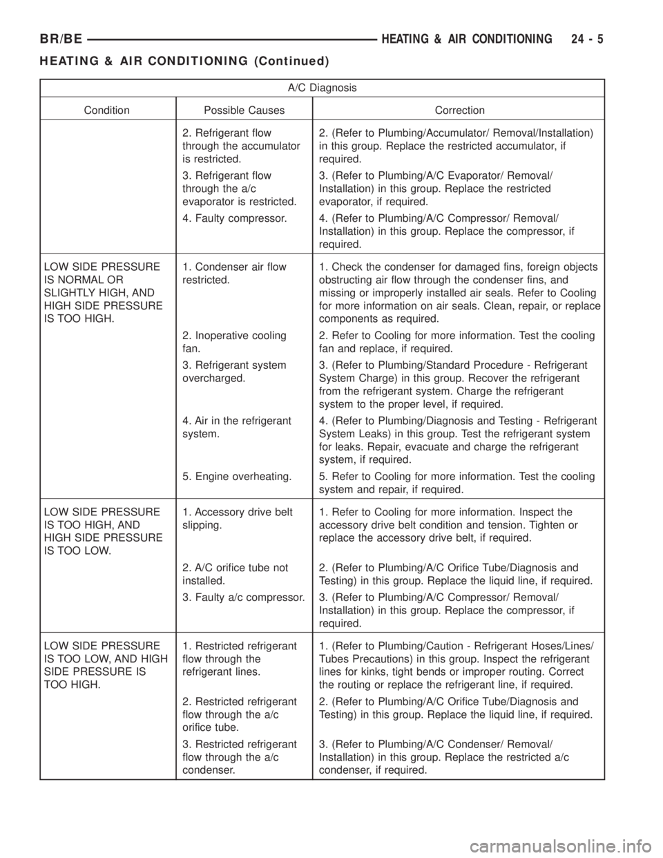
A/C Diagnosis
Condition Possible Causes Correction
2. Refrigerant flow
through the accumulator
is restricted.2. (Refer to Plumbing/Accumulator/ Removal/Installation)
in this group. Replace the restricted accumulator, if
required.
3. Refrigerant flow
through the a/c
evaporator is restricted.3. (Refer to Plumbing/A/C Evaporator/ Removal/
Installation) in this group. Replace the restricted
evaporator, if required.
4. Faulty compressor. 4. (Refer to Plumbing/A/C Compressor/ Removal/
Installation) in this group. Replace the compressor, if
required.
LOW SIDE PRESSURE
IS NORMAL OR
SLIGHTLY HIGH, AND
HIGH SIDE PRESSURE
IS TOO HIGH.1. Condenser air flow
restricted.1. Check the condenser for damaged fins, foreign objects
obstructing air flow through the condenser fins, and
missing or improperly installed air seals. Refer to Cooling
for more information on air seals. Clean, repair, or replace
components as required.
2. Inoperative cooling
fan.2. Refer to Cooling for more information. Test the cooling
fan and replace, if required.
3. Refrigerant system
overcharged.3. (Refer to Plumbing/Standard Procedure - Refrigerant
System Charge) in this group. Recover the refrigerant
from the refrigerant system. Charge the refrigerant
system to the proper level, if required.
4. Air in the refrigerant
system.4. (Refer to Plumbing/Diagnosis and Testing - Refrigerant
System Leaks) in this group. Test the refrigerant system
for leaks. Repair, evacuate and charge the refrigerant
system, if required.
5. Engine overheating. 5. Refer to Cooling for more information. Test the cooling
system and repair, if required.
LOW SIDE PRESSURE
IS TOO HIGH, AND
HIGH SIDE PRESSURE
IS TOO LOW.1. Accessory drive belt
slipping.1. Refer to Cooling for more information. Inspect the
accessory drive belt condition and tension. Tighten or
replace the accessory drive belt, if required.
2. A/C orifice tube not
installed.2. (Refer to Plumbing/A/C Orifice Tube/Diagnosis and
Testing) in this group. Replace the liquid line, if required.
3. Faulty a/c compressor. 3. (Refer to Plumbing/A/C Compressor/ Removal/
Installation) in this group. Replace the compressor, if
required.
LOW SIDE PRESSURE
IS TOO LOW, AND HIGH
SIDE PRESSURE IS
TOO HIGH.1. Restricted refrigerant
flow through the
refrigerant lines.1. (Refer to Plumbing/Caution - Refrigerant Hoses/Lines/
Tubes Precautions) in this group. Inspect the refrigerant
lines for kinks, tight bends or improper routing. Correct
the routing or replace the refrigerant line, if required.
2. Restricted refrigerant
flow through the a/c
orifice tube.2. (Refer to Plumbing/A/C Orifice Tube/Diagnosis and
Testing) in this group. Replace the liquid line, if required.
3. Restricted refrigerant
flow through the a/c
condenser.3. (Refer to Plumbing/A/C Condenser/ Removal/
Installation) in this group. Replace the restricted a/c
condenser, if required.
BR/BEHEATING & AIR CONDITIONING 24 - 5
HEATING & AIR CONDITIONING (Continued)
Page 2127 of 2255
DIAGNOSIS AND TESTING - HEATER
PERFORMANCE
Before performing the following tests, refer to Cool-
ing for the procedures to check the engine coolant
level and flow, engine coolant reserve/recovery sys-
tem operation, accessory drive belt condition and ten-
sion, radiator air flow and the fan drive operation.
Also be certain that the accessory vacuum supply
line is connected at the engine vacuum source.
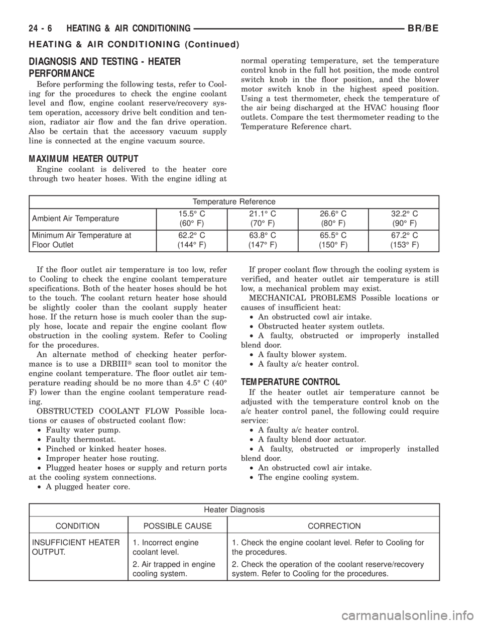
MAXIMUM HEATER OUTPUT
Engine coolant is delivered to the heater core
through two heater hoses. With the engine idling atnormal operating temperature, set the temperature
control knob in the full hot position, the mode control
switch knob in the floor position, and the blower
motor switch knob in the highest speed position.
Using a test thermometer, check the temperature of
the air being discharged at the HVAC housing floor
outlets. Compare the test thermometer reading to the
Temperature Reference chart.
Temperature Reference
Ambient Air Temperature15.5É C
(60É F)21.1É C
(70É F)26.6É C
(80É F)32.2É C
(90É F)
Minimum Air Temperature at
Floor Outlet62.2É C
(144É F)63.8É C
(147É F)65.5É C
(150É F)67.2É C
(153É F)
If the floor outlet air temperature is too low, refer
to Cooling to check the engine coolant temperature
specifications. Both of the heater hoses should be hot
to the touch. The coolant return heater hose should
be slightly cooler than the coolant supply heater
hose. If the return hose is much cooler than the sup-
ply hose, locate and repair the engine coolant flow
obstruction in the cooling system. Refer to Cooling
for the procedures.
An alternate method of checking heater perfor-
mance is to use a DRBIIItscan tool to monitor the
engine coolant temperature. The floor outlet air tem-
perature reading should be no more than 4.5É C (40É
F) lower than the engine coolant temperature read-
ing.
OBSTRUCTED COOLANT FLOW Possible loca-
tions or causes of obstructed coolant flow:
²Faulty water pump.
²Faulty thermostat.
²Pinched or kinked heater hoses.
²Improper heater hose routing.
²Plugged heater hoses or supply and return ports
at the cooling system connections.
²A plugged heater core.If proper coolant flow through the cooling system is
verified, and heater outlet air temperature is still
low, a mechanical problem may exist.
MECHANICAL PROBLEMS Possible locations or
causes of insufficient heat:
²An obstructed cowl air intake.
²Obstructed heater system outlets.
²A faulty, obstructed or improperly installed
blend door.
²A faulty blower system.
²A faulty a/c heater control.
TEMPERATURE CONTROL
If the heater outlet air temperature cannot be
adjusted with the temperature control knob on the
a/c heater control panel, the following could require
service:
²A faulty a/c heater control.
²A faulty blend door actuator.
²A faulty, obstructed or improperly installed
blend door.
²An obstructed cowl air intake.
²The engine cooling system.
Heater Diagnosis
CONDITION POSSIBLE CAUSE CORRECTION
INSUFFICIENT HEATER
OUTPUT.1. Incorrect engine
coolant level.1. Check the engine coolant level. Refer to Cooling for
the procedures.
2. Air trapped in engine
cooling system.2. Check the operation of the coolant reserve/recovery
system. Refer to Cooling for the procedures.
24 - 6 HEATING & AIR CONDITIONINGBR/BE
HEATING & AIR CONDITIONING (Continued)
Page 2128 of 2255
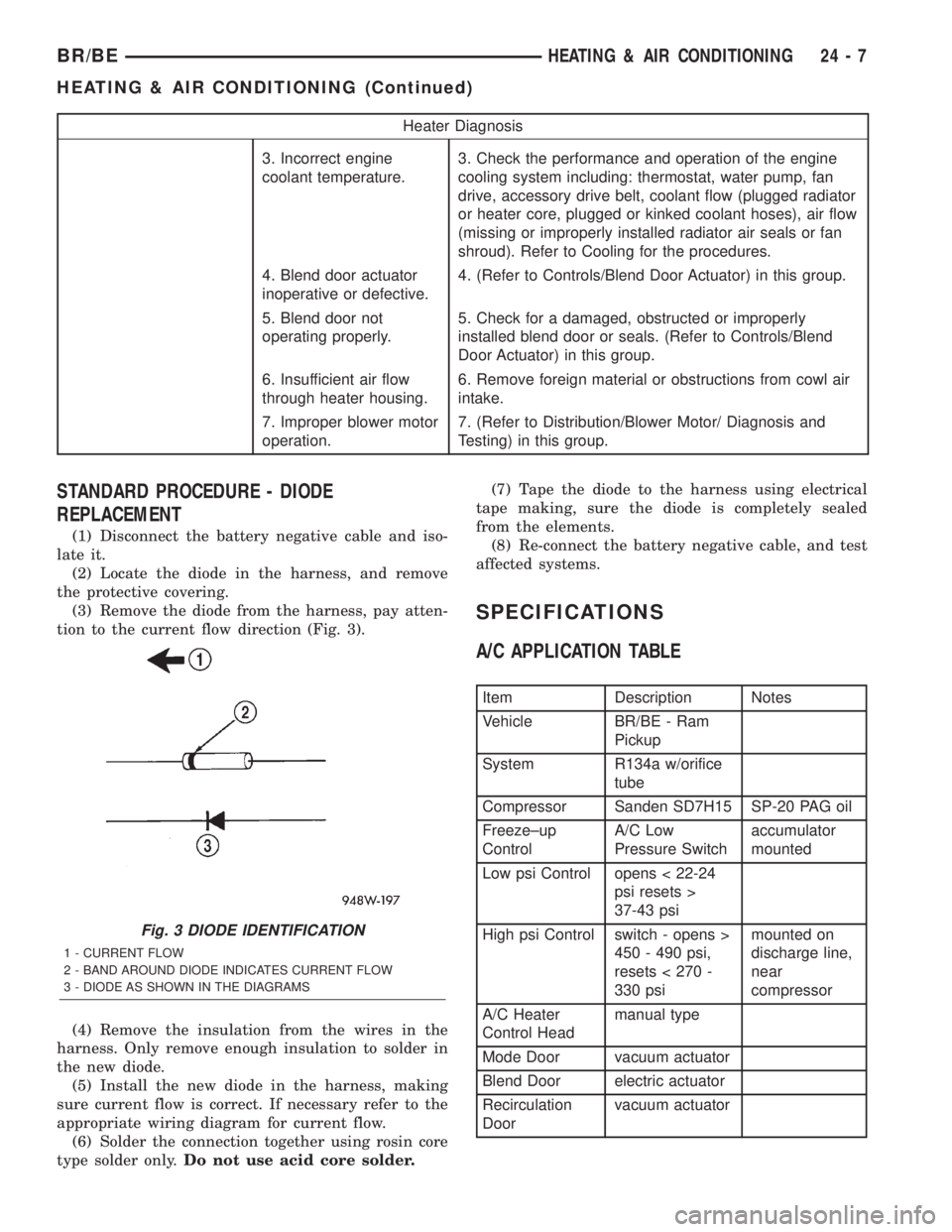
Heater Diagnosis
3. Incorrect engine
coolant temperature.3. Check the performance and operation of the engine
cooling system including: thermostat, water pump, fan
drive, accessory drive belt, coolant flow (plugged radiator
or heater core, plugged or kinked coolant hoses), air flow
(missing or improperly installed radiator air seals or fan
shroud). Refer to Cooling for the procedures.
4. Blend door actuator
inoperative or defective.4. (Refer to Controls/Blend Door Actuator) in this group.
5. Blend door not
operating properly.5. Check for a damaged, obstructed or improperly
installed blend door or seals. (Refer to Controls/Blend
Door Actuator) in this group.
6. Insufficient air flow
through heater housing.6. Remove foreign material or obstructions from cowl air
intake.
7. Improper blower motor
operation.7. (Refer to Distribution/Blower Motor/ Diagnosis and
Testing) in this group.
STANDARD PROCEDURE - DIODE
REPLACEMENT
(1) Disconnect the battery negative cable and iso-
late it.
(2) Locate the diode in the harness, and remove
the protective covering.
(3) Remove the diode from the harness, pay atten-
tion to the current flow direction (Fig. 3).
(4) Remove the insulation from the wires in the
harness. Only remove enough insulation to solder in
the new diode.
(5) Install the new diode in the harness, making
sure current flow is correct. If necessary refer to the
appropriate wiring diagram for current flow.
(6) Solder the connection together using rosin core
type solder only.Do not use acid core solder.(7) Tape the diode to the harness using electrical
tape making, sure the diode is completely sealed
from the elements.
(8) Re-connect the battery negative cable, and test
affected systems.
SPECIFICATIONS
A/C APPLICATION TABLE
Item Description Notes
Vehicle BR/BE - Ram
Pickup
System R134a w/orifice
tube
Compressor Sanden SD7H15 SP-20 PAG oil
Freeze±up
ControlA/C Low
Pressure Switchaccumulator
mounted
Low psi Control opens < 22-24
psi resets >
37-43 psi
High psi Control switch - opens >
450 - 490 psi,
resets < 270 -
330 psimounted on
discharge line,
near
compressor
A/C Heater
Control Headmanual type
Mode Door vacuum actuator
Blend Door electric actuator
Recirculation
Doorvacuum actuator
Fig. 3 DIODE IDENTIFICATION
1 - CURRENT FLOW
2 - BAND AROUND DIODE INDICATES CURRENT FLOW
3 - DIODE AS SHOWN IN THE DIAGRAMS
BR/BEHEATING & AIR CONDITIONING 24 - 7
HEATING & AIR CONDITIONING (Continued)
Page 2129 of 2255
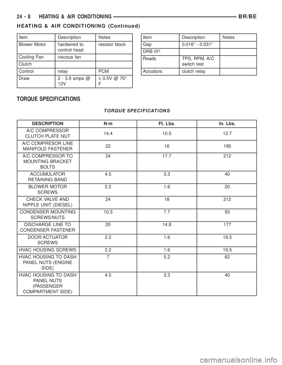
Item Description Notes
Blower Motor hardwired to
control headresistor block
Cooling Fan viscous fan
Clutch
Control relay PCM
Draw 2 - 3.9 amps @
12V 0.5V @ 70É
FItem Description Notes
Gap 0.0169- 0.0319
DRB IIIT
Reads TPS, RPM, A/C
switch test
Actuators clutch relay
TORQUE SPECIFICATIONS
TORQUE SPECIFICATIONS
DESCRIPTION N´m Ft. Lbs. In. Lbs.
A/C COMPRESSOR
CLUTCH PLATE NUT14.4 10.5 12.7
A/C COMPRESOR LINE
MANIFOLD FASTENER22 16 195
A/C COMPRESSOR TO
MOUNTING BRACKET
BOLTS24 17.7 212
ACCUMULATOR
RETAINING BAND4.5 3.3 40
BLOWER MOTOR
SCREWS2.2 1.6 20
CHECK VALVE AND
NIPPLE UNIT (DIESEL)24 18 212
CONDENSER MOUNTING
SCREWS/NUTS10.5 7.7 93
DISCHARGE LINE TO
CONDENSER FASTENER20 14.8 177
DOOR ACTUATOR
SCREWS2.2 1.6 19.5
HVAC HOUSING SCREWS 2.2 1.6 19.5
HVAC HOUSING TO DASH
PANEL NUTS (ENGINE
SIDE)7 5.2 62
HVAC HOUSING TO DASH
PANEL NUTS
(PASSENGER
COMPARTMENT SIDE)4.5 3.3 40
24 - 8 HEATING & AIR CONDITIONINGBR/BE
HEATING & AIR CONDITIONING (Continued)
Page 2139 of 2255
(1) The relay common feed terminal cavity (30) is
connected to fused battery feed. There should be bat-
tery voltage at the cavity for relay terminal 30 at all
times. If OK, go to Step 2. If not OK, repair the open
circuit to the fuse in the PDC as required.
(2) The relay normally closed terminal (87A) is not
used in this application. Go to Step 3.
(3) The relay normally open terminal cavity (87) is
connected to the compressor clutch coil. There should
be continuity between this cavity and the A/C com-
pressor clutch relay output circuit cavity of the com-
pressor clutch coil wire harness connector. If OK, go
to Step 4. If not OK, repair the open circuit as
required.
(4) The relay coil battery terminal (86) is con-
nected to the fused ignition switch output (run/start)
circuit. There should be battery voltage at the cavity
for relay terminal 86 with the ignition switch in the
On position. If OK, go to Step 5. If not OK, repair the
open circuit to the fuse in the junction block as
required.
(5) The coil ground terminal cavity (85) is switched
to ground through the Powertrain Control Module
(PCM). There should be continuity between this cav-
ity and the A/C compressor clutch relay control cir-
cuit cavity of the PCM wire harness connector C
(gray) at all times. If not OK, repair the open circuit
as required.
REMOVAL
(1) Disconnect and isolate the battery negative
cable.
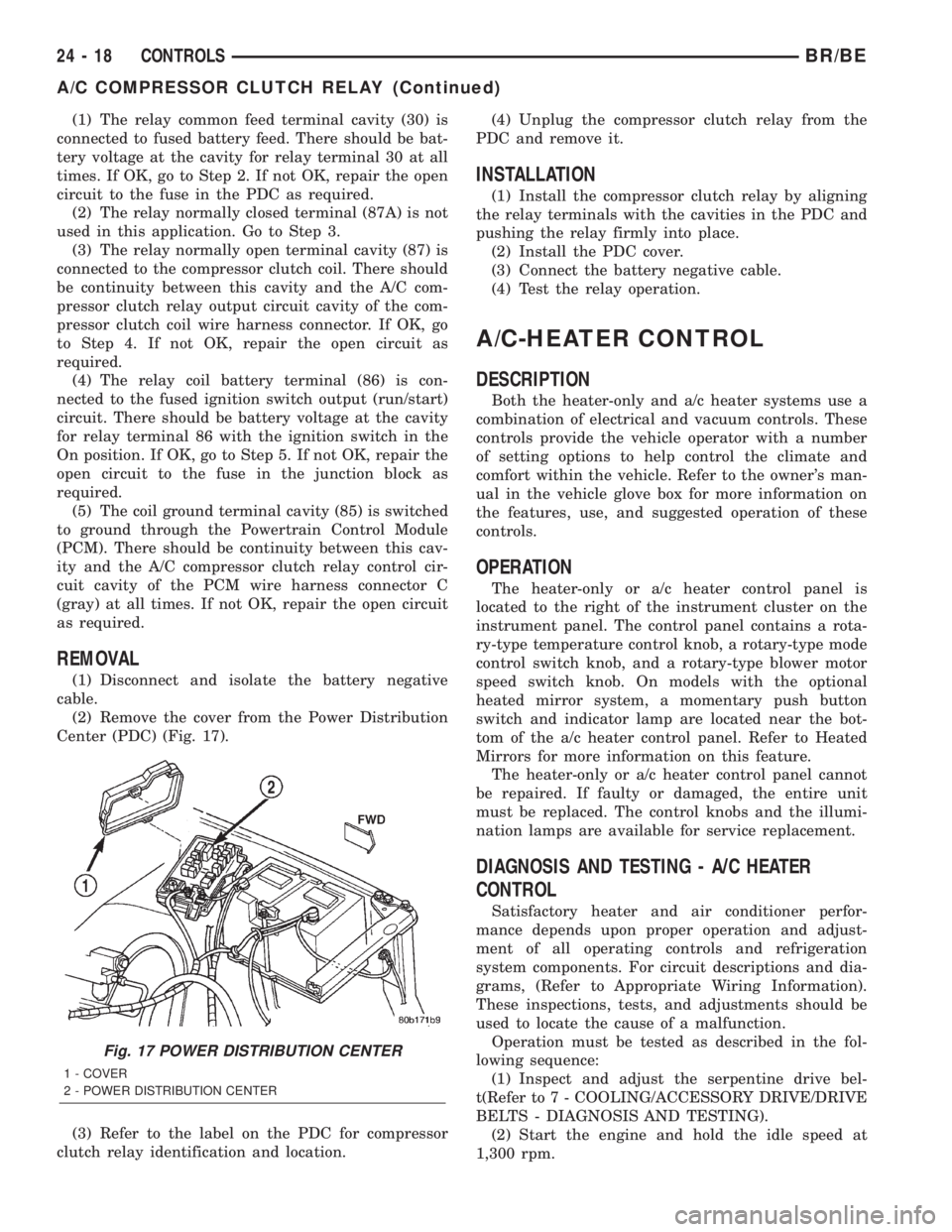
(2) Remove the cover from the Power Distribution
Center (PDC) (Fig. 17).
(3) Refer to the label on the PDC for compressor
clutch relay identification and location.(4) Unplug the compressor clutch relay from the
PDC and remove it.
INSTALLATION
(1) Install the compressor clutch relay by aligning
the relay terminals with the cavities in the PDC and
pushing the relay firmly into place.
(2) Install the PDC cover.
(3) Connect the battery negative cable.
(4) Test the relay operation.
A/C-HEATER CONTROL
DESCRIPTION
Both the heater-only and a/c heater systems use a
combination of electrical and vacuum controls. These
controls provide the vehicle operator with a number
of setting options to help control the climate and
comfort within the vehicle. Refer to the owner's man-
ual in the vehicle glove box for more information on
the features, use, and suggested operation of these
controls.
OPERATION
The heater-only or a/c heater control panel is
located to the right of the instrument cluster on the
instrument panel. The control panel contains a rota-
ry-type temperature control knob, a rotary-type mode
control switch knob, and a rotary-type blower motor
speed switch knob. On models with the optional
heated mirror system, a momentary push button
switch and indicator lamp are located near the bot-
tom of the a/c heater control panel. Refer to Heated
Mirrors for more information on this feature.
The heater-only or a/c heater control panel cannot
be repaired. If faulty or damaged, the entire unit
must be replaced. The control knobs and the illumi-
nation lamps are available for service replacement.
DIAGNOSIS AND TESTING - A/C HEATER
CONTROL
Satisfactory heater and air conditioner perfor-
mance depends upon proper operation and adjust-
ment of all operating controls and refrigeration
system components. For circuit descriptions and dia-
grams, (Refer to Appropriate Wiring Information).
These inspections, tests, and adjustments should be
used to locate the cause of a malfunction.
Operation must be tested as described in the fol-
lowing sequence:
(1) Inspect and adjust the serpentine drive bel-
t(Refer to 7 - COOLING/ACCESSORY DRIVE/DRIVE
BELTS - DIAGNOSIS AND TESTING).
(2) Start the engine and hold the idle speed at
1,300 rpm.
Fig. 17 POWER DISTRIBUTION CENTER
1 - COVER
2 - POWER DISTRIBUTION CENTER
24 - 18 CONTROLSBR/BE
A/C COMPRESSOR CLUTCH RELAY (Continued)
Page 2153 of 2255
DIAGNOSIS AND TESTING - BLOWER MOTOR
WARNING: ON VEHICLES EQUIPPED WITH AIR-
BAGS, DISABLE THE AIRBAG SYSTEM BEFORE
ATTEMPTING ANY STEERING WHEEL, STEERING
COLUMN, OR INSTRUMENT PANEL COMPONENT
DIAGNOSIS OR SERVICE. DISCONNECT AND ISO-
LATE THE BATTERY NEGATIVE (GROUND) CABLE,
THEN WAIT TWO MINUTES FOR THE AIRBAG SYS-
TEM CAPACITOR TO DISCHARGE BEFORE PER-
FORMING FURTHER DIAGNOSIS OR SERVICE. THIS
IS THE ONLY SURE WAY TO DISABLE THE AIRBAG
SYSTEM. FAILURE TO TAKE THE PROPER PRE-
CAUTIONS COULD RESULT IN AN ACCIDENTAL
AIRBAG DEPLOYMENT AND POSSIBLE PERSONAL
INJURY.
For circuit descriptions and diagrams, (Refer to
Appropriate Wiring Information). Possible causes of
an inoperative blower motor include:
²Faulty fuse
²Faulty blower motor circuit wiring or wire har-
ness connectors
²Faulty blower motor resistor
²Faulty blower motor relay
²Faulty blower motor switch
²Faulty a/c heater mode control switch
²Faulty blower motor.
Possible causes of the blower motor not operating
in all speeds include:
²Faulty fuse
²Faulty blower motor switch
²Faulty blower motor resistor
²Faulty blower motor relay
²Faulty blower motor circuit wiring or wire har-
ness connectors.
VIBRATION
Possible causes of blower motor vibration include:
²Improper blower motor mounting
²Improper blower wheel mounting
²Blower wheel out of balance or deformed
²Blower motor faulty.
NOISE
To verify that the blower is the source of the noise,
unplug the blower motor wire harness connector and
operate the HVAC system. If the noise goes away,
possible causes include:
²Foreign material in the HVAC housing
²Improper blower motor mounting
²Improper blower wheel mounting
²Blower motor faulty.
REMOVAL
(1) Disconnect and isolate the battery negative
cable.
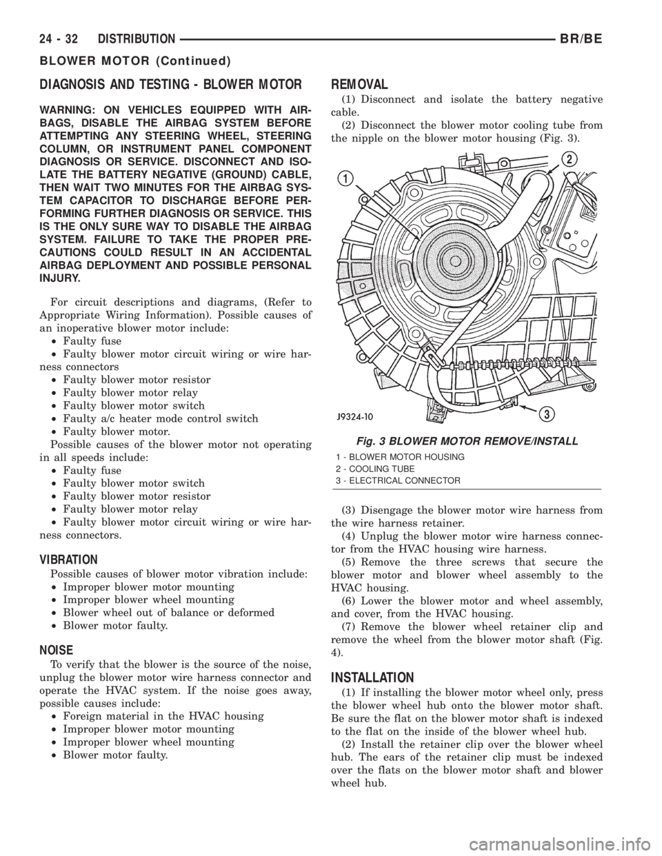
(2) Disconnect the blower motor cooling tube from
the nipple on the blower motor housing (Fig. 3).
(3) Disengage the blower motor wire harness from
the wire harness retainer.
(4) Unplug the blower motor wire harness connec-
tor from the HVAC housing wire harness.
(5) Remove the three screws that secure the
blower motor and blower wheel assembly to the
HVAC housing.
(6) Lower the blower motor and wheel assembly,
and cover, from the HVAC housing.
(7) Remove the blower wheel retainer clip and
remove the wheel from the blower motor shaft (Fig.
4).
INSTALLATION
(1) If installing the blower motor wheel only, press
the blower wheel hub onto the blower motor shaft.
Be sure the flat on the blower motor shaft is indexed
to the flat on the inside of the blower wheel hub.
(2) Install the retainer clip over the blower wheel
hub. The ears of the retainer clip must be indexed
over the flats on the blower motor shaft and blower
wheel hub.
Fig. 3 BLOWER MOTOR REMOVE/INSTALL
1 - BLOWER MOTOR HOUSING
2 - COOLING TUBE
3 - ELECTRICAL CONNECTOR
24 - 32 DISTRIBUTIONBR/BE
BLOWER MOTOR (Continued)
Page 2154 of 2255
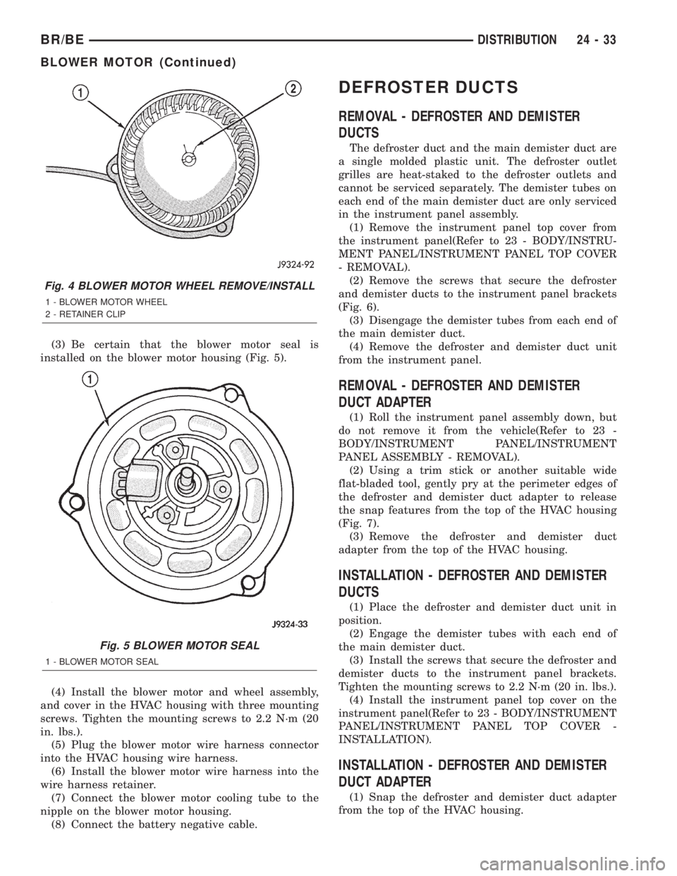
(3) Be certain that the blower motor seal is
installed on the blower motor housing (Fig. 5).
(4) Install the blower motor and wheel assembly,
and cover in the HVAC housing with three mounting
screws. Tighten the mounting screws to 2.2 N´m (20
in. lbs.).
(5) Plug the blower motor wire harness connector
into the HVAC housing wire harness.
(6) Install the blower motor wire harness into the
wire harness retainer.
(7) Connect the blower motor cooling tube to the
nipple on the blower motor housing.
(8) Connect the battery negative cable.
DEFROSTER DUCTS
REMOVAL - DEFROSTER AND DEMISTER
DUCTS
The defroster duct and the main demister duct are
a single molded plastic unit. The defroster outlet
grilles are heat-staked to the defroster outlets and
cannot be serviced separately. The demister tubes on
each end of the main demister duct are only serviced
in the instrument panel assembly.
(1) Remove the instrument panel top cover from
the instrument panel(Refer to 23 - BODY/INSTRU-
MENT PANEL/INSTRUMENT PANEL TOP COVER
- REMOVAL).
(2) Remove the screws that secure the defroster
and demister ducts to the instrument panel brackets
(Fig. 6).
(3) Disengage the demister tubes from each end of
the main demister duct.
(4) Remove the defroster and demister duct unit
from the instrument panel.
REMOVAL - DEFROSTER AND DEMISTER
DUCT ADAPTER
(1) Roll the instrument panel assembly down, but
do not remove it from the vehicle(Refer to 23 -
BODY/INSTRUMENT PANEL/INSTRUMENT
PANEL ASSEMBLY - REMOVAL).
(2) Using a trim stick or another suitable wide
flat-bladed tool, gently pry at the perimeter edges of
the defroster and demister duct adapter to release
the snap features from the top of the HVAC housing
(Fig. 7).
(3) Remove the defroster and demister duct
adapter from the top of the HVAC housing.
INSTALLATION - DEFROSTER AND DEMISTER
DUCTS
(1) Place the defroster and demister duct unit in
position.
(2) Engage the demister tubes with each end of
the main demister duct.
(3) Install the screws that secure the defroster and
demister ducts to the instrument panel brackets.
Tighten the mounting screws to 2.2 N´m (20 in. lbs.).
(4) Install the instrument panel top cover on the
instrument panel(Refer to 23 - BODY/INSTRUMENT
PANEL/INSTRUMENT PANEL TOP COVER -
INSTALLATION).
INSTALLATION - DEFROSTER AND DEMISTER
DUCT ADAPTER
(1) Snap the defroster and demister duct adapter
from the top of the HVAC housing.
Fig. 4 BLOWER MOTOR WHEEL REMOVE/INSTALL
1 - BLOWER MOTOR WHEEL
2 - RETAINER CLIP
Fig. 5 BLOWER MOTOR SEAL
1 - BLOWER MOTOR SEAL
BR/BEDISTRIBUTION 24 - 33
BLOWER MOTOR (Continued)
Page 2156 of 2255
(1) Disconnect and isolate the battery negative
cable.
(2) If the vehicle is not equipped with air condi-
tioning, go to Step 6. If the vehicle is equipped with
air conditioning, recover the refrigerant from the sys-
tem. (Refer to 24 - HEATING & AIR CONDITION-
ING/PLUMBING - STANDARD PROCEDURE -
REFRIGERANT RECOVERY)
(3) Remove the instrument panel from the vehicle.
Refer to Instrument Panel System for the procedures.
(4) Disconnect the liquid line refrigerant line fit-
ting from the evaporator inlet tube. (Refer to 24 -
HEATING & AIR CONDITIONING/PLUMBING -
STANDARD PROCEDURE - A/C LINE COUPLERS)
Install plugs in, or tape over all of the opened refrig-
erant line fittings.
(5) Remove the accumulator. (Refer to 24 - HEAT-
ING & AIR CONDITIONING/PLUMBING/ACCU-
MULATOR - REMOVAL) Install plugs in, or tape
over all of the opened refrigerant line fittings.
(6) Drain the engine cooling system(Refer to 7 -
COOLING - STANDARD PROCEDURE) and (Refer
to 7 - COOLING - STANDARD PROCEDURE).
(7) Disconnect the heater hoses from the heater
core tubes. Refer to Cooling for the procedures.
Install plugs in, or tape over the opened heater core
tubes.
(8) Remove the Powertrain Control Module (PCM)
from the dash panel and set it aside, but do not
unplug the PCM wire harness connectors. Refer to
Electronic Control Modules for the procedures.
(9) Remove the nuts from the HVAC housing
mounting studs on the engine compartment side of
the dash panel.
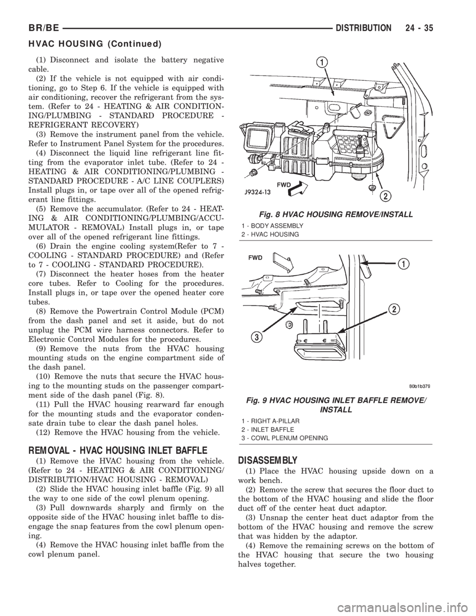
(10) Remove the nuts that secure the HVAC hous-
ing to the mounting studs on the passenger compart-
ment side of the dash panel (Fig. 8).
(11) Pull the HVAC housing rearward far enough
for the mounting studs and the evaporator conden-
sate drain tube to clear the dash panel holes.
(12) Remove the HVAC housing from the vehicle.
REMOVAL - HVAC HOUSING INLET BAFFLE
(1) Remove the HVAC housing from the vehicle.
(Refer to 24 - HEATING & AIR CONDITIONING/
DISTRIBUTION/HVAC HOUSING - REMOVAL)
(2) Slide the HVAC housing inlet baffle (Fig. 9) all
the way to one side of the cowl plenum opening.
(3) Pull downwards sharply and firmly on the
opposite side of the HVAC housing inlet baffle to dis-
engage the snap features from the cowl plenum open-
ing.
(4) Remove the HVAC housing inlet baffle from the
cowl plenum panel.DISASSEMBLY
(1) Place the HVAC housing upside down on a
work bench.
(2) Remove the screw that secures the floor duct to
the bottom of the HVAC housing and slide the floor
duct off of the center heat duct adaptor.
(3) Unsnap the center heat duct adaptor from the
bottom of the HVAC housing and remove the screw
that was hidden by the adaptor.
(4) Remove the remaining screws on the bottom of
the HVAC housing that secure the two housing
halves together.
Fig. 8 HVAC HOUSING REMOVE/INSTALL
1 - BODY ASSEMBLY
2 - HVAC HOUSING
Fig. 9 HVAC HOUSING INLET BAFFLE REMOVE/
INSTALL
1 - RIGHT A-PILLAR
2 - INLET BAFFLE
3 - COWL PLENUM OPENING
BR/BEDISTRIBUTION 24 - 35
HVAC HOUSING (Continued)