2002 DODGE RAM air condition
[x] Cancel search: air conditionPage 636 of 2255
Once the speed control has been disengaged,
depressing the ACCEL switch restores the vehicle to
the target speed that was stored in the PCM's RAM.
NOTE: Depressing the OFF switch will erase the set
speed stored in the PCM's RAM.
If, while the speed control is engaged, the driver
wishes to increase vehicle speed, the PCM is pro-
grammed for an acceleration feature. With the
ACCEL switch held closed, the vehicle accelerates
slowly to the desired speed. The new target speed is
stored in the PCM's RAM when the ACCEL switch is
released. The PCM also has a9tap-up9feature in
which vehicle speed increases at a rate of approxi-
mately 2 mph for each momentary switch activation
of the ACCEL switch.
The PCM also provides a means to decelerate with-
out disengaging speed control. To decelerate from an
existing recorded target speed, depress and hold the
COAST switch until the desired speed is reached.
Then release the switch. The ON, OFF switch oper-
ates two components: the PCM's ON, OFF input, and
the battery voltage to the brake switch, which powers
the speed control servo.
Diesel With Manual Trans.
When speed control is selected by depressing the
ON, OFF switch, the Engine Control Module (ECM)
allows a set speed to be stored in its RAM for speed
control. To store a set speed, depress the SET switch
while the vehicle is moving at a speed between
approximately 35 and 85 mph. In order for the speed
control to engage, the brakes cannot be applied.
The speed control can be disengaged manually by:
²Stepping on the brake pedal.
²Depressing the OFF switch.
²Depressing the CANCEL switch.
The speed control can be disengaged also by any of
the following conditions:
²The vehicle speed signal increases at a rate of
10 mph per second (indicates that the co-efficient of
friction between the road surface and tires is
extremely low).
²Depressing the clutch pedal.
²Excessive engine rpm (indicates that the trans-
mission may be in a low gear).
²The vehicle speed signal decreases at a rate of
10 mph per second (indicates that the vehicle may
have decelerated at an extremely high rate).
²If the actual speed is not within 20 mph of the
set speed.The previous disengagement conditions are pro-
grammed for added safety.
Once the speed control has been disengaged,
depressing the ACCEL switch restores the vehicle to
the target speed that was stored in the ECM's RAM.
NOTE: Depressing the OFF switch will erase the set
speed stored in the ECM's RAM.
If, while the speed control is engaged, the driver
wishes to increase vehicle speed, the ECM is pro-
grammed for an acceleration feature. With the
ACCEL switch held closed, the vehicle accelerates
slowly to the desired speed. The new target speed is
stored in the ECM's RAM when the ACCEL switch is
released. The ECM also has a9tap-up9feature in
which vehicle speed increases at a rate of approxi-
mately 2 mph for each momentary switch activation
of the ACCEL switch.
The ECM also provides a means to decelerate with-
out disengaging speed control. To decelerate from an
existing recorded target speed, depress and hold the
COAST switch until the desired speed is reached.
Then release the switch. The ON, OFF switch oper-
ates two components: the ECM's ON, OFF input, and
the battery voltage to the brake switch, which powers
the speed control servo.
REMOVAL
WARNING: BEFORE BEGINNING ANY AIRBAG SYS-
TEM COMPONENT REMOVAL OR INSTALLATION,
REMOVE AND ISOLATE THE NEGATIVE (-)
CABLE(S) FROM THE BATTERY. THIS IS THE ONLY
SURE WAY TO DISABLE THE AIRBAG SYSTEM.
THEN WAIT TWO MINUTES FOR SYSTEM CAPACI-
TOR TO DISCHARGE BEFORE FURTHER SYSTEM
SERVICE. FAILURE TO DO THIS COULD RESULT IN
ACCIDENTAL AIRBAG DEPLOYMENT AND POSSI-
BLE INJURY.
(1) Disconnect and isolate negative battery
cable(s).
(2) Remove airbag module. Refer to 8, Restraint
Systems for procedures.
(3) Remove switch-to-steering wheel mounting
screws (Fig. 20).
(4) Remove switch.
(5) Remove electrical connector at switch.
BR/BESPEED CONTROL 8P - 13
SWITCH (Continued)
Page 637 of 2255
INSTALLATION
(1) Install electrical connector to switch.
(2) Install switch and mounting screws.
(3) Tighten screws to 3 N´m (26 in. lbs. +/± 2 in.
lbs.) torque.
(4) Install airbag module. Refer to 8, Restraint
Systems for procedures.
(5) Connect negative battery cable(s).
VACUUM RESERVOIR
DESCRIPTION
Gasoline Powered Engines :A vacuum reservoir
is used to supply the vacuum needed to maintain
proper speed control operation when engine vacuum
drops, such as in climbing a grade while driving. A
one-way check valve is used in the vacuum line
between the reservoir and the vacuum source. This
check valve is used to trap engine vacuum in the res-
ervoir. On certain vehicle applications, this reservoir
is shared with the heating/air-conditioning system.
The vacuum reservoir cannot be repaired and must
be replaced if faulty.
Diesel Powered Engines With Auto. Trans. :A
vacuum reservoir is not used if equipped with a die-
sel powered engine. Instead, an engine driven pump
(vacuum pump) is used to supply vacuum for speed
control operation. This vacuum pump is used with
the diesel engine only if it is equipped with an auto-
matic transmission. Refer to Vacuum Pump in 9,
Engines for information.
REMOVAL
The vacuum reservoir is located under the plastic
cowel plenum cover at lower base of windshield. The
vacuum reservoir is not used if equipped with a die-
sel engine.
(1) Disconnect and isolate battery negative cable.
(2) Remove both windshield wiper arm/blade
assemblies. Refer to 8, Wiper and Washer Systems.
(3) Remove rubber weather-strip at front edge of
cowel grill (Fig. 21).
(4) Release cowel grill plastic anchor screws (Fig.
22).
Fig. 20 Speed Control Switches
1 - MOUNTING SCREWS (2)
2 - SPEED CONTROL SWITCHES (2)
Fig. 21 Cowel Grille Panel Weather-strip
1 - COWL GRILLE
2 - WEATHERSTRIP
Fig. 22 Plastic Anchor Screws Remove/Install
1 - PLASTIC SCREW ANCHOR
2 - COWL GRILLE
8P - 14 SPEED CONTROLBR/BE
SWITCH (Continued)
Page 645 of 2255
contains all of the switches for both the wiper and
washer systems.
²Washer Fluid Level Switch- The washer fluid
level switch is located in a dedicated hole on the
lower rear side of the washer reservoir, above the
washer pump/motor unit near the left front corner of
the engine compartment.
²Washer Nozzles- The dual fluidic washer noz-
zles are secured with integral snap features to dedi-
cated openings in the cowl plenum cover/grille panel
located near the base of the windshield. The washer
plumbing fittings for the washer nozzles are con-
cealed beneath the cowl plenum cover/grille panel.
²Washer Pump/Motor- The washer pump/mo-
tor unit is located in a dedicated hole on the lower
rear side of the washer reservoir near the left front
corner of the engine compartment.
²Washer Reservoir- The washer reservoir is
secured to the left side of the radiator fan shroud in
the left front corner of the engine compartment.
²Wiper Arms- The two wiper arms are secured
to the two wiper pivots, which extend through the
cowl plenum cover/grille panel located near the base
of the windshield.
²Wiper Blades- The two wiper blades are
secured to the two wiper arms, and are parked on
the glass near the bottom of the windshield when the
wiper system is not in operation.
²Wiper Module- The wiper pivots are the only
visible components of the wiper module. The remain-
der of the module is concealed within the cowl ple-
num beneath the cowl plenum cover/grille panel. The
wiper module includes the module bracket, the single
wiper motor, the wiper linkage, and the two wiper
pivots.
²Wiper Relay- The wiper relay is located in the
Power Distribution Center (PDC) in the engine com-
partment near the battery.
Features of the wiper and washer system include
the following:
²Continuous Wipe Modes- The two-speed
wiper motor and the internal circuitry of the multi-
function switch work in concert to provide two con-
tinuous wipe cycles, low speed or high speed.
²Intermittent Wipe Mode- The internal cir-
cuitry of the multi-function switch, the CTM, and the
wiper relay work in concert to provide an intermit-
tent wipe mode with multiple delay interval selec-
tions. On models with a high-line or premium CTM,
the CTM also automatically adjusts each manually
selected delay interval to compensate for vehicle
speed.
²Washer Mode- When the washer system is
activated with the multi-function switch while the
wiper system is operating, washer fluid will be dis-
pensed onto the windshield glass through the washernozzles for as long as the washer pump/motor is
energized.
²Wipe-After-Wash Mode- The internal circuitry
of the CTM provides a wipe-after-wash feature
which, if the wipers are turned Off, will operate the
washer pump/motor and the wipers for as long as the
washer system is activated, then provide several
additional wipe cycles after the washer system is
deactivated before parking the wiper blades near the
base of the windshield.
Hard wired circuitry connects the wiper and
washer system components to the electrical system of
the vehicle. These hard wired circuits are integral to
several wire harnesses, which are routed throughout
the vehicle and retained by many different methods.
These circuits may be connected to each other, to the
vehicle electrical system and to the wiper and washer
system components through the use of a combination
of soldered splices, splice block connectors, and many
different types of wire harness terminal connectors
and insulators. Refer to the appropriate wiring infor-
mation. The wiring information includes wiring dia-
grams, proper wire and connector repair procedures,
further details on wire harness routing and reten-
tion, as well as pin-out and location views for the
various wire harness connectors, splices and grounds.
OPERATION
The wiper and washer system is intended to pro-
vide the vehicle operator with a convenient, safe, and
reliable means of maintaining visibility through the
windshield glass. The various components of this sys-
tem are designed to convert electrical energy pro-
duced by the vehicle electrical system into the
mechanical action of the wiper blades to wipe the
outside surface of the glass, as well as into the
hydraulic action of the washer system to apply
washer fluid stored in an on-board reservoir to the
area of the glass to be wiped. When combined, these
components provide the means to effectively main-
tain clear visibility for the vehicle operator by remov-
ing excess accumulations of rain, snow, bugs, mud, or
other minor debris from the outside windshield glass
surface that might be encountered while driving the
vehicle under numerous types of inclement operating
conditions. The vehicle operator initiates all wiper
and washer system functions with the multi-function
switch control stalk that extends from the left side of
the steering column, just below the steering wheel.
Rotating the knob on the end of the multi-function
switch control stalk selects the desired wiper system
operating mode. The wiper system allows the vehicle
operator to select from two continuous wiper speeds,
Hi or Lo, or one of several intermittent wipe Delay
mode intervals. Pushing the button on the end of the
control stalk downwards towards the steering column
8R - 2 WIPERS/WASHERSBR/BE
WIPERS/WASHERS (Continued)
Page 662 of 2255

WIRING
TABLE OF CONTENTS
page page
AIRBAG SYSTEM.................... 8W-43-1
AIR CONDITIONING-HEATER........... 8W-42-1
ALL WHEEL ANTILOCK BRAKES........ 8W-35-1
AUDIO SYSTEM..................... 8W-47-1
BUS COMMUNICATIONS.............. 8W-18-1
CENTRAL TIMER MODULE............. 8W-45-1
CHARGING SYSTEM.................. 8W-20-1
COMPONENT INDEX.................. 8W-02-1
CONNECTOR/GROUND/SPLICE
LOCATION........................ 8W-91-1
CONNECTOR PIN-OUTS............... 8W-80-1
FRONT LIGHTING.................... 8W-50-1
FUEL/IGNITION SYSTEM.............. 8W-30-1
GROUND DISTRIBUTION.............. 8W-15-1
HORN/CIGAR LIGHTER/POWER OUTLET . . 8W-41-1
INSTRUMENT CLUSTER............... 8W-40-1
INTERIOR LIGHTING.................. 8W-44-1
JUNCTION BLOCK.................... 8W-12-1OVERHEAD CONSOLE................. 8W-49-1
POWER DISTRIBUTION............... 8W-10-1
POWER DISTRIBUTION............... 8W-97-1
POWER DOOR LOCKS................ 8W-61-1
POWER MIRRORS................... 8W-62-1
POWER SEATS...................... 8W-63-1
POWER WINDOWS................... 8W-60-1
REAR LIGHTING..................... 8W-51-1
REAR WHEEL ANTILOCK BRAKES....... 8W-34-1
SPLICE INFORMATION................ 8W-70-1
STARTING SYSTEM.................. 8W-21-1
TRAILER TOW....................... 8W-54-1
TRANSMISSION CONTROL SYSTEM..... 8W-31-1
TURN SIGNALS...................... 8W-52-1
VEHICLE SPEED CONTROL............ 8W-33-1
VEHICLE THEFT SECURITY SYSTEM..... 8W-39-1
WIPERS............................ 8W-53-1
WIRING DIAGRAM INFORMATION....... 8W-01-1 BR/BEWIRING 8W - 1
Page 836 of 2255
8W-42 AIR CONDITIONING-HEATER
Component Page
A/C Compressor Clutch................ 8W-42-5
A/C Compressor Clutch Relay........... 8W-42-5
A/C Heater Temperature Select......... 8W-42-2
A/C High Pressure Switch............. 8W-42-3
A/C Low Pressure Switch.............. 8W-42-3
A/C-Heater Control................. 8W-42-3, 4
Blend Door Actuator.................. 8W-42-2
Blower Motor..................... 8W-42-3, 4
Blower Motor Relay.............. 8W-42-2, 3, 4
Blower Motor Resistor Block............ 8W-42-4
Fuse 2 (JB)......................... 8W-42-2
Fuse 5 (JB)......................... 8W-42-4
Fuse 11 (JB)........................ 8W-42-5
Fuse 12 (PDC)...................... 8W-42-3Component Page
Fuse J (PDC)....................... 8W-42-5
G102............................ 8W-42-2, 3
G105.............................. 8W-42-5
G107.............................. 8W-42-5
G200.............................. 8W-42-2
G201.............................. 8W-42-4
Headlamp Switch.................... 8W-42-4
Joint Connector No. 1............... 8W-42-2, 3
Joint Connector No. 5................. 8W-42-4
Joint Connector No. 8................. 8W-42-2
Junction Block.................. 8W-42-2, 4, 5
Power Distribution Center........... 8W-42-3, 5
Powertrain Control Module........... 8W-42-3, 5
BR/BE8W-42 AIR CONDITIONING-HEATER 8W - 42 - 1
Page 1063 of 2255
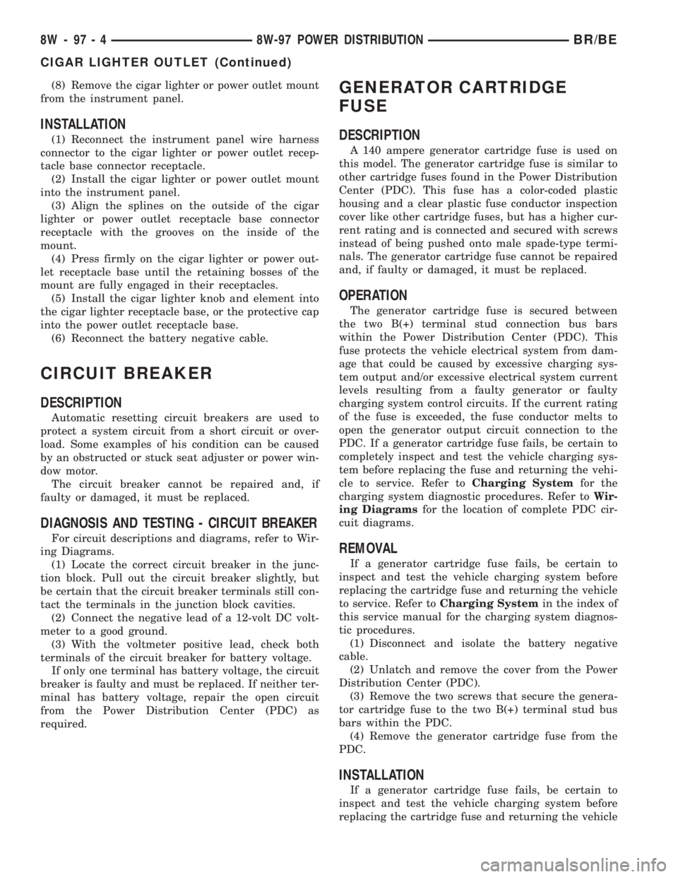
(8) Remove the cigar lighter or power outlet mount
from the instrument panel.
INSTALLATION
(1) Reconnect the instrument panel wire harness
connector to the cigar lighter or power outlet recep-
tacle base connector receptacle.
(2) Install the cigar lighter or power outlet mount
into the instrument panel.
(3) Align the splines on the outside of the cigar
lighter or power outlet receptacle base connector
receptacle with the grooves on the inside of the
mount.
(4) Press firmly on the cigar lighter or power out-
let receptacle base until the retaining bosses of the
mount are fully engaged in their receptacles.
(5) Install the cigar lighter knob and element into
the cigar lighter receptacle base, or the protective cap
into the power outlet receptacle base.
(6) Reconnect the battery negative cable.
CIRCUIT BREAKER
DESCRIPTION
Automatic resetting circuit breakers are used to
protect a system circuit from a short circuit or over-
load. Some examples of his condition can be caused
by an obstructed or stuck seat adjuster or power win-
dow motor.
The circuit breaker cannot be repaired and, if
faulty or damaged, it must be replaced.
DIAGNOSIS AND TESTING - CIRCUIT BREAKER
For circuit descriptions and diagrams, refer to Wir-
ing Diagrams.
(1) Locate the correct circuit breaker in the junc-
tion block. Pull out the circuit breaker slightly, but
be certain that the circuit breaker terminals still con-
tact the terminals in the junction block cavities.
(2) Connect the negative lead of a 12-volt DC volt-
meter to a good ground.
(3) With the voltmeter positive lead, check both
terminals of the circuit breaker for battery voltage.
If only one terminal has battery voltage, the circuit
breaker is faulty and must be replaced. If neither ter-
minal has battery voltage, repair the open circuit
from the Power Distribution Center (PDC) as
required.
GENERATOR CARTRIDGE
FUSE
DESCRIPTION
A 140 ampere generator cartridge fuse is used on
this model. The generator cartridge fuse is similar to
other cartridge fuses found in the Power Distribution
Center (PDC). This fuse has a color-coded plastic
housing and a clear plastic fuse conductor inspection
cover like other cartridge fuses, but has a higher cur-
rent rating and is connected and secured with screws
instead of being pushed onto male spade-type termi-
nals. The generator cartridge fuse cannot be repaired
and, if faulty or damaged, it must be replaced.
OPERATION
The generator cartridge fuse is secured between
the two B(+) terminal stud connection bus bars
within the Power Distribution Center (PDC). This
fuse protects the vehicle electrical system from dam-
age that could be caused by excessive charging sys-
tem output and/or excessive electrical system current
levels resulting from a faulty generator or faulty
charging system control circuits. If the current rating
of the fuse is exceeded, the fuse conductor melts to
open the generator output circuit connection to the
PDC. If a generator cartridge fuse fails, be certain to
completely inspect and test the vehicle charging sys-
tem before replacing the fuse and returning the vehi-
cle to service. Refer toCharging Systemfor the
charging system diagnostic procedures. Refer toWir-
ing Diagramsfor the location of complete PDC cir-
cuit diagrams.
REMOVAL
If a generator cartridge fuse fails, be certain to
inspect and test the vehicle charging system before
replacing the cartridge fuse and returning the vehicle
to service. Refer toCharging Systemin the index of
this service manual for the charging system diagnos-
tic procedures.
(1) Disconnect and isolate the battery negative
cable.
(2) Unlatch and remove the cover from the Power
Distribution Center (PDC).
(3) Remove the two screws that secure the genera-
tor cartridge fuse to the two B(+) terminal stud bus
bars within the PDC.
(4) Remove the generator cartridge fuse from the
PDC.
INSTALLATION
If a generator cartridge fuse fails, be certain to
inspect and test the vehicle charging system before
replacing the cartridge fuse and returning the vehicle
8W - 97 - 4 8W-97 POWER DISTRIBUTIONBR/BE
CIGAR LIGHTER OUTLET (Continued)
Page 1079 of 2255
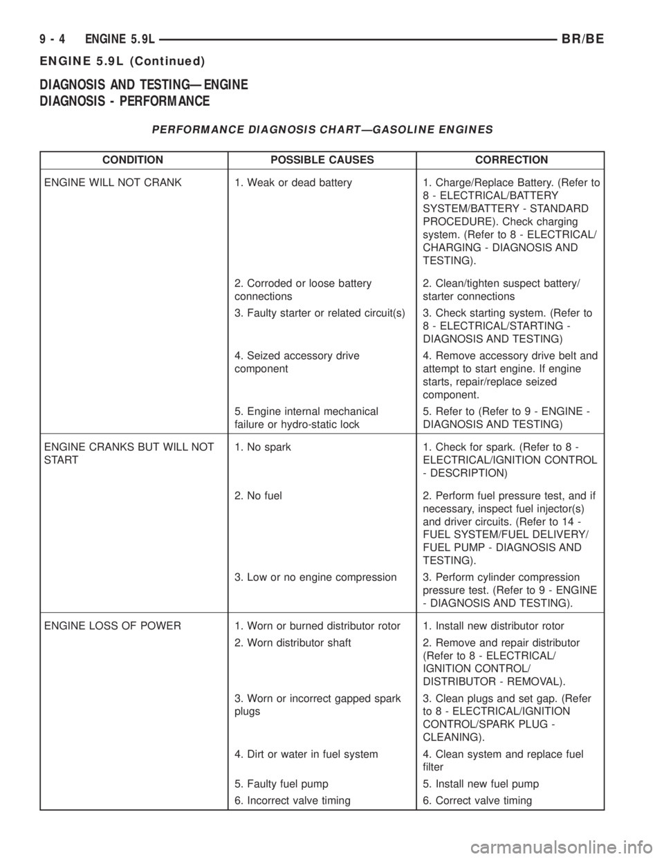
DIAGNOSIS AND TESTINGÐENGINE
DIAGNOSIS - PERFORMANCE
PERFORMANCE DIAGNOSIS CHARTÐGASOLINE ENGINES
CONDITION POSSIBLE CAUSES CORRECTION
ENGINE WILL NOT CRANK 1. Weak or dead battery 1. Charge/Replace Battery. (Refer to
8 - ELECTRICAL/BATTERY
SYSTEM/BATTERY - STANDARD
PROCEDURE). Check charging
system. (Refer to 8 - ELECTRICAL/
CHARGING - DIAGNOSIS AND
TESTING).
2. Corroded or loose battery
connections2. Clean/tighten suspect battery/
starter connections
3. Faulty starter or related circuit(s) 3. Check starting system. (Refer to
8 - ELECTRICAL/STARTING -
DIAGNOSIS AND TESTING)
4. Seized accessory drive
component4. Remove accessory drive belt and
attempt to start engine. If engine
starts, repair/replace seized
component.
5. Engine internal mechanical
failure or hydro-static lock5. Refer to (Refer to 9 - ENGINE -
DIAGNOSIS AND TESTING)
ENGINE CRANKS BUT WILL NOT
START1. No spark 1. Check for spark. (Refer to 8 -
ELECTRICAL/IGNITION CONTROL
- DESCRIPTION)
2. No fuel 2. Perform fuel pressure test, and if
necessary, inspect fuel injector(s)
and driver circuits. (Refer to 14 -
FUEL SYSTEM/FUEL DELIVERY/
FUEL PUMP - DIAGNOSIS AND
TESTING).
3. Low or no engine compression 3. Perform cylinder compression
pressure test. (Refer to 9 - ENGINE
- DIAGNOSIS AND TESTING).
ENGINE LOSS OF POWER 1. Worn or burned distributor rotor 1. Install new distributor rotor
2. Worn distributor shaft 2. Remove and repair distributor
(Refer to 8 - ELECTRICAL/
IGNITION CONTROL/
DISTRIBUTOR - REMOVAL).
3. Worn or incorrect gapped spark
plugs3. Clean plugs and set gap. (Refer
to 8 - ELECTRICAL/IGNITION
CONTROL/SPARK PLUG -
CLEANING).
4. Dirt or water in fuel system 4. Clean system and replace fuel
filter
5. Faulty fuel pump 5. Install new fuel pump
6. Incorrect valve timing 6. Correct valve timing
9 - 4 ENGINE 5.9LBR/BE
ENGINE 5.9L (Continued)
Page 1080 of 2255
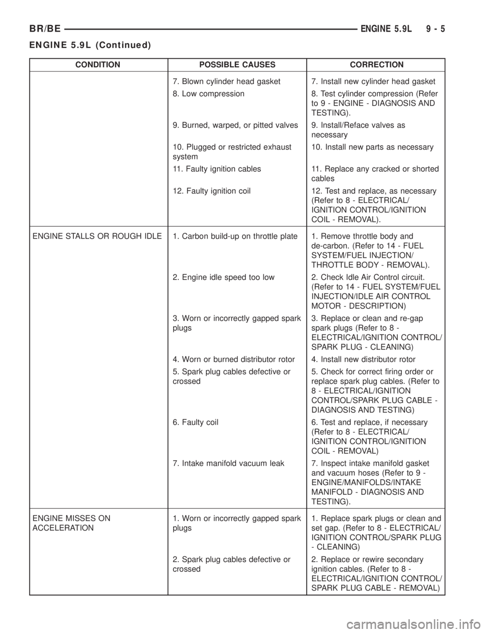
CONDITION POSSIBLE CAUSES CORRECTION
7. Blown cylinder head gasket 7. Install new cylinder head gasket
8. Low compression 8. Test cylinder compression (Refer
to 9 - ENGINE - DIAGNOSIS AND
TESTING).
9. Burned, warped, or pitted valves 9. Install/Reface valves as
necessary
10. Plugged or restricted exhaust
system10. Install new parts as necessary
11. Faulty ignition cables 11. Replace any cracked or shorted
cables
12. Faulty ignition coil 12. Test and replace, as necessary
(Refer to 8 - ELECTRICAL/
IGNITION CONTROL/IGNITION
COIL - REMOVAL).
ENGINE STALLS OR ROUGH IDLE 1. Carbon build-up on throttle plate 1. Remove throttle body and
de-carbon. (Refer to 14 - FUEL
SYSTEM/FUEL INJECTION/
THROTTLE BODY - REMOVAL).
2. Engine idle speed too low 2. Check Idle Air Control circuit.
(Refer to 14 - FUEL SYSTEM/FUEL
INJECTION/IDLE AIR CONTROL
MOTOR - DESCRIPTION)
3. Worn or incorrectly gapped spark
plugs3. Replace or clean and re-gap
spark plugs (Refer to 8 -
ELECTRICAL/IGNITION CONTROL/
SPARK PLUG - CLEANING)
4. Worn or burned distributor rotor 4. Install new distributor rotor
5. Spark plug cables defective or
crossed5. Check for correct firing order or
replace spark plug cables. (Refer to
8 - ELECTRICAL/IGNITION
CONTROL/SPARK PLUG CABLE -
DIAGNOSIS AND TESTING)
6. Faulty coil 6. Test and replace, if necessary
(Refer to 8 - ELECTRICAL/
IGNITION CONTROL/IGNITION
COIL - REMOVAL)
7. Intake manifold vacuum leak 7. Inspect intake manifold gasket
and vacuum hoses (Refer to 9 -
ENGINE/MANIFOLDS/INTAKE
MANIFOLD - DIAGNOSIS AND
TESTING).
ENGINE MISSES ON
ACCELERATION1. Worn or incorrectly gapped spark
plugs1. Replace spark plugs or clean and
set gap. (Refer to 8 - ELECTRICAL/
IGNITION CONTROL/SPARK PLUG
- CLEANING)
2. Spark plug cables defective or
crossed2. Replace or rewire secondary
ignition cables. (Refer to 8 -
ELECTRICAL/IGNITION CONTROL/
SPARK PLUG CABLE - REMOVAL)
BR/BEENGINE 5.9L 9 - 5
ENGINE 5.9L (Continued)