2002 DODGE RAM air condition
[x] Cancel search: air conditionPage 1193 of 2255
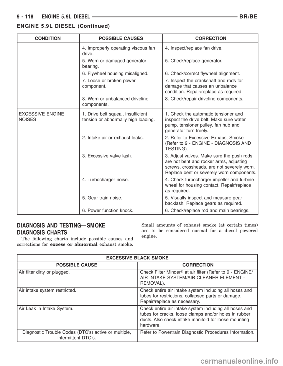
CONDITION POSSIBLE CAUSES CORRECTION
4. Improperly operating viscous fan
drive.4. Inspect/replace fan drive.
5. Worn or damaged generator
bearing.5. Check/replace generator.
6. Flywheel housing misaligned. 6. Check/correct flywheel alignment.
7. Loose or broken power
component.7. Inspect the crankshaft and rods for
damage that causes an unbalance
condition. Repair/replace as required.
8. Worn or unbalanced driveline
components.8. Check/repair driveline components.
EXCESSIVE ENGINE
NOISES1. Drive belt squeal, insufficient
tension or abnormally high loading.1. Check the automatic tensioner and
inspect the drive belt. Make sure water
pump, tensioner pulley, fan hub and
generator turn freely.
2. Intake air or exhaust leaks. 2. Refer to Excessive Exhaust Smoke
(Refer to 9 - ENGINE - DIAGNOSIS AND
TESTING).
3. Excessive valve lash. 3. Adjust valves. Make sure the push rods
are not bent and rocker arms, adjusting
screws, crossheads, are not severely worn.
Replace bent or severely worn components.
4. Turbocharger noise. 4. Check turbocharger impeller and turbine
wheel for housing contact. Repair/replace
as required.
5. Gear train noise. 5. Visually inspect and measure gear
backlash. Replace gears as required.
6. Power function knock. 6. Check/replace rod and main bearings.
DIAGNOSIS AND TESTINGÐSMOKE
DIAGNOSIS CHARTS
The following charts include possible causes and
corrections forexcess or abnormalexhaust smoke.Small amounts of exhaust smoke (at certain times)
are to be considered normal for a diesel powered
engine.
EXCESSIVE BLACK SMOKE
POSSIBLE CAUSE CORRECTION
Air filter dirty or plugged. Check Filter MinderTat air filter (Refer to 9 - ENGINE/
AIR INTAKE SYSTEM/AIR CLEANER ELEMENT -
REMOVAL).
Air intake system restricted. Check entire air intake system including all hoses and
tubes for restrictions, collapsed parts or damage.
Repair/replace as necessary.
Air Leak in Intake System. Check entire air intake system including all hoses and
tubes for cracks, loose clamps and/or holes in rubber
ducts. Also check intake manifold for loose mounting
hardware.
Diagnostic Trouble Codes (DTC's) active or multiple,
intermittent DTC's.Refer to Powertrain Diagnostic Procedures Information.
9 - 118 ENGINE 5.9L DIESELBR/BE
ENGINE 5.9L DIESEL (Continued)
Page 1194 of 2255
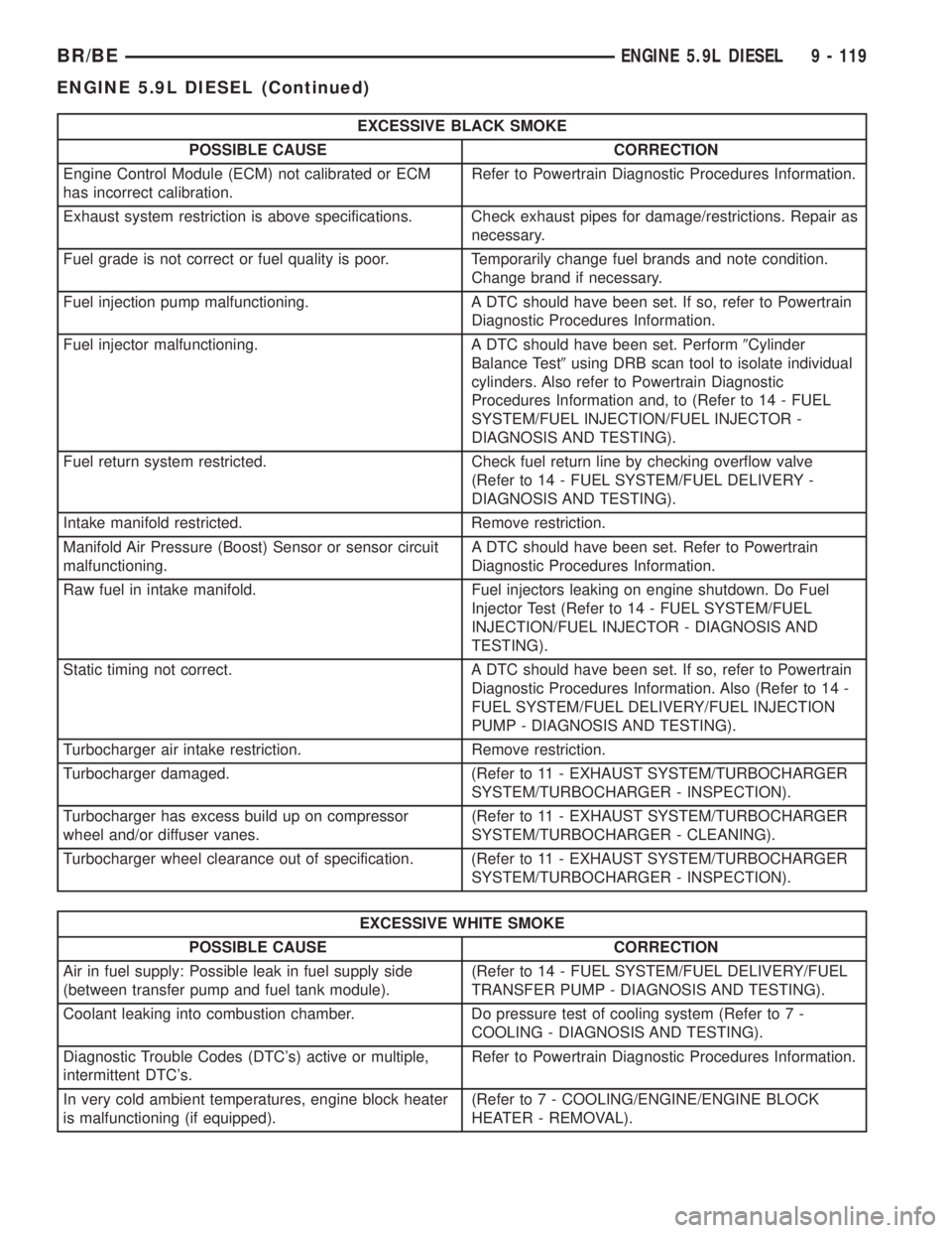
EXCESSIVE BLACK SMOKE
POSSIBLE CAUSE CORRECTION
Engine Control Module (ECM) not calibrated or ECM
has incorrect calibration.Refer to Powertrain Diagnostic Procedures Information.
Exhaust system restriction is above specifications. Check exhaust pipes for damage/restrictions. Repair as
necessary.
Fuel grade is not correct or fuel quality is poor. Temporarily change fuel brands and note condition.
Change brand if necessary.
Fuel injection pump malfunctioning. A DTC should have been set. If so, refer to Powertrain
Diagnostic Procedures Information.
Fuel injector malfunctioning. A DTC should have been set. Perform9Cylinder
Balance Test9using DRB scan tool to isolate individual
cylinders. Also refer to Powertrain Diagnostic
Procedures Information and, to (Refer to 14 - FUEL
SYSTEM/FUEL INJECTION/FUEL INJECTOR -
DIAGNOSIS AND TESTING).
Fuel return system restricted. Check fuel return line by checking overflow valve
(Refer to 14 - FUEL SYSTEM/FUEL DELIVERY -
DIAGNOSIS AND TESTING).
Intake manifold restricted. Remove restriction.
Manifold Air Pressure (Boost) Sensor or sensor circuit
malfunctioning.A DTC should have been set. Refer to Powertrain
Diagnostic Procedures Information.
Raw fuel in intake manifold. Fuel injectors leaking on engine shutdown. Do Fuel
Injector Test (Refer to 14 - FUEL SYSTEM/FUEL
INJECTION/FUEL INJECTOR - DIAGNOSIS AND
TESTING).
Static timing not correct. A DTC should have been set. If so, refer to Powertrain
Diagnostic Procedures Information. Also (Refer to 14 -
FUEL SYSTEM/FUEL DELIVERY/FUEL INJECTION
PUMP - DIAGNOSIS AND TESTING).
Turbocharger air intake restriction. Remove restriction.
Turbocharger damaged. (Refer to 11 - EXHAUST SYSTEM/TURBOCHARGER
SYSTEM/TURBOCHARGER - INSPECTION).
Turbocharger has excess build up on compressor
wheel and/or diffuser vanes.(Refer to 11 - EXHAUST SYSTEM/TURBOCHARGER
SYSTEM/TURBOCHARGER - CLEANING).
Turbocharger wheel clearance out of specification. (Refer to 11 - EXHAUST SYSTEM/TURBOCHARGER
SYSTEM/TURBOCHARGER - INSPECTION).
EXCESSIVE WHITE SMOKE
POSSIBLE CAUSE CORRECTION
Air in fuel supply: Possible leak in fuel supply side
(between transfer pump and fuel tank module).(Refer to 14 - FUEL SYSTEM/FUEL DELIVERY/FUEL
TRANSFER PUMP - DIAGNOSIS AND TESTING).
Coolant leaking into combustion chamber. Do pressure test of cooling system (Refer to 7 -
COOLING - DIAGNOSIS AND TESTING).
Diagnostic Trouble Codes (DTC's) active or multiple,
intermittent DTC's.Refer to Powertrain Diagnostic Procedures Information.
In very cold ambient temperatures, engine block heater
is malfunctioning (if equipped).(Refer to 7 - COOLING/ENGINE/ENGINE BLOCK
HEATER - REMOVAL).
BR/BEENGINE 5.9L DIESEL 9 - 119
ENGINE 5.9L DIESEL (Continued)
Page 1195 of 2255
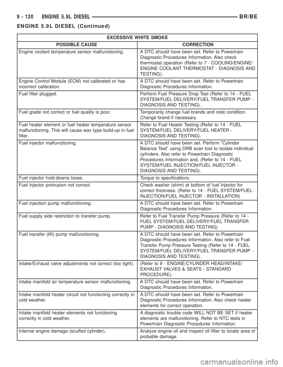
EXCESSIVE WHITE SMOKE
POSSIBLE CAUSE CORRECTION
Engine coolant temperature sensor malfunctioning. A DTC should have been set. Refer to Powertrain
Diagnostic Procedures Information. Also check
thermostat operation (Refer to 7 - COOLING/ENGINE/
ENGINE COOLANT THERMOSTAT - DIAGNOSIS AND
TESTING).
Engine Control Module (ECM) not calibrated or has
incorrect calibration.A DTC should have been set. Refer to Powertrain
Diagnostic Procedures Information.
Fuel filter plugged. Perform Fuel Pressure Drop Test (Refer to 14 - FUEL
SYSTEM/FUEL DELIVERY/FUEL TRANSFER PUMP -
DIAGNOSIS AND TESTING).
Fuel grade not correct or fuel quality is poor. Temporarily change fuel brands and note condition.
Change brand if necessary.
Fuel heater element or fuel heater temperature sensor
malfunctioning. This will cause wax type build-up in fuel
filter.Refer to Fuel Heater Testing (Refer to 14 - FUEL
SYSTEM/FUEL DELIVERY/FUEL HEATER -
DIAGNOSIS AND TESTING).
Fuel injector malfunctioning. A DTC should have been set. Perform9Cylinder
Balance Test9using DRB scan tool to isolate individual
cylinders. Also refer to Powertrain Diagnostic
Procedures Information and, (Refer to 14 - FUEL
SYSTEM/FUEL INJECTION/FUEL INJECTOR -
DIAGNOSIS AND TESTING).
Fuel injector hold-downs loose. Torque to specifications.
Fuel injector protrusion not correct. Check washer (shim) at bottom of fuel injector for
correct thickness. (Refer to 14 - FUEL SYSTEM/FUEL
INJECTION/FUEL INJECTOR - INSTALLATION)
Fuel injection pump malfunctioning. A DTC should have been set. Refer to Powertrain
Diagnostic Procedures Information.
Fuel supply side restriction to transfer pump. Refer to Fuel Transfer Pump Pressure (Refer to 14 -
FUEL SYSTEM/FUEL DELIVERY/FUEL TRANSFER
PUMP - DIAGNOSIS AND TESTING)
Fuel transfer (lift) pump malfunctioning. A DTC should have been set. Refer to Powertrain
Diagnostic Procedures Information. Also refer to Fuel
Transfer Pump Pressure Testing (Refer to 14 - FUEL
SYSTEM/FUEL DELIVERY/FUEL TRANSFER PUMP -
DIAGNOSIS AND TESTING).
Intake/Exhaust valve adjustments not correct (too tight). (Refer to 9 - ENGINE/CYLINDER HEAD/INTAKE/
EXHAUST VALVES & SEATS - STANDARD
PROCEDURE).
Intake manifold air temperature sensor malfunctioning. A DTC should have been set. Refer to Powertrain
Diagnostic Procedures Information.
Intake manifold heater circuit not functioning correctly in
cold weather.A DTC should have been set. Refer to Powertrain
Diagnostic Procedures Information. Also check heater
elements for correct operation.
Intake manifold heater elements not functioning
correctly in cold weather.A diagnostic trouble code WILL NOT BE SET if heater
elements are malfunctioning. Refer to NTC tests in
Powertrain Diagnostic Procedures Information.
Internal engine damage (scuffed cylinder). Analyze engine oil and inspect oil filter to locate area of
probable damage.
9 - 120 ENGINE 5.9L DIESELBR/BE
ENGINE 5.9L DIESEL (Continued)
Page 1198 of 2255
(1) Disconnect the negative cable(s) from the bat-
tery.
(2) Inspect air cleaner, induction system, and
intake manifold to ensure system is dry and clear of
foreign material.
(3) Place a shop towel around the fuel injectors to
catch any fluid that may possibly be under pressure
in the cylinder head. Remove the fuel injectors (Refer
to 14 - FUEL SYSTEM/FUEL INJECTION/FUEL
INJECTOR - REMOVAL).
(4) With all injectors removed, rotate the crank-
shaft using a breaker bar and socket.
(5) Identify the fluid in the cylinders (coolant, fuel,
oil, etc.).
(6) Be sure all fluid has been removed from the
cylinders.
(7) Repair engine or components as necessary to
prevent this problem from occurring again.
(8) Squirt a small amount of engine oil into the
cylinders to lubricate the walls. This will prevent
damage on restart.
(9) Install new fuel injectors (Refer to 14 - FUEL
SYSTEM/FUEL INJECTION/FUEL INJECTOR -
INSTALLATION).
(10) Drain engine oil. Remove and discard the oil
filter (Refer to 9 - ENGINE/LUBRICATION/OIL FIL-
TER - REMOVAL).
(11) Install the drain plug. Tighten the plug to 34
N´m (25 ft. lbs.) torque.
(12) Install a new oil filter (Refer to 9 - ENGINE/
LUBRICATION/OIL FILTER - INSTALLATION).
(13) Fill engine crankcase with the specified
amount and grade of oil (Refer to LUBRICATION &
MAINTENANCE/FLUID TYPES - SPECIFICA-
TIONS).
(14) Connect the negative cable(s) to the battery.
(15) Start the engine and check for any leaks.
REMOVAL
REMOVALÐENGINE
(1) Disconnect both battery negative cables.
(2) Recover A/C refrigerant (if A/C equipped) (Refer
to 24 - HEATING & AIR CONDITIONING/PLUMB-
ING - STANDARD PROCEDURE).
(3) Raise vehicle on hoist.
(4) Drain engine coolant (Refer to 7 - COOLING -
STANDARD PROCEDURE).
(5) Remove engine oil drain plug and drain engine
oil.
(6) Lower vehicle.
(7) Remove radiator upper hose.
(8) Remove the cooling fan shroud-to-radiator
mounting bolts.(9) Remove viscous fan/drive assembly (Refer to 7 -
COOLING/ENGINE/RADIATOR FAN - REMOVAL).
Remove the cooling fan and shroud together.
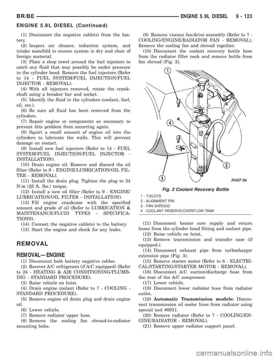
(10) Disconnect the coolant recovery bottle hose
from the radiator filler neck and remove bottle from
fan shroud (Fig. 2).
(11) Disconnect heater core supply and return
hoses from the cylinder head fitting and coolant pipe.
(12) Raise vehicle on hoist.
(13) Remove transmission and transfer case (if
equipped.).
(14) Disconnect exhaust pipe from turbocharger
extension pipe (Fig. 3).
(15) Remove starter motor (Refer to 8 - ELECTRI-
CAL/STARTING/STARTER MOTOR - REMOVAL).
(16) Disconnect A/C suction/discharge hose from
the rear of the A/C compressor.
(17) Lower vehicle.
(18) Disconnect lower radiator hose from radiator
outlet.
(19)Automatic Transmission models:Discon-
nect transmission oil cooler lines from radiator using
special tool #6931.
(20) Remove radiator (Refer to 7 - COOLING/EN-
GINE/RADIATOR - REMOVAL).
(21) Remove upper radiator support panel.
Fig. 2 Coolant Recovery Bottle
1 - T-SLOTS
2 - ALIGNMENT PIN
3 - FAN SHROUD
4 - COOLANT RESERVE/OVERFLOW TANK
BR/BEENGINE 5.9L DIESEL 9 - 123
ENGINE 5.9L DIESEL (Continued)
Page 1205 of 2255
CAUTION: Certain engine degreasers or cleaners
may discolor or damage the plastic housing of the
Filter Minder. Cover and tape the Filter Minder if any
engine degreasers or cleaners are to be used.
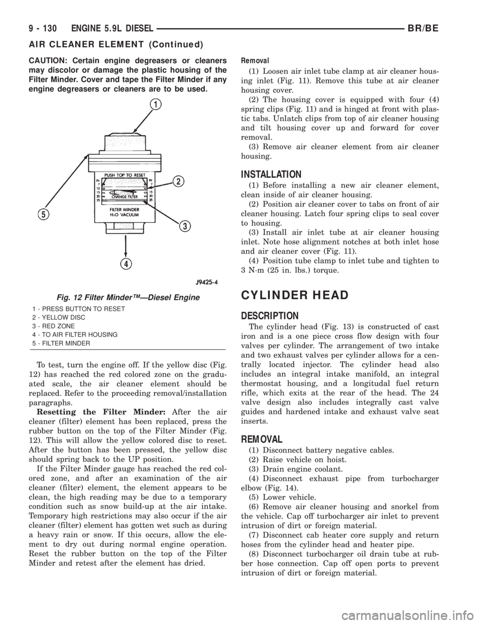
To test, turn the engine off. If the yellow disc (Fig.
12) has reached the red colored zone on the gradu-
ated scale, the air cleaner element should be
replaced. Refer to the proceeding removal/installation
paragraphs.
Resetting the Filter Minder:After the air
cleaner (filter) element has been replaced, press the
rubber button on the top of the Filter Minder (Fig.
12). This will allow the yellow colored disc to reset.
After the button has been pressed, the yellow disc
should spring back to the UP position.
If the Filter Minder gauge has reached the red col-
ored zone, and after an examination of the air
cleaner (filter) element, the element appears to be
clean, the high reading may be due to a temporary
condition such as snow build-up at the air intake.
Temporary high restrictions may also occur if the air
cleaner (filter) element has gotten wet such as during
a heavy rain or snow. If this occurs, allow the ele-
ment to dry out during normal engine operation.
Reset the rubber button on the top of the Filter
Minder and retest after the element has dried.Removal
(1) Loosen air inlet tube clamp at air cleaner hous-
ing inlet (Fig. 11). Remove this tube at air cleaner
housing cover.
(2) The housing cover is equipped with four (4)
spring clips (Fig. 11) and is hinged at front with plas-
tic tabs. Unlatch clips from top of air cleaner housing
and tilt housing cover up and forward for cover
removal.
(3) Remove air cleaner element from air cleaner
housing.
INSTALLATION
(1) Before installing a new air cleaner element,
clean inside of air cleaner housing.
(2) Position air cleaner cover to tabs on front of air
cleaner housing. Latch four spring clips to seal cover
to housing.
(3) Install air inlet tube at air cleaner housing
inlet. Note hose alignment notches at both inlet hose
and air cleaner cover (Fig. 11).
(4) Position tube clamp to inlet tube and tighten to
3 N´m (25 in. lbs.) torque.
CYLINDER HEAD
DESCRIPTION
The cylinder head (Fig. 13) is constructed of cast
iron and is a one piece cross flow design with four
valves per cylinder. The arrangement of two intake
and two exhaust valves per cylinder allows for a cen-
trally located injector. The cylinder head also
includes an integral intake manifold, an integral
thermostat housing, and a longitudal fuel return
rifle, which exits at the rear of the head. The 24
valve design also includes integrally cast valve
guides and hardened intake and exhaust valve seat
inserts.
REMOVAL
(1) Disconnect battery negative cables.
(2) Raise vehicle on hoist.
(3) Drain engine coolant.
(4) Disconnect exhaust pipe from turbocharger
elbow (Fig. 14).
(5) Lower vehicle.
(6) Remove air cleaner housing and snorkel from
the vehicle. Cap off turbocharger air inlet to prevent
intrusion of dirt or foreign material.
(7) Disconnect cab heater core supply and return
hoses from the cylinder head and heater pipe.
(8) Disconnect turbocharger oil drain tube at rub-
ber hose connection. Cap off open ports to prevent
intrusion of dirt or foreign material.
Fig. 12 Filter MinderŸÐDiesel Engine
1 - PRESS BUTTON TO RESET
2 - YELLOW DISC
3 - RED ZONE
4 - TO AIR FILTER HOUSING
5 - FILTER MINDER
9 - 130 ENGINE 5.9L DIESELBR/BE
AIR CLEANER ELEMENT (Continued)
Page 1227 of 2255
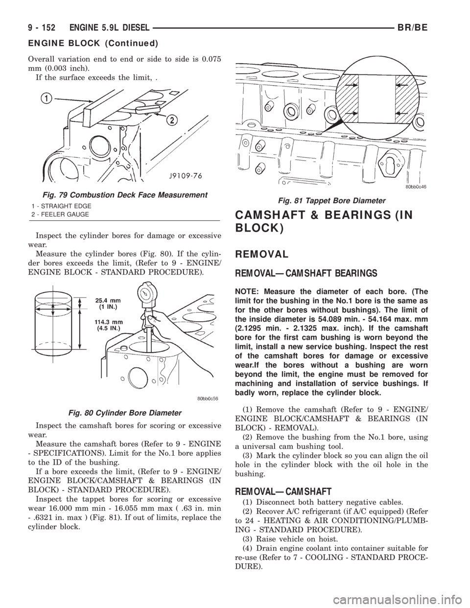
Overall variation end to end or side to side is 0.075
mm (0.003 inch).
If the surface exceeds the limit, .
Inspect the cylinder bores for damage or excessive
wear.
Measure the cylinder bores (Fig. 80). If the cylin-
der bores exceeds the limit, (Refer to 9 - ENGINE/
ENGINE BLOCK - STANDARD PROCEDURE).
Inspect the camshaft bores for scoring or excessive
wear.
Measure the camshaft bores (Refer to 9 - ENGINE
- SPECIFICATIONS). Limit for the No.1 bore applies
to the ID of the bushing.
If a bore exceeds the limit, (Refer to 9 - ENGINE/
ENGINE BLOCK/CAMSHAFT & BEARINGS (IN
BLOCK) - STANDARD PROCEDURE).
Inspect the tappet bores for scoring or excessive
wear 16.000 mm min - 16.055 mm max ( .63 in. min
- .6321 in. max ) (Fig. 81). If out of limits, replace the
cylinder block.
CAMSHAFT & BEARINGS (IN
BLOCK)
REMOVAL
REMOVALÐCAMSHAFT BEARINGS
NOTE: Measure the diameter of each bore. (The
limit for the bushing in the No.1 bore is the same as
for the other bores without bushings). The limit of
the inside diameter is 54.089 min. - 54.164 max. mm
(2.1295 min. - 2.1325 max. inch). If the camshaft
bore for the first cam bushing is worn beyond the
limit, install a new service bushing. Inspect the rest
of the camshaft bores for damage or excessive
wear.If the bores without a bushing are worn
beyond the limit, the engine must be removed for
machining and installation of service bushings. If
badly worn, replace the cylinder block.
(1) Remove the camshaft (Refer to 9 - ENGINE/
ENGINE BLOCK/CAMSHAFT & BEARINGS (IN
BLOCK) - REMOVAL).
(2) Remove the bushing from the No.1 bore, using
a universal cam bushing tool.
(3) Mark the cylinder block so you can align the oil
hole in the cylinder block with the oil hole in the
bushing.
REMOVALÐCAMSHAFT
(1) Disconnect both battery negative cables.
(2) Recover A/C refrigerant (if A/C equipped) (Refer
to 24 - HEATING & AIR CONDITIONING/PLUMB-
ING - STANDARD PROCEDURE).
(3) Raise vehicle on hoist.
(4) Drain engine coolant into container suitable for
re-use (Refer to 7 - COOLING - STANDARD PROCE-
DURE).
Fig. 79 Combustion Deck Face Measurement
1 - STRAIGHT EDGE
2 - FEELER GAUGE
Fig. 80 Cylinder Bore Diameter
Fig. 81 Tappet Bore Diameter
9 - 152 ENGINE 5.9L DIESELBR/BE
ENGINE BLOCK (Continued)
Page 1254 of 2255
(3) Always check the condition of the used oil. This
can give you an indication of engine problems that
might exist.
²Thin, black oil indicates fuel dilution.
²Milky discoloration indicates coolant dilution.
(4) Clean the area around the oil filter head.
Remove the filter (Refer to 9 - ENGINE/LUBRICA-
TION/OIL FILTER - REMOVAL).
(5) Install new oil filter (Refer to 9 - ENGINE/LU-
BRICATION/OIL FILTER - INSTALLATION).
(6) Clean the drain plug and the sealing surface of
the pan. Check the condition of the threads and seal-
ing surface on the oil pan and drain plug.
(7) Install the drain plug. Tighten the plug to 50
N´m (37 ft. lbs.) torque.
(8) Use only High-Quality Multi-Viscosity lubricat-
ing oil in the Cummins Turbo Diesel engine. Choose
the correct oil for the operating conditions (Refer to
LUBRICATION & MAINTENANCE/FLUID TYPES -
DESCRIPTION).
(9) Fill the engine with the correct grade of new oil
(Refer to LUBRICATION & MAINTENANCE/FLUID
CAPACITIES - SPECIFICATIONS).
(10) Start the engine and operate it at idle for sev-
eral minutes. Check for leaks at the filter and drain
plug.
(11) Stop engine. Wait several minutes to allow the
oil to drain back to the pan and check the level
again.
USED ENGINE OIL DISPOSAL Care should be
exercised when disposing of used engine oil after
it has been drained from a vehicle's engine.
OIL COOLER & LINES
CLEANING AND INSPECTION
Clean the sealing surfaces.
Apply 483 kPa (70 psi) air pressure to the element
to check for leaks. If the element leaks, replace the
element.
OIL FILTER
REMOVAL
(1) Clean the area around the oil filter head.
Remove the filter using a 90-95 mm filter wrench.
(2) Clean the gasket surface of the filter head. The
filter canister O-Ring seal can stick on the filter
head. Make sure it is removed.
INSTALLATION
(1) Fill the oil filter element with clean oil before
installation. Use the same type oil that will be used
in the engine.
(2) Apply a light film of lubricating oil to the seal-
ing surface before installing the filter.
CAUTION: Mechanical over-tightening may distort
the threads or damage the filter element seal.
(3) Install the filter until it contacts the sealing
surface of the oil filter adapter. Tighten filter an
additional ó turn.
OIL PAN
REMOVAL
(1) Disconnect the battery negative cables.
(2) Raise vehicle on hoist.
(3) Remove transmission and transfer case (if
equipped).
(4) Remove flywheel.
(5) Disconnect starter cables from starter motor.
(6) Remove starter motor (Refer to 8 - ELECTRI-
CAL/STARTING/STARTER MOTOR - REMOVAL)
and transmission adapter plate assembly.
WARNING: HOT OIL CAN CAUSE PERSONAL
INJURY.
(7) Drain the engine oil (Refer to 9 - ENGINE/LU-
BRICATION/OIL - STANDARD PROCEDURE).
(8) Install the oil pan drain plug with a new seal-
ing washer and tighten to 60 N´m (44 ft. lbs.) torque.
(9) Remove oil pan bolts, break the pan to block
seal, and lower pan slightly and remove oil suction
tube fasteners.
(10) Remove oil pan and suction tube (Fig. 151).
CLEANING
Remove all gasket material from the oil pan and
cylinder block sealing surfaces. Extra effort may be
required around T-joint areas. Clean oil pan and
flush suction tube with a suitable solvent.
INSPECTION
Inspect the oil pan, suction tube, and tube braces
for cracks and damage. Replace any defective compo-
nent. Inspect the oil drain plug and drain hole
threads. Inspect the oil pan sealing surface for
straightness. Repair any minor imperfections with a
ball-peen hammer. Do not attempt to repair an oil
pan by welding.
BR/BEENGINE 5.9L DIESEL 9 - 179
OIL (Continued)
Page 1280 of 2255
INSTALLATION
(1) Install the tailpipe into the muffler.
(2) Install the tailpipe hanger rods into the isola-
tors (Fig. 16).
(3) Install the exhaust clamp, align the exhaust
system, and tighten the clamp 48 N´m (35 ft. lbs.)
torque.
(4) Lower the vehicle.
(5) Connect the battery negative cables.
(6) Start the engine and inspect for exhaust leaks
and exhaust system contact with the body panels.
Adjust the alignment, if needed.
RESONATOR
REMOVAL
(1) Disconnect the battery negative cables.
(2) Raise vehicle on hoist.
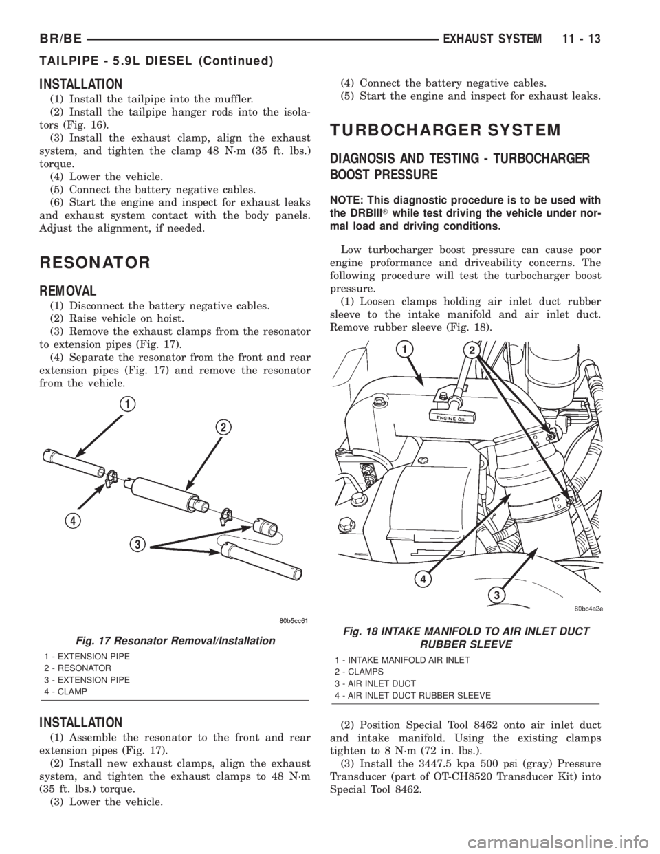
(3) Remove the exhaust clamps from the resonator
to extension pipes (Fig. 17).
(4) Separate the resonator from the front and rear
extension pipes (Fig. 17) and remove the resonator
from the vehicle.
INSTALLATION
(1) Assemble the resonator to the front and rear
extension pipes (Fig. 17).
(2) Install new exhaust clamps, align the exhaust
system, and tighten the exhaust clamps to 48 N´m
(35 ft. lbs.) torque.
(3) Lower the vehicle.(4) Connect the battery negative cables.
(5) Start the engine and inspect for exhaust leaks.
TURBOCHARGER SYSTEM
DIAGNOSIS AND TESTING - TURBOCHARGER
BOOST PRESSURE
NOTE: This diagnostic procedure is to be used with
the DRBIIITwhile test driving the vehicle under nor-
mal load and driving conditions.
Low turbocharger boost pressure can cause poor
engine proformance and driveability concerns. The
following procedure will test the turbocharger boost
pressure.
(1) Loosen clamps holding air inlet duct rubber
sleeve to the intake manifold and air inlet duct.
Remove rubber sleeve (Fig. 18).
(2) Position Special Tool 8462 onto air inlet duct
and intake manifold. Using the existing clamps
tighten to 8 N´m (72 in. lbs.).
(3) Install the 3447.5 kpa 500 psi (gray) Pressure
Transducer (part of OT-CH8520 Transducer Kit) into
Special Tool 8462.
Fig. 17 Resonator Removal/Installation
1 - EXTENSION PIPE
2 - RESONATOR
3 - EXTENSION PIPE
4 - CLAMP
Fig. 18 INTAKE MANIFOLD TO AIR INLET DUCT
RUBBER SLEEVE
1 - INTAKE MANIFOLD AIR INLET
2 - CLAMPS
3 - AIR INLET DUCT
4 - AIR INLET DUCT RUBBER SLEEVE
BR/BEEXHAUST SYSTEM 11 - 13
TAILPIPE - 5.9L DIESEL (Continued)