2002 DODGE RAM air condition
[x] Cancel search: air conditionPage 1283 of 2255
CAUTION: The turbocharger is only serviced as an
assembly. Do not attempt to repair the turbocharger
as turbocharger and/or engine damage can result.
CLEANING
Clean the turbocharger and exhaust manifold
mounting surfaces with a suitable scraper.
INSPECTION
Visually inspect the turbocharger and exhaust
manifold gasket surfaces. Replace stripped or eroded
mounting studs.
(1) Visually inspect the turbocharger for cracks.
The following cracks are NOT acceptable:
²Cracks in the turbine and compressor housing
that go completely through.
²Cracks in the mounting flange that are longer
than 15 mm (0.6 in.).
²Cracks in the mounting flange that intersect
bolt through-holes.
²Two (2) Cracks in the mounting flange that are
closer than 6.4 mm (0.25 in.) together.
(2) Visually inspect the impeller and compressor
wheel fins for nicks, cracks, or chips. Note: Some
impellers may have a factory placed paint mark
which, after normal operation, appears to be a crack.
Remove this mark with a suitable solvent to verify
that it is not a crack.
(3) Visually inspect the turbocharger compressor
housing for an impeller rubbing condition (Fig. 26).
Replace the turbocharger if the condition exists.
(4) Measure the turbocharger axial end play:
(a) Install a dial indicator as shown in (Fig. 27).
Zero the indicator at one end of travel.
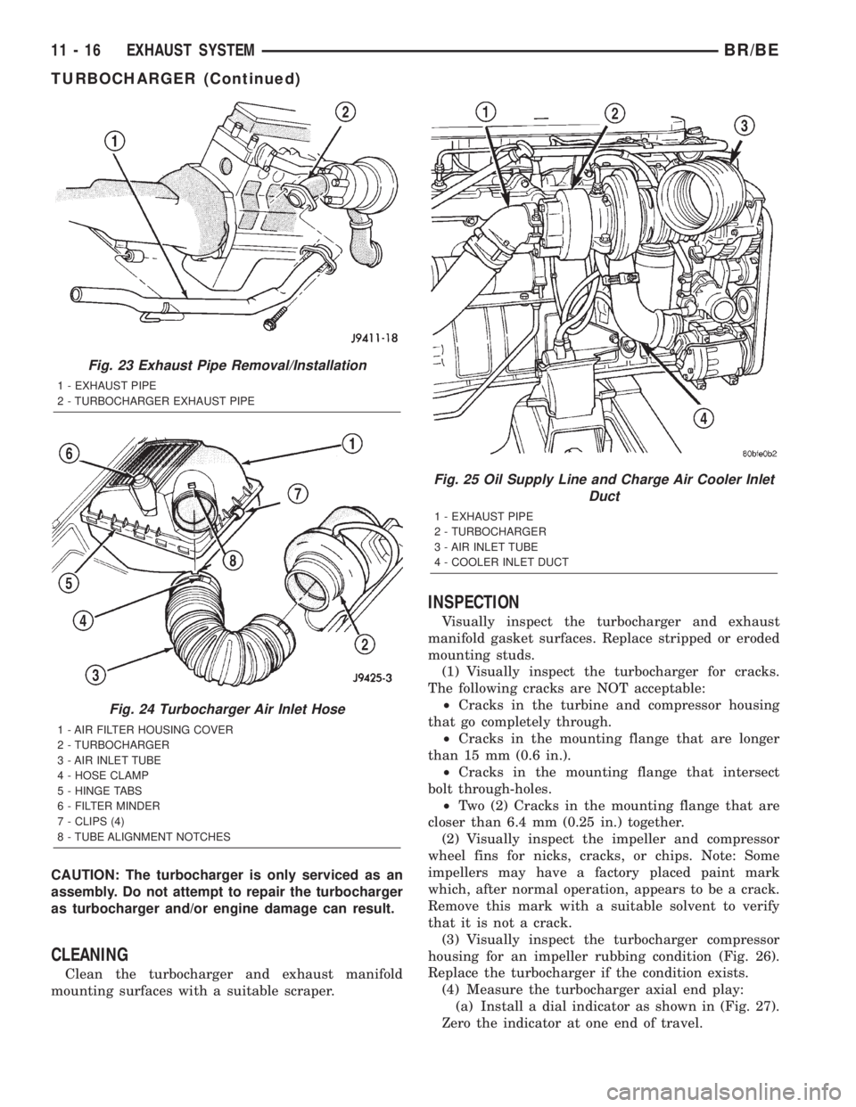
Fig. 23 Exhaust Pipe Removal/Installation
1 - EXHAUST PIPE
2 - TURBOCHARGER EXHAUST PIPE
Fig. 24 Turbocharger Air Inlet Hose
1 - AIR FILTER HOUSING COVER
2 - TURBOCHARGER
3 - AIR INLET TUBE
4 - HOSE CLAMP
5 - HINGE TABS
6 - FILTER MINDER
7 - CLIPS (4)
8 - TUBE ALIGNMENT NOTCHES
Fig. 25 Oil Supply Line and Charge Air Cooler Inlet
Duct
1 - EXHAUST PIPE
2 - TURBOCHARGER
3 - AIR INLET TUBE
4 - COOLER INLET DUCT
11 - 16 EXHAUST SYSTEMBR/BE
TURBOCHARGER (Continued)
Page 1284 of 2255
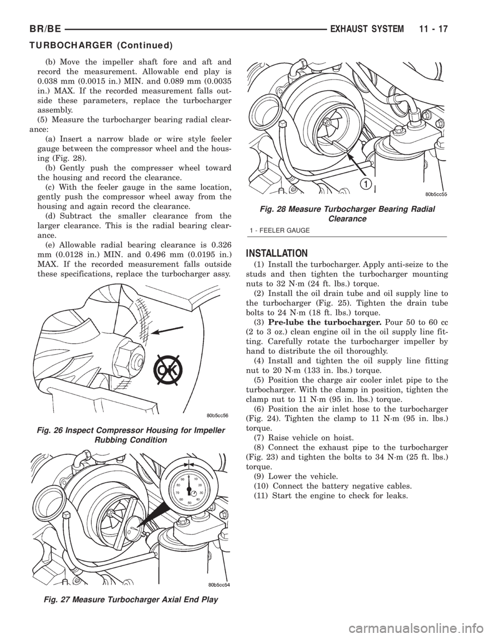
(b) Move the impeller shaft fore and aft and
record the measurement. Allowable end play is
0.038 mm (0.0015 in.) MIN. and 0.089 mm (0.0035
in.) MAX. If the recorded measurement falls out-
side these parameters, replace the turbocharger
assembly.
(5) Measure the turbocharger bearing radial clear-
ance:
(a) Insert a narrow blade or wire style feeler
gauge between the compressor wheel and the hous-
ing (Fig. 28).
(b) Gently push the compresser wheel toward
the housing and record the clearance.
(c) With the feeler gauge in the same location,
gently push the compressor wheel away from the
housing and again record the clearance.
(d) Subtract the smaller clearance from the
larger clearance. This is the radial bearing clear-
ance.
(e) Allowable radial bearing clearance is 0.326
mm (0.0128 in.) MIN. and 0.496 mm (0.0195 in.)
MAX. If the recorded measurement falls outside
these specifications, replace the turbocharger assy.
INSTALLATION
(1) Install the turbocharger. Apply anti-seize to the
studs and then tighten the turbocharger mounting
nuts to 32 N´m (24 ft. lbs.) torque.
(2) Install the oil drain tube and oil supply line to
the turbocharger (Fig. 25). Tighten the drain tube
bolts to 24 N´m (18 ft. lbs.) torque.
(3)Pre-lube the turbocharger.Pour 50 to 60 cc
(2 to 3 oz.) clean engine oil in the oil supply line fit-
ting. Carefully rotate the turbocharger impeller by
hand to distribute the oil thoroughly.
(4) Install and tighten the oil supply line fitting
nut to 20 N´m (133 in. lbs.) torque.
(5) Position the charge air cooler inlet pipe to the
turbocharger. With the clamp in position, tighten the
clamp nut to 11 N´m (95 in. lbs.) torque.
(6) Position the air inlet hose to the turbocharger
(Fig. 24). Tighten the clamp to 11 N´m (95 in. lbs.)
torque.
(7) Raise vehicle on hoist.
(8) Connect the exhaust pipe to the turbocharger
(Fig. 23) and tighten the bolts to 34 N´m (25 ft. lbs.)
torque.
(9) Lower the vehicle.
(10) Connect the battery negative cables.
(11) Start the engine to check for leaks.
Fig. 26 Inspect Compressor Housing for Impeller
Rubbing Condition
Fig. 27 Measure Turbocharger Axial End Play
Fig. 28 Measure Turbocharger Bearing Radial
Clearance
1 - FEELER GAUGE
BR/BEEXHAUST SYSTEM 11 - 17
TURBOCHARGER (Continued)
Page 1286 of 2255
(4) Discharge the A/C system (Refer to 24 - HEAT-
ING & AIR CONDITIONING/PLUMBING - STAN-
DARD PROCEDURE) and remove the A/C condenser
(Refer to 24 - HEATING & AIR CONDITIONING/
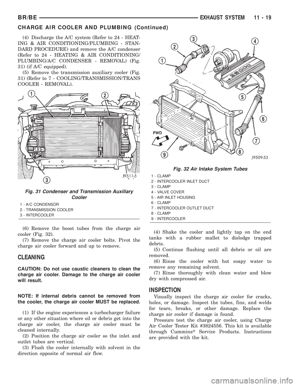
PLUMBING/A/C CONDENSER - REMOVAL) (Fig.
31) (if A/C equipped).
(5) Remove the transmission auxiliary cooler (Fig.
31) (Refer to 7 - COOLING/TRANSMISSION/TRANS
COOLER - REMOVAL).
(6) Remove the boost tubes from the charge air
cooler (Fig. 32).
(7) Remove the charge air cooler bolts. Pivot the
charge air cooler forward and up to remove.
CLEANING
CAUTION: Do not use caustic cleaners to clean the
charge air cooler. Damage to the charge air cooler
will result.
NOTE: If internal debris cannot be removed from
the cooler, the charge air cooler MUST be replaced.
(1) If the engine experiences a turbocharger failure
or any other situation where oil or debris get into the
charge air cooler, the charge air cooler must be
cleaned internally.
(2) Position the charge air cooler so the inlet and
outlet tubes are vertical.
(3) Flush the cooler internally with solvent in the
direction opposite of normal air flow.(4) Shake the cooler and lightly tap on the end
tanks with a rubber mallet to dislodge trapped
debris.
(5) Continue flushing until all debris or oil are
removed.
(6) Rinse the cooler with hot soapy water to
remove any remaining solvent.
(7) Rinse thoroughly with clean water and blow
dry with compressed air.
INSPECTION
Visually inspect the charge air cooler for cracks,
holes, or damage. Inspect the tubes, fins, and welds
for tears, breaks, or other damage. Replace the
charge air cooler if damage is found.
Pressure test the charge air cooler, using Charge
Air Cooler Tester Kit #3824556. This kit is available
through CumminstService Products. Instructions
are provided with the kit.
Fig. 31 Condenser and Transmission Auxiliary
Cooler
1 - A/C CONDENSOR
2 - TRANSMISSION COOLER
3 - INTERCOOLER
Fig. 32 Air Intake System Tubes
1 - CLAMP
2 - INTERCOOLER INLET DUCT
3 - CLAMP
4 - VALVE COVER
5 - AIR INLET HOUSING
6 - CLAMP
7 - INTERCOOLER OUTLET DUCT
8 - CLAMP
9 - INTERCOOLER
BR/BEEXHAUST SYSTEM 11 - 19
CHARGE AIR COOLER AND PLUMBING (Continued)
Page 1287 of 2255
INSTALLATION
(1) Position the charge air cooler. Install the bolts
and tighten to 2 N´m (17 in. lbs.) torque.
(2) Install the air intake system tubes to the
charge air cooler. With the clamps in position, tighten
the clamps to 11 N´m (95 in. lbs.) torque.
(3) Install the transmission auxiliary cooler (if
equipped) (Refer to 7 - COOLING/TRANSMISSION/
TRANS COOLER - INSTALLATION).
(4) Install the A/C condenser (if A/C equipped)
(Refer to 24 - HEATING & AIR CONDITIONING/
PLUMBING/A/C CONDENSER - INSTALLATION).Recharge A/C system (Refer to 24 - HEATING & AIR
CONDITIONING/PLUMBING - STANDARD PRO-
CEDURE).
(5) Install the front support bracket. Install and
tighten the bolts.
(6) Install the front bumper (Refer to 13 -
FRAMES & BUMPERS/BUMPERS/FRONT
BUMPER - INSTALLATION).
(7) Connect the battery negative cables.
(8) Start engine and check for boost system leaks.
11 - 20 EXHAUST SYSTEMBR/BE
CHARGE AIR COOLER AND PLUMBING (Continued)
Page 1294 of 2255
FRAME SERVICE
SAFETY PRECAUTIONS AND WARNINGS
WARNING: USE EYE PROTECTION WHEN GRIND-
ING OR WELDING METAL, SERIOUS EYE INJURY
CAN RESULT. BEFORE PROCEEDING WITH FRAME
REPAIR INVOLVING GRINDING OR WELDING, VER-
IFY THAT VEHICLE FUEL SYSTEM IS NOT LEAKING
OR IN CONTACT WITH REPAIR AREA, PERSONAL
INJURY CAN RESULT. DO NOT ALLOW OPEN
FLAME TO CONTACT PLASTIC BODY PANELS.
FIRE OR EXPLOSION CAN RESULT. WHEN
WELDED FRAME COMPONENTS ARE REPLACED,
100% PENETRATION WELD MUST BE ACHIEVED
DURING INSTALLATION. IF NOT, DANGEROUS
OPERATING CONDITIONS CAN RESULT. STAND
CLEAR OF CABLES OR CHAINS ON PULLING
EQUIPMENT DURING FRAME STRAIGHTENING
OPERATIONS, PERSONAL INJURY CAN RESULT.
DO NOT VENTURE UNDER A HOISTED VEHICLE
THAT IS NOT SUPPORTED ON SAFETY STANDS,
PERSONAL INJURY CAN RESULT.
CAUTION: Do not reuse damaged fasteners, quality
of repair would be suspect. Do not drill holes in top
or bottom frame rail flanges, frame rail failure can
result. Do Not use softer than Grade 5 bolts to
replace production fasteners, loosening or failure
can result. When using heat to straighten frame
components do not exceed 566ÉC (1050ÉF), metal
fatigue can result. Welding the joints around riveted
cross members and frame side rails can weaken
frame.
FRAME STRAIGHTENING
When necessary, a conventional frame that is bent
or twisted can be straightened by application of heat.
The temperature must not exceed 566ÉC (1050ÉF).
The metal will have a dull red glow at the desired
temperature. Excessive heat will decrease the
strength of the metal and result in a weakened
frame.
Welding the joints around riveted cross members
and frame side rails is not recommended.
A straightening repair process should be limited to
frame members that are not severely damaged. The
replacement bolts, nuts and rivets that are used to
join the frame members should conform to the same
specifications as the original bolts, nuts and rivets.
FRAME REPAIRS
DRILLING HOLES
Do not drill holes in frame side rail top and bottom
flanges, metal fatigue can result causing frame fail-
ure. Holes drilled in the side of the frame rail must
be at least 38 mm (1.5 in.) from the top and bottom
flanges.
Additional drill holes should be located away from
existing holes.
WELDING
Use MIG, TIG or arc welding equipment to repair
welded frame components.
Frame components that have been damaged should
be inspected for cracks before returning the vehicle
to use. If cracks are found in accessible frame com-
ponents perform the following procedures.
(1) Drill a hole at each end of the crack with a 3
mm (O.125 in.) diameter drill bit.
(2) Using a suitable die grinder with 3 inch cut off
wheel, V-groove the crack to allow 100% weld pene-
tration.
(3) Weld the crack.
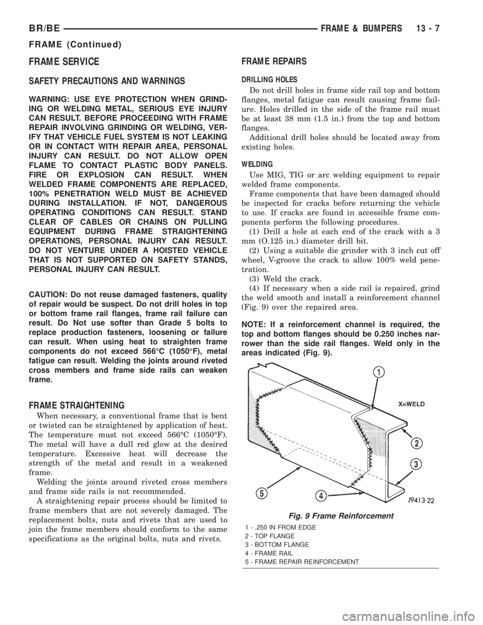
(4) If necessary when a side rail is repaired, grind
the weld smooth and install a reinforcement channel
(Fig. 9) over the repaired area.
NOTE: If a reinforcement channel is required, the
top and bottom flanges should be 0.250 inches nar-
rower than the side rail flanges. Weld only in the
areas indicated (Fig. 9).
Fig. 9 Frame Reinforcement
1 - .250 IN FROM EDGE
2 - TOP FLANGE
3 - BOTTOM FLANGE
4 - FRAME RAIL
5 - FRAME REPAIR REINFORCEMENT
BR/BEFRAME & BUMPERS 13 - 7
FRAME (Continued)
Page 1301 of 2255
FUEL DELIVERY - GASOLINE
DESCRIPTION - FUEL DELIVERY SYSTEM
The fuel delivery system consists of:
²the fuel pump module containing the electric
fuel pump, fuel filter/fuel pressure regulator, rollover
valve (certain modules), fuel gauge sending unit (fuel
level sensor) and a separate fuel filter located at bot-
tom of pump module
²fuel tubes/lines/hoses
²quick-connect fittings
²fuel injector rail
²fuel injectors
²fuel tank
²fuel tank filler/vent tube assembly
²fuel tank filler tube cap
²accelerator pedal
²throttle cable
OPERATION - FUEL DELIVERY SYSTEM
Fuel is returned through the fuel pump module
and back into the fuel tank through the fuel filter/
fuel pressure regulator. A separate fuel return line
from the engine to the tank is not used with any gas-
oline powered engine.
The fuel tank assembly consists of: the fuel tank,
fuel pump module assembly, fuel pump module lock-
nut/gasket and fuel tank check valve(s) (refer to 25,
Emission Control System for Fuel Tank Check Valve
information).
A fuel filler/vent tube assembly using a pressure/
vacuum, 1/4 turn fuel filler cap is used. The fuel
filler tube contains a flap door located below the fuel
fill cap.
Also to be considered part of the fuel system is the
evaporation control system. This is designed to
reduce the emission of fuel vapors into the atmo-
sphere. The description and function of the Evapora-
tive Control System is found in 25, Emission Control
Systems.
Both fuel filters (at bottom of fuel pump module
and within fuel pressure regulator) are designed for
extended service. They do not require normal sched-
uled maintenance. Filters should only be replaced if
a diagnostic procedure indicates to do so.
DIAGNOSIS AND TESTING - FUEL PRESSURE
LEAK DOWN TEST
Use this test in conjunction with the Fuel Pump
Pressure Test and Fuel Pump Capacity Test.
Check Valve Operation:The electric fuel pump
outlet contains a one-way check valve to prevent fuel
flow back into the tank and to maintain fuel supply
line pressure (engine warm) when pump is not oper-
ational. It is also used to keep the fuel supply linefull of gasoline when pump is not operational. After
the vehicle has cooled down, fuel pressure may drop
to 0 psi (cold fluid contracts), but liquid gasoline will
remain in fuel supply line between the check valve
and fuel injectors.Fuel pressure that has
dropped to 0 psi on a cooled down vehicle
(engine off) is a normal condition.When the elec-
tric fuel pump is activated, fuel pressure should
immediately(1±2 seconds) rise to specification.
Abnormally long periods of cranking to restart a
hotengine that has been shut down for a short
period of time may be caused by:
²Fuel pressure bleeding past a fuel injector(s).
²Fuel pressure bleeding past the check valve in
the fuel pump module.
(1) Disconnect the fuel inlet line at fuel rail. Refer
to Fuel Tubes/Lines/Hoses and Clamps for proce-
dures. On some engines, air cleaner housing removal
may be necessary before fuel line disconnection.
(2) Obtain correct Fuel Line Pressure Test Adapter
Tool Hose. Tool number 6539 is used for 5/16º fuel
lines and tool number 6631 is used for 3/8º fuel lines.
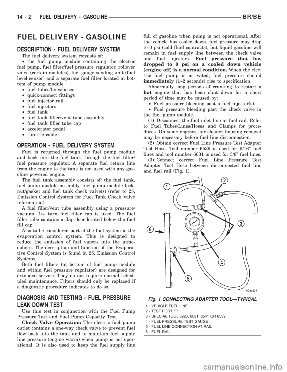
(3) Connect correct Fuel Line Pressure Test
Adapter Tool Hose between disconnected fuel line
and fuel rail (Fig. 1).
Fig. 1 CONNECTING ADAPTER TOOLÐTYPICAL
1 - VEHICLE FUEL LINE
2 - TEST PORT ªTº
3 - SPECIAL TOOL 6923, 6631, 6541 OR 6539
4 - FUEL PRESSURE TEST GAUGE
5 - FUEL LINE CONNECTION AT RAIL
6 - FUEL RAIL
14 - 2 FUEL DELIVERY - GASOLINEBR/BE
Page 1308 of 2255
FUEL PUMP
DESCRIPTION
The electric fuel pump is located inside of the fuel
pump module. A 12 volt, permanent magnet, electric
motor powers the fuel pump. The electric fuel pump
is not a separate, serviceable component.
OPERATION
Voltage to operate the electric pump is supplied
through the fuel pump relay.
Fuel is drawn in through a filter at the bottom of
the module and pushed through the electric motor
gearset to the pump outlet.
Check Valve Operation:The pump outlet con-
tains a one-way check valve to prevent fuel flow back
into the tank and to maintain fuel supply line pres-
sure (engine warm) when pump is not operational. It
is also used to keep the fuel supply line full of gaso-
line when pump is not operational. After the vehicle
has cooled down, fuel pressure may drop to 0 psi
(cold fluid contracts), but liquid gasoline will remain
in fuel supply line between the check valve and fuel
injectors.Fuel pressure that has dropped to 0
psi on a cooled down vehicle (engine off) is a
normal condition.Refer to the Fuel Pressure Leak
Down Test for more information.
The electric fuel pump is not a separate, service-
able component.
DIAGNOSIS AND TESTING
DIAGNOSIS AND TESTING - FUEL PUMP
CAPACITY TEST
Before performing this test, verify fuel pump
pressure. Refer to Fuel Pump Pressure Test.
Use this test in conjunction with the Fuel Pres-
sure Leak Down Test.
(1) Release fuel system pressure. Refer to Fuel
Pressure Release Procedure.
(2) Disconnect fuel supply line at fuel rail. Refer to
Quick-Connect Fittings. Some engines may require
air cleaner housing removal before line disconnection.
(3) Obtain correct Fuel Line Pressure Test Adapter
Tool Hose. Tool number 6539 is used for 5/16º fuel
lines and tool number 6631 is used for 3/8º fuel lines.
(4) Connect correct Fuel Line Pressure Test
Adapter Tool Hose into disconnected fuel supply line.
Insert other end of Adaptor Tool Hose into a gradu-
ated container.
(5) Remove fuel fill cap.
(6) To activate fuel pump and pressurize system,
obtain DRBtscan tool and actuate ASD Fuel System
Test.(7) A good fuel pump will deliver at least 1/4 liter
of fuel in 7 seconds. Do not operate fuel pump for
longer than 7 seconds with fuel line disconnected as
fuel pump module reservoir may run empty.
(a) If capacity is lower than specification, but
fuel pump can be heard operating through fuel fill
cap opening, check for a kinked/damaged fuel sup-
ply line somewhere between fuel rail and fuel
pump module.
(b) If line is not kinked/damaged, and fuel pres-
sure is OK, but capacity is low, replace fuel filter/
fuel pressure regulator. The filter/regulator may be
serviced separately on certain applications. Refer
to Fuel Filter/Fuel Pressure Regulator Removal/In-
stallation for additional information.
(c) If both fuel pressure and capacity are low,
replace fuel pump module assembly. Refer to Fuel
Pump Module Removal/Installation.
DIAGNOSIS AND TESTING - FUEL PUMP
PRESSURE TEST
Use this test in conjunction with the Fuel Pump
Capacity Test, Fuel Pressure Leak Down Test and
Fuel Pump Amperage Test found elsewhere in this
group.
Check Valve Operation:The electric fuel pump
outlet contains a one-way check valve to prevent fuel
flow back into the tank and to maintain fuel supply
line pressure (engine warm) when pump is not oper-
ational. It is also used to keep the fuel supply line
full of gasoline when pump is not operational. After
the vehicle has cooled down, fuel pressure may drop
to 0 psi (cold fluid contracts), but liquid gasoline will
remain in fuel supply line between the check valve
and fuel injectors.Fuel pressure that has
dropped to 0 psi on a cooled down vehicle
(engine off) is a normal condition.When the elec-
tric fuel pump is activated, fuel pressure should
immediately(1±2 seconds) rise to specification.
All fuel systems are equipped with a fuel tank
module mounted, combination fuel filter/fuel pressure
regulator. The fuel pressure regulator is not con-
trolled by engine vacuum.
WARNING: THE FUEL SYSTEM IS UNDER CON-
STANT FUEL PRESSURE EVEN WITH THE ENGINE
OFF. BEFORE DISCONNECTING FUEL LINE AT
FUEL RAIL, THIS PRESSURE MUST BE RELEASED.
REFER TO THE FUEL SYSTEM PRESSURE
RELEASE PROCEDURE.
(1) Remove protective cap at fuel rail test port.
Connect the 0±414 kPa (0-60 psi) fuel pressure gauge
(from gauge set 5069) to test port pressure fitting on
fuel rail (Fig. 11).The DRBtIII Scan Tool along
with the PEP module, the 500 psi pressure
BR/BEFUEL DELIVERY - GASOLINE 14 - 9
Page 1314 of 2255
The fuel rail is not repairable.
CAUTION: The left and right sections of the fuel rail
are connected with a flexible connecting hose. Do
not attempt to separate the rail halves at this con-
necting hose. Due to the design of this connecting
hose, it does not use any clamps. Never attempt to
install a clamping device of any kind to the hose.
When removing the fuel rail assembly for any rea-
son, be careful not to bend or kink the connecting
hose.
OPERATION - 8.0L
High pressure from the fuel pump is routed to the
fuel rail. The fuel rail then supplies the necessary
fuel to each individual fuel injector.
A fuel pressure test port is located on the fuel rail.
A quick-connect fitting with a safety latch clip is
used to attach the fuel line to the fuel rail.
The fuel rail is not repairable.
REMOVAL
REMOVAL - 5.9L
WARNING: THE FUEL SYSTEM IS UNDER A CON-
STANT PRESSURE (EVEN WITH ENGINE TURNED
OFF). BEFORE SERVICING FUEL RAIL ASSEMBLY,
FUEL SYSTEM PRESSURE MUST BE RELEASED.
To release fuel pressure, refer to Fuel System Pres-
sure Release Procedure found in this group.
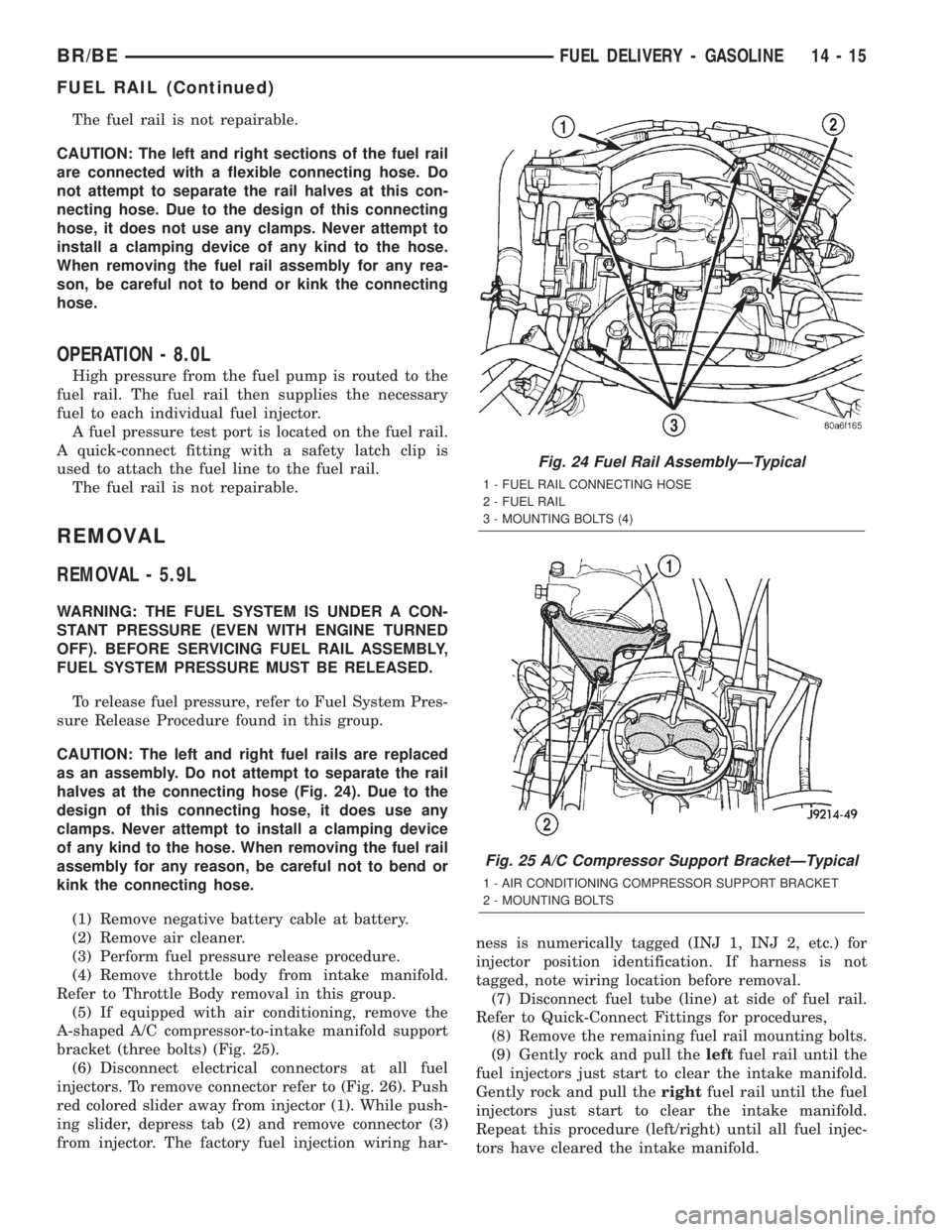
CAUTION: The left and right fuel rails are replaced
as an assembly. Do not attempt to separate the rail
halves at the connecting hose (Fig. 24). Due to the
design of this connecting hose, it does use any
clamps. Never attempt to install a clamping device
of any kind to the hose. When removing the fuel rail
assembly for any reason, be careful not to bend or
kink the connecting hose.
(1) Remove negative battery cable at battery.
(2) Remove air cleaner.
(3) Perform fuel pressure release procedure.
(4) Remove throttle body from intake manifold.
Refer to Throttle Body removal in this group.
(5) If equipped with air conditioning, remove the
A-shaped A/C compressor-to-intake manifold support
bracket (three bolts) (Fig. 25).
(6) Disconnect electrical connectors at all fuel
injectors. To remove connector refer to (Fig. 26). Push
red colored slider away from injector (1). While push-
ing slider, depress tab (2) and remove connector (3)
from injector. The factory fuel injection wiring har-ness is numerically tagged (INJ 1, INJ 2, etc.) for
injector position identification. If harness is not
tagged, note wiring location before removal.
(7) Disconnect fuel tube (line) at side of fuel rail.
Refer to Quick-Connect Fittings for procedures,
(8) Remove the remaining fuel rail mounting bolts.
(9) Gently rock and pull theleftfuel rail until the
fuel injectors just start to clear the intake manifold.
Gently rock and pull therightfuel rail until the fuel
injectors just start to clear the intake manifold.
Repeat this procedure (left/right) until all fuel injec-
tors have cleared the intake manifold.
Fig. 24 Fuel Rail AssemblyÐTypical
1 - FUEL RAIL CONNECTING HOSE
2 - FUEL RAIL
3 - MOUNTING BOLTS (4)
Fig. 25 A/C Compressor Support BracketÐTypical
1 - AIR CONDITIONING COMPRESSOR SUPPORT BRACKET
2 - MOUNTING BOLTS
BR/BEFUEL DELIVERY - GASOLINE 14 - 15
FUEL RAIL (Continued)