2001 YAMAHA XVZ1300TF ECU
[x] Cancel search: ECUPage 30 of 132

INSTRUMENT AND CONTROL FUNCTIONS
3-15
3
EAU01781
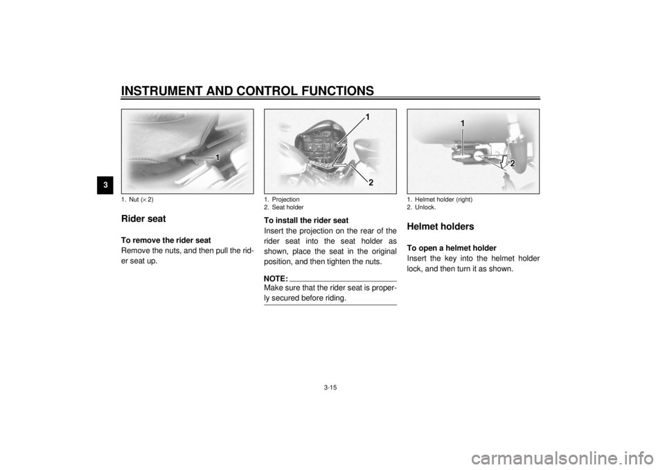
Rider seat To remove the rider seat
Remove the nuts, and then pull the rid-
er seat up.To install the rider seat
Insert the projection on the rear of the
rider seat into the seat holder as
shown, place the seat in the original
position, and then tighten the nuts.
NOTE:@ Make sure that the rider seat is proper-
ly secured before riding. @
EAU01782
Helmet holders To open a helmet holder
Insert the key into the helmet holder
lock, and then turn it as shown.
1. Nut (´ 2)
1. Projection
2. Seat holder
1. Helmet holder (right)
2. Unlock.
E_5jc.book Page 15 Monday, January 22, 2001 12:12 PM
Page 31 of 132

INSTRUMENT AND CONTROL FUNCTIONS
3-16
3
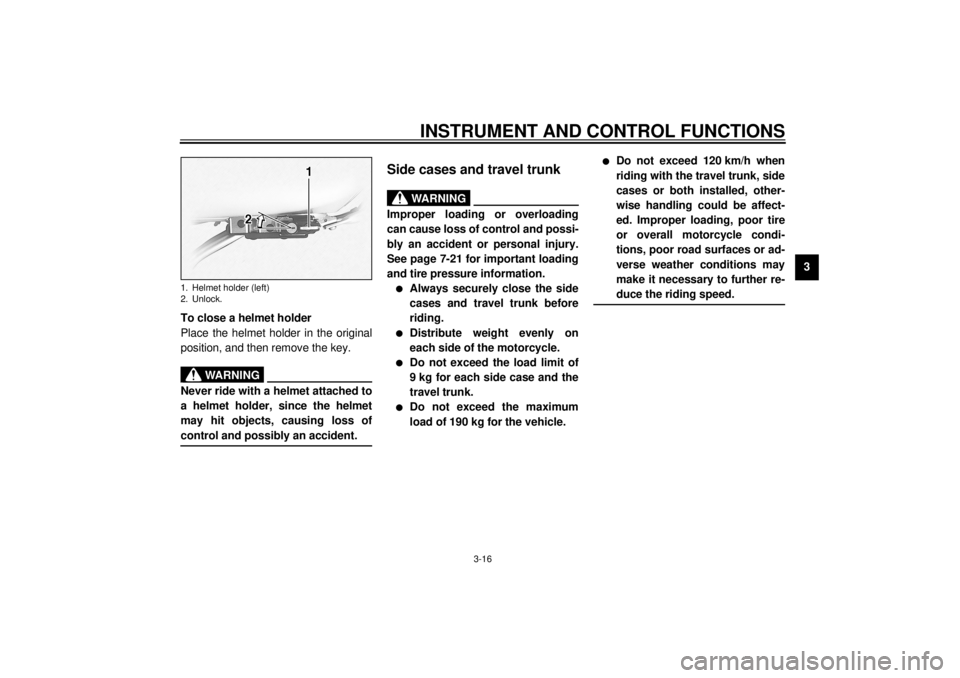
To close a helmet holder
Place the helmet holder in the original
position, and then remove the key.
EWA00015
WARNING
@ Never ride with a helmet attached to
a helmet holder, since the helmet
may hit objects, causing loss of
control and possibly an accident. @
EAU01866*
Side cases and travel trunk
EWA00021*
WARNING
@ Improper loading or overloading
can cause loss of control and possi-
bly an accident or personal injury.
See page 7-21 for important loading
and tire pressure information.l
Always securely close the side
cases and travel trunk before
riding.
l
Distribute weight evenly on
each side of the motorcycle.
l
Do not exceed the load limit of
9 kg for each side case and the
travel trunk.
l
Do not exceed the maximum
load of 190 kg for the vehicle.
l
Do not exceed 120 km/h when
riding with the travel trunk, side
cases or both installed, other-
wise handling could be affect-
ed. Improper loading, poor tire
or overall motorcycle condi-
tions, poor road surfaces or ad-
verse weather conditions may
make it necessary to further re-
duce the riding speed.
@
1. Helmet holder (left)
2. Unlock.
E_5jc.book Page 16 Monday, January 22, 2001 12:12 PM
Page 34 of 132

INSTRUMENT AND CONTROL FUNCTIONS
3-19
3
EAU03719
Adjusting the front fork This front fork is equipped with air
valves for adjusting the spring rate.
EW000035
WARNING
_ Always adjust both fork legs equal-
ly, otherwise poor handling and loss
of stability may result. _Adjust the spring rate as follows.
1. Place the motorcycle on the side-
stand.NOTE:_ When checking and adjusting the air
pressure, there should be no weight on
the motorcycle. _
2. Remove the air valve cap from
each fork leg.
3. Check the air pressure in each
fork leg with the air pressure
gauge included in the owner’s tool
kit.
4. To increase the spring rate and
thereby harden the suspension,
increase the air pressure with an
air pump. To decrease the spring
rate and thereby soften the sus-
pension, decrease the air pres-
sure by pushing each valve stem
down.
EC000012
CAUTION:_ Never exceed the maximum air pres-
sure, otherwise the front fork oil
seals may become damaged. _5. Securely install the air valve caps.
1. Front fork air valve cap
Spring rate:
Minimum (soft):
Air pressure =
0 kPa (0 kgf/cm
2, 0 bar)
Standard:
Air pressure =
0 kPa (0 kgf/cm2, 0 bar)
Maximum (hard):
Air pressure =
50 kPa (0.5 kgf/cm
2, 0.5 bar)
E_5jc.book Page 19 Monday, January 22, 2001 12:12 PM
Page 36 of 132

INSTRUMENT AND CONTROL FUNCTIONS
3-21
3
ECA00050
CAUTION:_ Never exceed the maximum air pres-
sure, otherwise the oil seal may be-
come damaged. _5. Securely install the air valve cap.
EAU00330
Sidestand The sidestand is located on the left side
of the frame. Raise the sidestand or
lower it with your foot while holding the
motorcycle upright.NOTE:@ The built-in sidestand switch is part of
the ignition circuit cut-off system, which
cuts the ignition in certain situations.
(See further down for an explanation of
the ignition circuit cut-off system.) @
EW000044
WARNING
@ The motorcycle must not be ridden
with the sidestand down, or if the
sidestand cannot be properly
moved up (or does not stay up), oth-
erwise the sidestand could contact
the ground and distract the opera-
tor, resulting in a possible loss of
control. Yamaha’s ignition circuit
cut-off system has been designed to
assist the operator in fulfilling the
responsibility of raising the side-
stand before starting off. Therefore,
check this system regularly as de-
scribed below and have a Yamaha
dealer repair it if it does not function
properly. @
E_5jc.book Page 21 Monday, January 22, 2001 12:12 PM
Page 95 of 132

PERIODIC MAINTENANCE AND MINOR REPAIR
7-22
7
EWA00041
WARNING
_ Tire inflation pressure should be
checked and adjusted when the
temperature of the tire equals the
ambient air temperature. Tire infla-
tion pressure must be adjusted ac-
cording to total weight of cargo,
rider, passenger, and accessories
(cowling, side cases, etc.). _CE-21E
CE-07EEWA00042
WARNING
_ Proper loading of your motorcycle
is important for several characteris-
tics of your motorcycle, such as
handling, braking, performance and
safety. Do not carry loosely packed
items that can shift. Securely pack
your heaviest items close to the
center of the motorcycle, and dis-
tribute the weight evenly from side
to side. Properly adjust the suspen-
sion for your load, and check the
condition and pressure of your tires.
NEVER OVERLOAD YOUR MOTOR-
CYCLE. Make sure the total weight
of the cargo, rider, passenger, and
accessories (cowling, side cases,
etc. if approved for this model) does
not exceed the maximum load of the
motorcycle. Operation of an over-
loaded motorcycle could cause tire
damage, an accident, or even injury. _
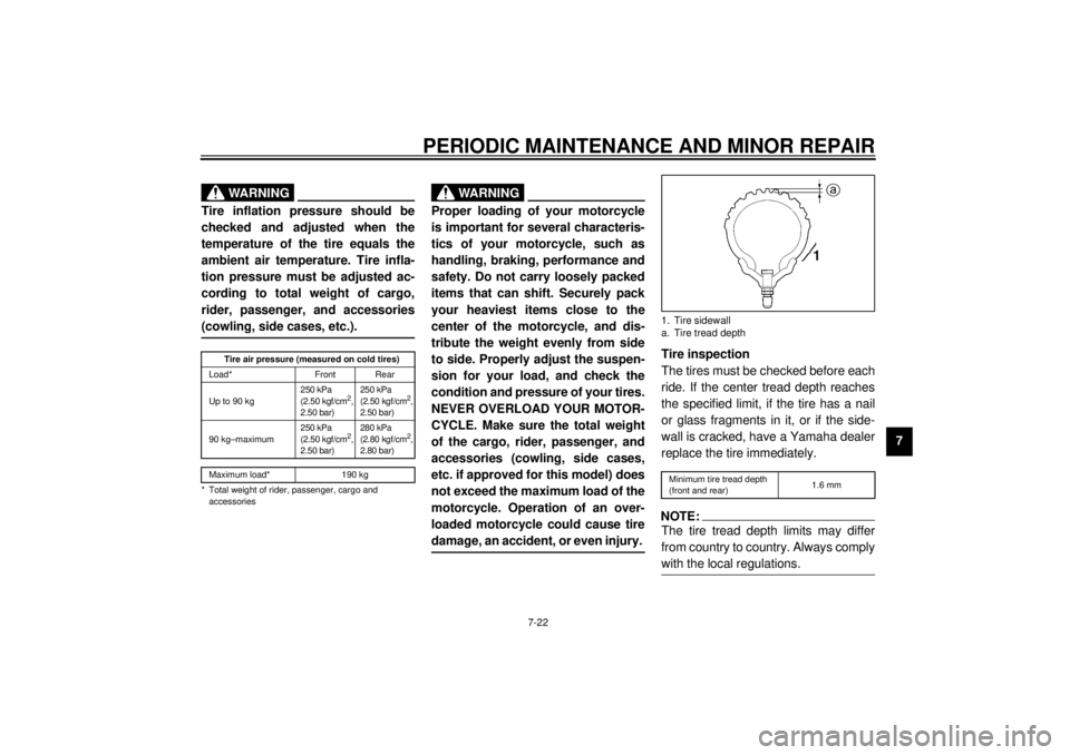
Tire inspection
The tires must be checked before each
ride. If the center tread depth reaches
the specified limit, if the tire has a nail
or glass fragments in it, or if the side-
wall is cracked, have a Yamaha dealer
replace the tire immediately.CE-08ENOTE:_ The tire tread depth limits may differ
from country to country. Always comply
with the local regulations. _
Tire air pressure (measured on cold tires)
Load* Front Rear
Up to 90 kg250 kPa
(2.50 kgf/cm
2,
2.50 bar)250 kPa
(2.50 kgf/cm
2,
2.50 bar)
90 kg–maximum250 kPa
(2.50 kgf/cm
2,
2.50 bar)280 kPa
(2.80 kgf/cm
2,
2.80 bar)
Maximum load* 190 kg
* Total weight of rider, passenger, cargo and
accessories
1. Tire sidewall
a. Tire tread depthMinimum tire tread depth
(front and rear)1.6 mm
E_5jc.book Page 22 Monday, January 22, 2001 12:12 PM
Page 96 of 132

PERIODIC MAINTENANCE AND MINOR REPAIR
7-23
7
EW000079
WARNING
_ l
Have a Yamaha dealer replace
excessively worn tires. Besides
being illegal, operating the
motorcycle with excessively
worn tires decreases riding sta-
bility and can lead to loss of
control.
l
The replacement of all wheel-
and brake-related parts, includ-
ing the tires, should be left to a
Yamaha dealer, who has the
necessary professional knowl-
edge and experience.
_
Tire information
This motorcycle is equipped with tube-
less tires, tire air valves and cast
wheels.
EW000132
WARNING
_ l
The front and rear tires should
be of the same make and de-
sign, otherwise the handling
characteristics of the motor-
cycle cannot be guaranteed.
l
After extensive tests, only the
tires listed below have been ap-
proved for this model by
Yamaha Motor Co., Ltd.
l
Always make sure that the valve
caps are securely installed to
prevent air pressure leakage.
l
Use only the tire valves and
valve cores listed below to
avoid tire deflation during a
ride.
_
1. Tire air valve
2. Tire air valve core
3. Tire air valve cap with seal
E_5jc.book Page 23 Monday, January 22, 2001 12:12 PM
Page 104 of 132

PERIODIC MAINTENANCE AND MINOR REPAIR
7-31
7
EAU02939
Checking the front fork The condition and operation of the front
fork must be checked as follows at the
intervals specified in the periodic main-
tenance and lubrication chart.
To check the condition
EW000115
WARNING
@ Securely support the motorcycle so
that there is no danger of it falling
over. @Check the inner tubes for scratches,
damage and excessive oil leakage.To check the operation
1. Place the motorcycle on a level
surface and hold it in an upright
position.
2. While applying the front brake,
push down hard on the handle-
bars several times to check if the
front fork compresses and re-
bounds smoothly.
EC000098
CAUTION:@ If any damage is found or the front
fork does not operate smoothly,
have a Yamaha dealer check or re-
pair it. @
EAU00794
Checking the steering Worn or loose steering bearings may
cause danger. Therefore, the operation
of the steering must be checked as fol-
lows at the intervals specified in the pe-
riodic maintenance and lubrication
chart.
1. Place a stand under the engine to
raise the front wheel off the
ground.
EW000115
WARNING
@ Securely support the motorcycle so
that there is no danger of it falling
over. @
E_5jc.book Page 31 Monday, January 22, 2001 12:12 PM
Page 108 of 132

PERIODIC MAINTENANCE AND MINOR REPAIR
7-35
73. Turn the key to “ON” and turn on
the electrical circuit in question to
check if the device operates.
4. If the fuse immediately blows
again, have a Yamaha dealer
check the electrical system.
EAU01802
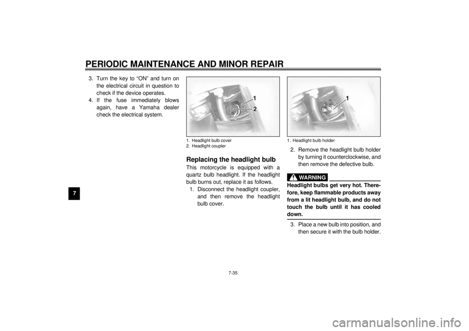
Replacing the headlight bulb This motorcycle is equipped with a
quartz bulb headlight. If the headlight
bulb burns out, replace it as follows.
1. Disconnect the headlight coupler,
and then remove the headlight
bulb cover.2. Remove the headlight bulb holder
by turning it counterclockwise, and
then remove the defective bulb.
EW000119
WARNING
@ Headlight bulbs get very hot. There-
fore, keep flammable products away
from a lit headlight bulb, and do not
touch the bulb until it has cooled
down. @3. Place a new bulb into position, and
then secure it with the bulb holder.
1. Headlight bulb cover
2. Headlight coupler
1. Headlight bulb holder
E_5jc.book Page 35 Monday, January 22, 2001 12:12 PM