Page 44 of 132

AUDIO SYSTEM
4-3
4
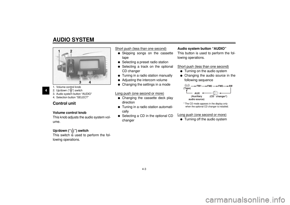
Control unit Volume control knob
This knob adjusts the audio system vol-
ume.
Up/down (“ ”) switch
This switch is used to perform the fol-
lowing operations.Short push (less than one second)
l
Skipping songs on the cassette
tape
l
Selecting a preset radio station
l
Selecting a track on the optional
CD changer
l
Tuning in a radio station manually
l
Adjusting the intercom volume
l
Changing the settings in a mode
Long push (one second or more)
l
Changing the cassette deck play
direction
l
Tuning in a radio station automati-
cally
l
Selecting a CD in the optional CD
changerAudio system button “AUDIO”
This button is used to perform the fol-
lowing operations.
Short push (less than one second)
l
Turning on the audio system
l
Changing the audio source in the
following sequence
Long push (one second or more)
l
Turning off the audio system
1. Volume control knob
2. Up/down (“ ”) switch
3. Audio system button “AUDIO”
4. Selection button “SELECT”
(Tape)FM1
FM2
FM3AM
AUX
(CD changer
*)
(Auxiliary
audio source)
* The CD mode appears in the display only
when the optional CD changer is installed.
E_5jc.book Page 3 Monday, January 22, 2001 12:12 PM
Page 45 of 132
AUDIO SYSTEM
4-4
4 Selection button “SELECT”
This button is used to perform the fol-
lowing operations.
Short push (less than two seconds)
l
Changing modes in the following
sequence
l
Programming preset radio stations
Long push (two seconds or more)
l
Selecting the preset radio station
programming mode
(Output)BASS TREBFAD
(Auto
volume)
(Intercom
volume)
Radio SP/HS
(Treble)
frequency(Fade )
1
2IC
AV
1
2This mode does not appear in the display when
the headsets are selected as the output.
This mode appears in the display only when one
of the radio frequency bands is selected as the au- dio source.
E_5jc.book Page 4 Monday, January 22, 2001 12:12 PM
Page 46 of 132

AUDIO SYSTEM
4-5
4
Making basic settings Turning on/off the audio system
To turn the power on1. Make sure that the key is in the
“ACC” or “ON” position.
2. Push the “AUDIO” button once for
less than one second.
To turn the power offPush the “AUDIO” button once for one
second or more.Adjusting the audio system volume
Turn the volume control knob until the
desired audio system volume is dis-
played (e.g., “Vo:10”). The audio sys-
tem volume can be set between “0”
and “30”. After the adjustment is made,
the audio system returns to normal op-
eration and the current audio mode ap-
pears in the display.
Making mode settings General procedure
The following setting procedure applies
to the audio system and optional CD
changer.NOTE:_ In order to make settings in any of the
audio system modes, make sure that
the audio system is selected. If neces-
sary, push the “AUDIO” button for less
than one second. _1. Push the “AUDIO” button for less
than one second.
2. Repeatedly push the “SELECT”
button for less than one second
until the desired mode appears in
the display. With each press of the
button, the mode changes in the
following sequence.
E_5jc.book Page 5 Monday, January 22, 2001 12:12 PM
Page 47 of 132

AUDIO SYSTEM
4-6
4
3. While the selected mode is dis-
played (for about five seconds),
repeatedly push either side of the
up/down switch for less than one
second until the desired setting is
displayed.Selecting the output (speakers or
headsets)
1. Repeatedly push the “SELECT”
button for less than one second
until either “SP” (speakers) or “HS”
and “ ” (headsets) appear in the
display.
2. Push either side of the up/down
switch for less than one second to
change the setting.
NOTE:_ The speakers and headsets cannot be
used at the same time. _
Adjusting the bass level
1. Repeatedly push the “SELECT”
button for less than one second
until “BASS” appears at the bot-
tom of the display.
2. Repeatedly push either side of the
up/down switch for less than one
second until the desired level is
displayed. The bass level can be
set between “-6” and “+6”.
(Output)BASS TREBFAD
(Auto
volume)
(Intercom
volume)
Radio SP/HS
(Treble)
frequency(Fade )
1
2IC
AV
1
2This mode does not appear in the display when
the headsets are selected as the output.
This mode appears in the display only when one
of the radio frequency bands is selected as the au- dio source.
E_5jc.book Page 6 Monday, January 22, 2001 12:12 PM
Page 54 of 132

AUDIO SYSTEM
4-13
4
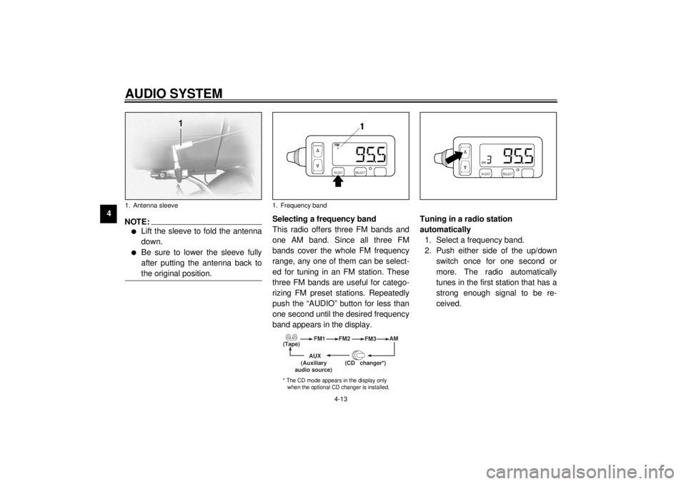
NOTE:_ l
Lift the sleeve to fold the antenna
down.
l
Be sure to lower the sleeve fully
after putting the antenna back to
the original position.
_
Selecting a frequency band
This radio offers three FM bands and
one AM band. Since all three FM
bands cover the whole FM frequency
range, any one of them can be select-
ed for tuning in an FM station. These
three FM bands are useful for catego-
rizing FM preset stations. Repeatedly
push the “AUDIO” button for less than
one second until the desired frequency
band appears in the display.Tuning in a radio station
automatically
1. Select a frequency band.
2. Push either side of the up/down
switch once for one second or
more. The radio automatically
tunes in the first station that has a
strong enough signal to be re-
ceived.
1. Antenna sleeve
1. Frequency band
(Tape)FM1
FM2
FM3AM
AUX
(CD changer
*)
(Auxiliary
audio source)
* The CD mode appears in the display only
when the optional CD changer is installed.
E_5jc.book Page 13 Monday, January 22, 2001 12:12 PM
Page 58 of 132

AUDIO SYSTEM
4-17
4
Optional CD changer
operation
WARNING
_ l
It is dangerous to operate the
CD changer while riding. Never
take your hands off the handle-
bars while riding.
l
Keep the volume at a low
enough level to be aware of traf-
fic conditions and ensure safe-
ty.
_An optional six-disc CD changer can be
mounted in the travel trunk. Ask a
Yamaha dealer to install the genuine
Clarion CDC635 model.Playing a CD
1. Insert up to six CDs into the CD
changer. Follow the manufactur-
er’s directions.
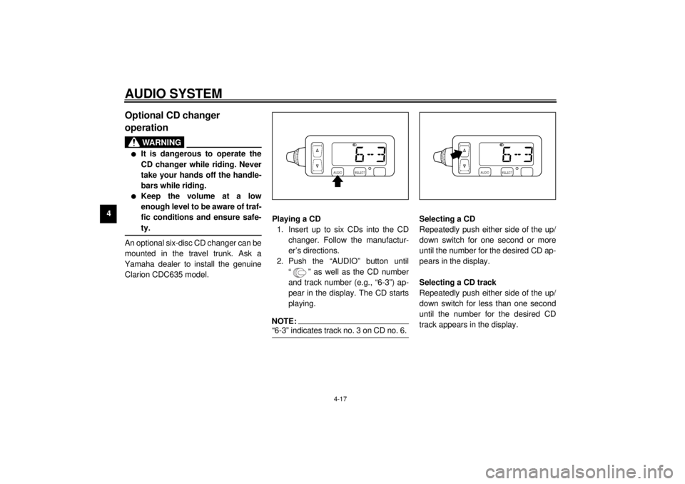
2. Push the “AUDIO” button until
“ ” as well as the CD number
and track number (e.g., “6-3”) ap-
pear in the display. The CD starts
playing.
NOTE:_ “6-3” indicates track no. 3 on CD no. 6. _
Selecting a CD
Repeatedly push either side of the up/
down switch for one second or more
until the number for the desired CD ap-
pears in the display.
Selecting a CD track
Repeatedly push either side of the up/
down switch for less than one second
until the number for the desired CD
track appears in the display.
E_5jc.book Page 17 Monday, January 22, 2001 12:12 PM
Page 98 of 132

PERIODIC MAINTENANCE AND MINOR REPAIR
7-25
7
EAU00695
Clutch lever free play Since this model is equipped with a hy-
draulic clutch, adjusting the clutch lever
free play is not needed. However, it is
necessary to check the clutch fluid lev-
el and check the hydraulic system for
leakage before each ride. If the clutch
lever free play does become exces-
sive, and shifting becomes rough or
clutch slippage occurs, causing poor
acceleration, there may be air in the
clutch system. If there is air in the hy-
draulic system, have a Yamaha dealer
bleed the system before operating the
motorcycle.
EAU00696
Adjusting the brake lever free
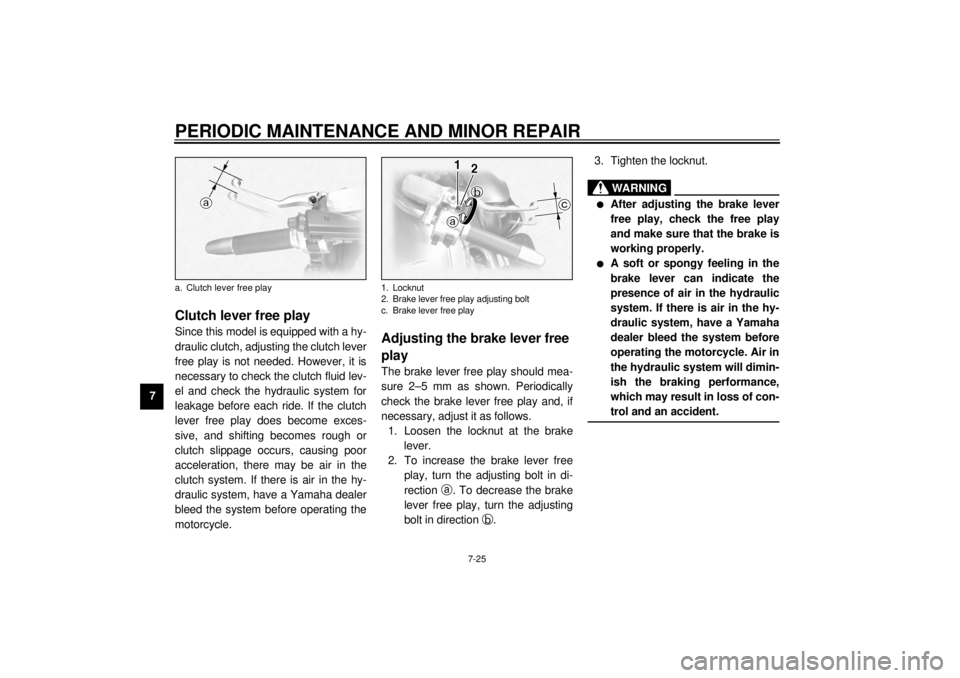
play The brake lever free play should mea-
sure 2–5 mm as shown. Periodically
check the brake lever free play and, if
necessary, adjust it as follows.
1. Loosen the locknut at the brake
lever.
2. To increase the brake lever free
play, turn the adjusting bolt in di-
rection
a. To decrease the brake
lever free play, turn the adjusting
bolt in direction
b.3. Tighten the locknut.
EW000099
WARNING
@ l
After adjusting the brake lever
free play, check the free play
and make sure that the brake is
working properly.
l
A soft or spongy feeling in the
brake lever can indicate the
presence of air in the hydraulic
system. If there is air in the hy-
draulic system, have a Yamaha
dealer bleed the system before
operating the motorcycle. Air in
the hydraulic system will dimin-
ish the braking performance,
which may result in loss of con-
trol and an accident.
@
a. Clutch lever free play
1. Locknut
2. Brake lever free play adjusting bolt
c. Brake lever free play
E_5jc.book Page 25 Monday, January 22, 2001 12:12 PM
Page 120 of 132

9-1
9
EAU01038
9-SPECIFICATIONSSpecifications CS-01E
Model XVZ1300TF
Dimensions
Overall length 2,705 mm
Overall width 900 mm
Overall height 1,565 mm (except for D)
1,380 mm (for D)
Seat height 750 mm
Wheelbase 1,705 mm
Minimum ground clearance 155 mm
Minimum turning radius 3,500 mm
Basic weight (with oil and full
fuel tank)
394 kg
Engine
Engine type Liquid-cooled 4-stroke, DOHC
Cylinder arrangement V-type, 4-cylinder
Displacement 1,294 cm
3
Bore ´ stroke 79 ´ 66 mm
Compression ratio 10:1
Starting system Electric starter
Lubrication system Wet sumpEngine oil
Ty p e
Recommended engine oil
classification API Service SE, SF, SG or
higher
Quantity
Without oil filter cartridge
replacement 3.5 L
With oil filter car tridge
replacement 3.7 L
Total amount (dry engine) 4.3 L
-20 -10 0
10 20 30
40
50 ˚C
SAE 10W-30
SAE 15W-40SAE 20W-40SAE 20W-50
SAE 10W-40
CAUTION:Be sure to use motor oils that do not contain anti-friction
modifiers. Passenger car motor oils (often labeled
“ENERGY CONSERVING II”) contain anti-friction additives
which will cause clutch and/or starter clutch slippage, result-
ing in reduced component life and poor engine performance.
E_5jc.book Page 1 Monday, January 22, 2001 12:12 PM