Page 274 of 4323

MONITOR STRATEGY
P0011VVT system advance (Bank 1)
RltdDTCP0012VVT system retard (Bank 1)Related DTCsP0021VVT system advance (Ba")
DI±80
± DIAGNOSTICSENGINE
274 Author�: Date�:
2005 SEQUOIA (RM1146U)
MONITOR STRATEGY
P0011VVT system advance (Bank 1)
RltdDTCP0012VVT system retard (Bank 1)Related DTCsP0021VVT system advance (Bank 2)
P0022VVT system retard (Bank 2)
Main sensors/componentsCamshaft position sensor
Required sensors/componentsRelated sensors/componentsEngine coolant temperature sensor,
Crankshaft position sensor
Frequency of operationOnce per drive cycle
Duration10 sec.
MIL operationP0011, P0021: Immediate
P0012, P0022: 2 driving cycles
Sequence of operationNone
TYPICAL ENABLING CONDITIONS
ItSpecificationItemMinimumMaximum
The monitor will run whenever these
DTCs are not presentSee page DI±18
Battery voltage11 V±
Throttle position learningCompleted
Engine RPM400 rpm4,000 rpm
Engine coolant temperature75�C (167�F)100�C (212�F)
TYPICAL MALFUNCTION THRESHOLDS
Detection CriteriaThreshold
Deviation of valve timingMore than 5�CA
OCV activation63 times or more
Response of valve timing1 sec./1�CA or more
WIRING DIAGRAM
Refer to DTCs P0010 on page DI±73.
INSPECTION PROCEDURE
HINT:
�Bank 1 refers to bank that includes cylinder No. 1.
�Bank 2 refers to bank that does not include cylinder No. 1.
�If DTC P0011, P0012 is displayed, check the bank 1 VVT system.
�If DTC P0021, P0022 is displayed, check the bank 2 VVT system.
�Read freeze frame data using the hand±held tester. Freeze frame data records the engine conditions
when a malfunction is detected. When troubleshooting, it is useful for determining whether the vehicle
was running or stopped, the engine was warmed up or not, the air±fuel ratio was lean or rich, etc. at
the time of the malfunction.
Page 275 of 4323

1 Check operation of OCV.
PREPARATION:
(a) Connect the hand±held tester to the DLC3.
(b) Start the engine and warm it up.
(c)")
± DIAGNOSTICSENGINE
DI±81
275 Author�: Date�:
2005 SEQUOIA (RM1146U)
1 Check operation of OCV.
PREPARATION:
(a) Connect the hand±held tester to the DLC3.
(b) Start the engine and warm it up.
(c) Turn the ignition switch to ON and turn the hand±held tester ON.
CHECK:
(a) Select the item: DIAGNOSIS / ENHANCED OBD II / ACTIVE TEST / VVT CTRL B1 or VVT CTRL B2.
(b) Using the hand±held tester, operate the OCV and check the engine speed.
OK:
Standard:
Tester OperationSpecified Condition
OCV is OFFNormal engine speed
OCV is ONRough idle or engine stall
OK VVT system is OK.*
*: DTC P0011, P0012, P0021 or P0022 is also output when a
foreign object is detected in some parts of the system in the en-
gine oil, and then the system returns to normal in a short time.
As ECM is controlled to eject a foreign object, there is no prob-
lem on the VVT. There is also no problem on the VVT as the oil
filter should catch the foreign object in the engine oil.
NG
2 Check valve timing (See page EM±23).
NG Adjust valve timing.
OK
Page 276 of 4323
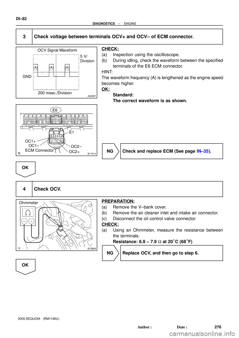
A02397
OCV Signal Waveform
200 msec./Division5 V/
Division
GND
(A) (A) (A)
B17414ECM ConnectorE6
OC1+
OC1±
OC2+OC2±
E1
B12806
Ohmmeter
DI±82
± DIAGNOSTICSENGINE
276 Author�: Date�:
2005 SEQUOIA (RM1146U)
3 Check voltage between terminals OCV+ and OCV± of ECM connector.
CHECK:
(a) Inspection using the oscilloscope.
(b) During idling, check the waveform between the specified
terminals of the E6 ECM connector.
HINT:
The waveform frequency (A) is lengthened as the engine speed
becomes higher.
OK:
Standard:
The correct waveform is as shown.
NG Check and replace ECM (See page IN±35).
OK
4 Check OCV.
PREPARATION:
(a) Remove the V±bank cover.
(b) Remove the air cleaner inlet and intake air connector.
(c) Disconnect the oil control valve connector.
CHECK:
(a) Using an Ohmmeter, measure the resistance between
the terminals.
Resistance: 6.9 ± 7.9 W at 20°C (68°F)
NG Replace OCV, and then go to step 6.
OK
Page 277 of 4323
A02852
A23658
± DIAGNOSTICSENGINE
DI±83
277 Author�: Date�:
2005 SEQUOIA (RM1146U)
5 Check VVT controller assembly.
PREPARATION:
(a) Remove the timing belt (See page EM±16).
(b) Remove the cylinder head cover.
(c) Remove the OCV (See page SF±46).
(d) Drain the oil in the VVT controller assembly
(See page EM±36).
CHECK:
Check whether the oil in VVT controller assembly is drained or
not.
OK:
Standard:
The oil in VVT controller assembly is drained.
NG Replace VVT controller assembly, and then go
to step 6.
OK
6 Check oil control valve filter.
PREPARATION:
(a) Remove the cylinder head cover.
(b) Remove the camshaft bearing cap and OCV filter.
CHECK:
Check that the filter is not clogged.
OK:
The filter is not clogged.
NG Repair or replace.
OK
Page 278 of 4323
DI±84
± DIAGNOSTICSENGINE
278 Author�: Date�:
2005 SEQUOIA (RM1146U)
7 Check whether or not DTC P0010, P0012, P0021 or P0022 is stored.
PREPARATION:
(a) Clear the DTC (See page DI±43).
(b) Perform simulation test.
CHECK:
Check whether or not DTC P0011, P0012, P0021 or P0022 is stored (See page DI±43).
OK:
Standard: DTC P0011, P0012, P0021 or P0022 is not stored.
OK VVT system is OK.*
*: DTC P0011, P0012, P0021 or P0022 is also output when a
foreign object is detected in some parts of the system in the en-
gine oil, and then the system returns to normal in a short time.
As ECM is controlled to eject a foreign object, there is no prob-
lem on the VVT. There is also no problem on the VVT as the oil
filter should catch the foreign object in the engine oil.
NG
Replace ECM.
Page 280 of 4323
DI±86
± DIAGNOSTICSENGINE
280 Author�: Date�:
2005 SEQUOIA (RM1146U)
MONITOR STRATEGY
RltdDTC
P0016Deviation in crankshaft position sensor signal
and camshaft position sensor signal (Bank 1)
Related DTCs
P0018Deviation in crankshaft position sensor signal
and camshaft position sensor signal (Bank 2)
Rid / tC k h ft iti C h ft itiRequired sensors/componentsCrankshaft position sensor, Camshaft position sensor
Frequency of operationOnce per drive cycle
Duration60 sec.
MIL operation2 drive cycles
Sequence of operationNone
TYPICAL ENABLING CONDITIONS
ItSpecificationItemMinimumMaximum
The monitor will run whenever this DTC is
not presentSee page DI±18
Engine RPM400 rpm1,400 rpm
TYPICAL MALFUNCTION THRESHOLDS
Detection CriteriaThreshold
Duration that either of the following conditions 1 or 2 is met18 sec. or more
1. VVT angle when camshaft is retarded maximumLess than 20�CA
2. VVT angle when camshaft is retarded maximumMore than 39�CA
Page 281 of 4323
A02961
V5
VVT Sensor (Bank 1)ECM
1
2R
G
Y
LVVL+
VVL±
VVR+
E5 18
19
19
18
VVR±
1
2E5
E4
E4 V6
VVT Sensor (Bank 2)
± DIAGNOSTICSENGINE
DI±87
281 Author�: Date�:
2005 SEQUOIA (RM1146U)
WIRING DIAGRAM
INSPECTION PROCEDURE
HINT:
�If DTC P0016 is displayed, check left bank VVT sensor.
�If DTC P0018 is displayed, check right bank VVT sensor.
�Read freeze frame data using hand±held tester or OBD II scan tool. Because freeze frame records
the engine conditions when the malfunction is detected. When troubleshooting, it is useful for deter-
mining whether the vehicle was running or stopped, the engine was warmed up or not, the air±fuel ratio
was lean or rich, etc. at the time of the malfunction.
1 Check valve timing (Check for loose and jumping teeth of timing belt) (See page
EM±16).
NG Adjust valve timing (Repair or replace timing
belt).
OK
Replace ECM (See page SF±80).
Page 282 of 4323
:
A/F Sensor A/F Relay
Heater
Sensor
A1A+ HA1A
Duty
Control ECM
From
Battery
A/F Heater
Fuse
A1A±
To EFI Relay DI±88
± DIAGNOSTICSENGINE
282 Auth")
A23512
Reference (Bank 1 Sensor 1 System Drawing):
A/F Sensor A/F Relay
Heater
Sensor
A1A+ HA1A
Duty
Control ECM
From
Battery
A/F Heater
Fuse
A1A±
To EFI Relay DI±88
± DIAGNOSTICSENGINE
282 Author�: Date�:
2005 SEQUOIA (RM1146U)
DTC P0031 Oxygen (A/F) Sensor Heater Control Circuit
Low (Bank 1 Sensor 1)
DTC P0032 Oxygen (A/F) Sensor Heater Control Circuit
High (Bank 1 Sensor 1)
DTC P0051 Oxygen (A/F) Sensor Heater Control Circuit
Low (Bank 2 Sensor 1)
DTC P0052 Oxygen (A/F) Sensor Heater Control Circuit
High (Bank 2 Sensor 1)
HINT:
Although each DTC title (DTC description) says ºoxygen sensorº, these DTCs are related to the ºA/F sensorº.
CIRCUIT DESCRIPTION
Refer to DTC P2195 on page DI±383.
HINT:
The ECM provides a pulse width modulated control circuit to adjust current through the heater. The A/F sen-
sor heater circuit uses a relay on the B+ side of the circuit.
DTC No.DTC Detection ConditionTrouble Area
P0031
P0051Heated current is 0.8 A or less when heater operates
(1 trip detection logic)�Open or short in heater circuit of A/F sensor
�A/F sensor heater
P0032
P0052When the heater operates, heated current exceeds 19.7 A
(1 trip detection logic)
A/F sensor heater
�A/F sensor heater relay
�ECM
DIDFP±01