Page 1306 of 4323
12345678
9 10111213141516
F19737
DLC3:
D6CANH
CANLCG
DI±1104
± DIAGNOSTICSCAN COMMUNICATION SYSTEM
1298 Author�: Date�:
2005 SEQUOIA (RM1146U)
7 Check CAN bus line for short to GND (Suspension control ECU sub bus line).
PREPARATION:
Disconnect the suspension control ECU connector (S25).
CHECK:
Measure the resistance according to the value(s) in the table
below.
OK:
Tester connectionConditionSpecified value
D6±4 (CG) ±
D6±6 (CANH)Ignition Switch OFF3 kW or higher
D6±4 (CG) ±
D6±14 (CANL)Ignition Switch OFF3 kW or higher
OK Replace suspension control ECU.
(See page SA±171)
NG
Repair or replace suspension control ECU
sub bus line or connector (CAN±H, CAN±L).
8 Connect the connector.
Reconnect the ECM main bus line connector (J53) to the junction connector.
NEXT
Page 1307 of 4323
12345678
9 10111213141516
F19737
DLC3:
D6CANH
CANLCG
± DIAGNOSTICSCAN COMMUNICATION SYSTEM
DI±1105
1299 Author�: Date�:
2005 SEQUOIA (RM1146U)
9 Check CAN bus line for short to GND (ECM main bus line).
PREPARATION:
Disconnect the ECM connector (E5).
CHECK:
Measure the resistance according to the value(s) in the table
below.
OK:
Tester connectionConditionSpecified value
D6±4 (CG) ±
D6±6 (CANH)Ignition Switch OFF3 kW or higher
D6±4 (CG) ±
D6±14 (CANL)Ignition Switch OFF3 kW or higher
OK Replace ECM (See page SF±80).
NG
Repair or replace ECM main bus line or con-
nector (CAN±H, CAN±L).
10 Connect the connector.
Reconnect the translate ECU main bus line connector (J55) to the junction connector.
NEXT
Page 1313 of 4323
12345678
9 10111213141516
F19737
DLC3:
D6CANH
CANL
BAT
± DIAGNOSTICSCAN COMMUNICATION SYSTEM
DI±1111
1305 Author�: Date�:
2005 SEQUOIA (RM1146U)
7 Check CAN bus line for short to +B (Suspension control ECU sub bus line).
PREPARATION:
Disconnect the suspension control ECU connector (S25).
CHECK:
Measure the resistance according to the value(s) in the table
below.
OK:
Tester connectionConditionSpecified value
D6±16 (BAT) ±
D6±6 (CANH)Ignition Switch OFF1 MW or higher
D6±16 (BAT) ±
D6±14 (CANL)Ignition Switch OFF1 MW or higher
OK Replace suspension control ECU
(See page SA±171).
NG
Repair or replace suspension control ECU
sub bus line or connector (CAN±H, CAN±L).
8 Connect the connector.
Reconnect the ECM main bus line connector (J53) to the junction connector.
NEXT
Page 1314 of 4323
12345678
9 10111213141516
F19737
DLC3:
D6CANH
CANL
BAT
DI±1112
± DIAGNOSTICSCAN COMMUNICATION SYSTEM
1306 Author�: Date�:
2005 SEQUOIA (RM1146U)
9 Check CAN bus line for short to +B (ECM main bus line).
PREPARATION:
Disconnect the ECM connector (E5).
CHECK:
Measure the resistance according to the value(s) in the table
below.
OK:
Tester connectionConditionSpecified value
D6±16 (BAT) ±
D6±6 (CANH)Ignition Switch OFF1 MW or higher
D6±16 (BAT) ±
D6±14 (CANL)Ignition Switch OFF1 MW or higher
OK Replace ECM (See page SF±80).
NG
Repair or replace ECM main bus line or con-
nector (CAN±H, CAN±L).
10 Connect the connector.
Reconnect the translate ECU main bus line connector (J55) to the junction connector.
NEXT
Page 1317 of 4323

Wire Harness View:
J56
G
WEarth Terminal
± DIAGNOSTICSCAN COMMUNICATION SYSTEM
DI±1115
1309 Author�: Date�:
2005 SEQUOIA (RM1146U)
INSPECTION PROCEDUR")
F19749
CAN J/C ºAº Side (w/ Earth Terminal)
Wire Harness View:
J56
G
WEarth Terminal
± DIAGNOSTICSCAN COMMUNICATION SYSTEM
DI±1115
1309 Author�: Date�:
2005 SEQUOIA (RM1146U)
INSPECTION PROCEDURE
1 Check for an open in one side of the CAN sub bus line (Suspension control ECU
sub bus line).
HINT:
For vehicles without an enhanced air suspension system, go to
step 3.
PREPARATION:
(a) Turn the ignition switch LOCK position.
(b) Disconnect the suspension control ECU sub bus line con-
nector (J56) from the CAN J/C.
NOTICE:
�Check the colors of the wire harnesses before dis-
connecting the connector.
�Before disconnecting the connector, make a note of
where it is connected.
�Reconnect the connector to its original position.
(c) Connect the hand±held tester to the DLC3 via CAN VIM.
(d) Turn the ignition switch ON.
CHECK:
Select ºBUS CHECKº on the hand±held tester display via the
CAN VIM (see page DI±1073).
RESULT:
AºREAR AIRSUSº does not appear
B2 or more ECUs and/or sensors do not appear
A Go to step 4.
B
2 Connect the connector.
(a) Turn the ignition switch LOCK position.
(b) Reconnect the suspension control ECU sub bus line connector (J56) to the CAN J/C.
NEXT
Page 1318 of 4323
DI±1116
± DIAGNOSTICSCAN COMMUNICATION SYSTEM
1310 Author�: Date�:
2005 SEQUOIA (RM1146U)
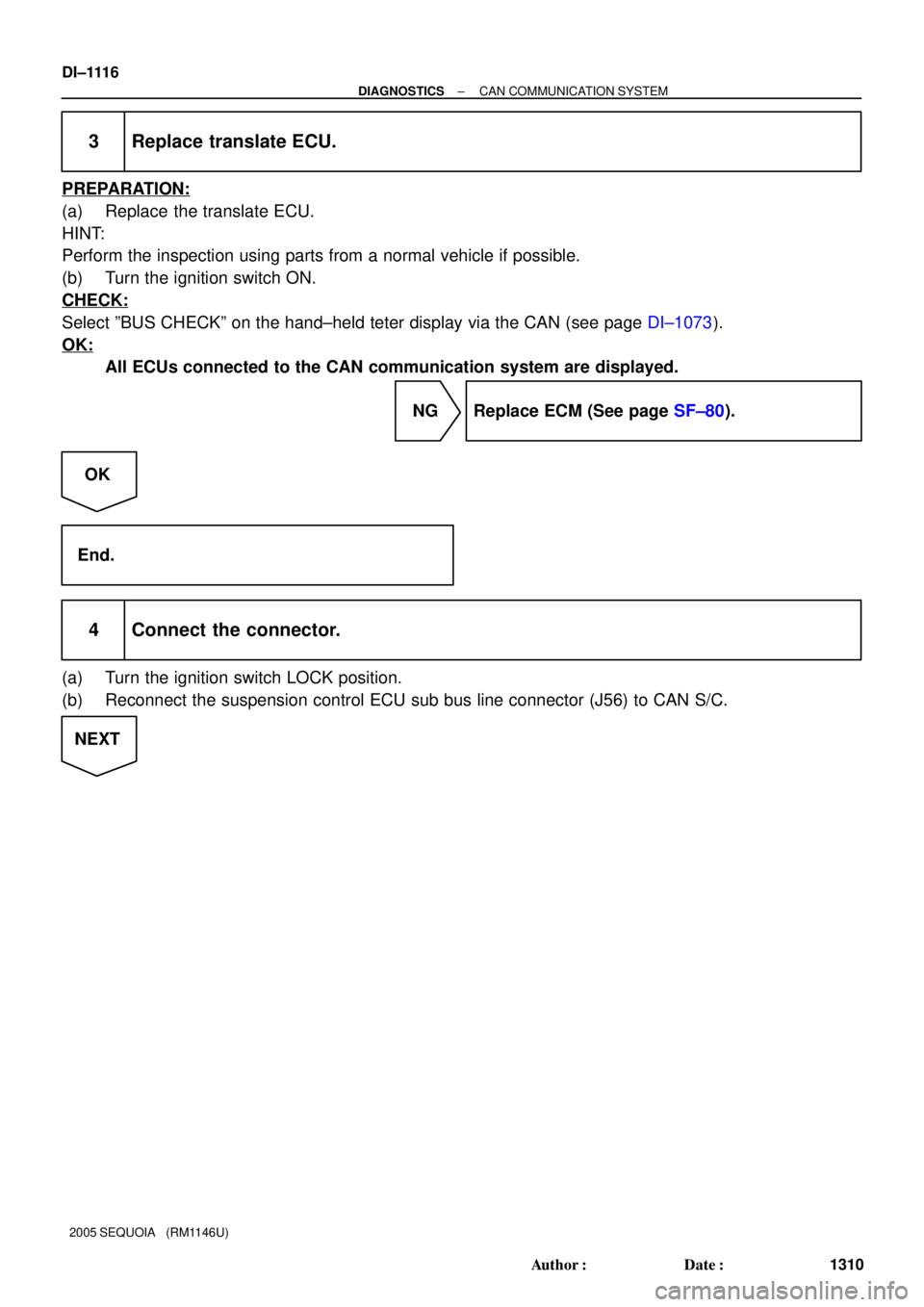
3 Replace translate ECU.
PREPARATION:
(a) Replace the translate ECU.
HINT:
Perform the inspection using parts from a normal vehicle if possible.
(b) Turn the ignition switch ON.
CHECK:
Select ºBUS CHECKº on the hand±held teter display via the CAN (see page DI±1073).
OK:
All ECUs connected to the CAN communication system are displayed.
NG Replace ECM (See page SF±80).
OK
End.
4 Connect the connector.
(a) Turn the ignition switch LOCK position.
(b) Reconnect the suspension control ECU sub bus line connector (J56) to CAN S/C.
NEXT
Page 1319 of 4323
F16805
Suspension Control ECU
Wire Harness View:
CANH
CANLS25
± DIAGNOSTICSCAN COMMUNICATION SYSTEM
DI±1117
1311 Author�: Date�:
2005 SEQUOIA (RM1146U)
5 Check for an open in one side of the CAN sub bus line (Suspension control ECU
sub bus line).
PREPARATION:
Disconnect the connector (S25) from the suspension control
ECU.
CHECK:
Measure the resistance according to the value(s) in the table
below.
OK:
Tester connectionConditionSpecified value
S25±29 (CANH) ±
S25±28 (CANL)Ignition Switch OFF54 to 69 W
NG Repair or replace suspension control ECU sub
bus line or connector (CAN±H, CAN±L).
OK
Replace suspension control ECU
(See page SA±171).
Page 1320 of 4323

SUPPLEMENTAL RESTRAINT SYSTEM
PRECAUTION
NOTICE:
When disconnecting the battery terminal, i")
DICY7±02
DI±1118
± DIAGNOSTICSSUPPLEMENTAL RESTRAINT SYSTEM
1312 Author�: Date�:
2005 SEQUOIA (RM1146U)
SUPPLEMENTAL RESTRAINT SYSTEM
PRECAUTION
NOTICE:
When disconnecting the battery terminal, initialize the following system after the terminal is recon-
nected.
System NameSee Page
Back Door Power Window Control SystemBE±77
1. HANDLING PRECAUTIONS FOR AIRBAG SENSOR
HINT:
In this section, the airbag sensor assembly, front airbag sensor LH, front airbag sensor RH, side airbag sen-
sor assembly LH, side airbag sensor assembly RH, curtain shield airbag sensor assembly LH, curtain shield
airbag sensor assembly RH and seat position airbag sensor assembly are collectively referred to as the air-
bag sensor.
(a) Before starting the following operations, wait at least 90 seconds after disconnecting the negative (±)
terminal of the battery:
(1) Replacement of the airbag sensor.
(2) Adjustment of the front/rear doors of the vehicle equipped with the side airbag and curtain shield
airbag (fitting adjustment).
(b) When connecting or disconnecting the airbag sensor connector, ensure that all of the sensors are
installed in the vehicle.
(c) Do not use an airbag sensor which has been dropped during the operation or transportation.
(d) Do not disassemble the airbag sensor.
2. INSPECTION PROCEDURE FOR VEHICLE INVOLVED IN ACCIDENT
(a) When the airbag has not deployed, confirm the DTC by checking the SRS warning light. If there is any
malfunction in the SRS airbag system, perform troubleshooting.
(b) When any of the airbags have deployed, replace the airbag sensor and check the installation condition.
(c) Perform the zero point calibration and sensitivity check under the condition is listed below (see page
DI±1128).
�The occupant classification ECU is replaced.
�Accessories (seatback tray, seat cover, etc.) are installed.
�The passenger seat removed from the vehicle.
�The passenger airbag ON/OFF indicator (ºOFFº) comes on when the passenger seat is not occu-
pied.
�The vehicle is brought to the workshop for repair due to an accident or a collision.
NOTICE:
When an accident vehicle is brought into the workshop for repair, check the flatness of the body side
that is installed on the passenger seat. If the flatness is not within ± 3.0 mm (0.118 in.), repair it to
the specified range (within ± 3.0 mm (0.118 in.)).