Page 1263 of 4323
F17798
Repair Wire
± DIAGNOSTICSCAN COMMUNICATION SYSTEM
DI±1061
1255 Author�: Date�:
2005 SEQUOIA (RM1146U)
(b) If it is impossible to check continuity from the rear of the
connector, then use a repair wire to check the connector.
3. PRECAUTION FOR DISCONNECTING THE BATTERY CABLE
NOTICE:
When disconnecting the battery terminal, initialize the following system after the terminal is recon-
nected.
System NameSee Page
Back Door Power Window Control SystemBE±77
Page 1266 of 4323

SYSTEM DESCRIPTION
1. BRIEF DESCRIPTION
(a) The CAN (Controller Area Network) is a serial data c")
DIDI0±01
DI±1064
± DIAGNOSTICSCAN COMMUNICATION SYSTEM
1258 Author�: Date�:
2005 SEQUOIA (RM1146U)
SYSTEM DESCRIPTION
1. BRIEF DESCRIPTION
(a) The CAN (Controller Area Network) is a serial data communication system for real time application.
It is an in±vehicle multiplex communication system that has a high communication speed (500 kbps)
and the function to detect malfunctions.
(b) By pairing the CANH and CANL bus lines, the CAN performs communication based on differential volt-
age.
(c) Many ECUs (sensors) installed in the vehicle operate by sharing information and communicating with
each other.
(d) The CAN has two resistors of 120 W which are necessary to communicate with the main bus line.
2. DEFINITION OF TERMS
(a) Main bus line
(1) The main bus line is a wire harness between the two terminus circuits on the bus (communication
line). This is the main bus in the CAN communication system.
(b) Sub bus line
(1) The sub bus line is a wire harness that diverges from the main bus line to the ECU.
3. ECUs THAT COMMUNICATE THROUGH CAN COMMUNICATION SYSTEM
(a) Translate ECU
(b) Suspension Control ECU
(c) ECM
4. DIAGNOSTIC CODE FOR CAN COMMUNICATION SYSTEM
DTCs for the CAN communication system are as follows:
U0100/65, U0122/67, U0132/72, 65, 94.
HINT:
If C1201/51, C1202/52 or C1203/53 is output from skid control ECU, perform troubleshooting of each diag-
nosis code (see page DI±921).
5. REMARK FOR TROUBLESHOOTING
(a) Trouble in the CAN bus (communication line) can be checked from the DLC3 (except when there is
a wire break in lines other than the sub bus line of the DLC3).
NOTICE:
Do not insert the tester directly into the DLC3 connector. Be sure to use a service wire.
(b) The CAN communication system cannot detect trouble in the sub bus line of the DLC3 even though
the DLC3 is also connected to the CAN communication system.
6. HOW TO DISTINGUISH THE CAN J/C CONNECTOR
In the CAN communication system, all connectors connected to the CAN J/C are the same shape. The con-
nectors connected to the CAN J/C can be distinguished by the colors of the bus lines.
HINT:
See ºTERMINALS OF ECUº (see page DI±1068) for bus line colors.
Page 1267 of 4323

DIDI1±01
END
P. DI±911, DI±723
Confirmation Test
Items inside are titles of pages in this manual,
with the page number in the bottom portion. See the
pages listed for detailed explanations.
DTC Combination Table
Vehicle Brought to Workshop
Check and Clear DTCs
P. DI±1067
All ECUs connected to the CAN communication system are displayed
An ECU not connected to the CAN communication system is displayed
A few ECUs not connected to the CAN communication system are displayed Check Using Hand±held Tester via CAN VIM
Select ºBUS CHECKº (see page DI±1073)
P. DI±1076
Check CAN Bus Line
Result Perform troubleshooting in accordance with the procedures on the following page.
A
B
C
Check for an open in one side of the CAN sub±bus line
P. DI±1114 P. DI±1067 Communication Stop Mode TableABC
Identification of
Problem
Repair or Replace
ENDConfirmation Test
P. DI±1086, DI±1092,
DI±1100, DI±1107 Circuit Inspection
Identification of
Problem
OKNG
P. DI±1079, DI±1081,
DI±1083Circuit Inspection
Repair or Replace
± DIAGNOSTICSCAN COMMUNICATION SYSTEM
DI±1065
1259 Author�: Date�:
2005 SEQUOIA (RM1146U)
HOW TO PROCEED WITH TROUBLESHOOTING
NOTICE:
�DTCs for the CAN communication system are as follows:
U0100/65, U0122/67, U0132/72, 65, 94.
�Refer to troubleshooting of each system if DTCs regarding the CAN communication system are
not output.
Page 1269 of 4323

Skid Control
ECU
Translate ECU
Suspen")
DIDI3±01
DTCTrouble Mode
Output fromOutput DTCECM
Communication
Stop ModeTranslate ECU
Communication
Stop ModeSuspension Control
ECU Communication
Stop Mode (*1)
Skid Control
ECU
Translate ECU
Suspension
Control
ECU (*1)
See pageU0100/65
65
94
U0100/65
U0122/67
U0132/71�
±
±±± �
��
�
�±
±
�
�
� �
DI±1079
DI±1081 DI±1083� �
± DIAGNOSTICSCAN COMMUNICATION SYSTEM
DI±1067
1261 Author�: Date�:
2005 SEQUOIA (RM1146U)
PROBLEM SYMPTOMS TABLE
1. COMMUNICATION STOP MODE TABLE
(a) Complete ºCheck CAN Bus Lineº (see page DI±1076) to confirm that there is no malfunction in the CAN
bus line. Select ºBUS CHECKº on the hand±held tester via the CAN VIM (see page DI±1073).
(b) Check the communication stop mode of the ECUs not displayed among the following: ºENGINEº,
ºTRANSLATE ECUº, or ºREAR AIRSUSº.
SymptomInspection ItemSee page
ºENGINEº is not displayed on the hand±held tester via CAN VIM.ECM Communication Stop ModeDI±1079
ºTRANSLATE ECUº is not displayed on the hand±held tester via
CAN VIM.Translate ECU Communication Stop ModeDI±1081
ºREAR AIRSUSº is not displayed on the hand±held tester via
CAN VIM. (*1)Suspension Control ECU Communication Stop ModeDI±1083
HINT:
*1: w/ Air Suspension System
2. DTC COMBINATION TABLE
(a) Perform troubleshooting according to the combination of DTCs output.
HINT:
�*1: w/ Air Suspension System
��: DTCs that are being output.
�±: DTCs that are not being output.
�Previous CAN communication system DTCs may be the cause if CAN communication system DTCs
are output and all ECUs connected to the CAN communication system are displayed on the hand±held
tester 's ºBUS CHECKº screen via the CAN VIM.
Page 1275 of 4323
DIDI5±01
F19740
F19741
F19742
± DIAGNOSTICSCAN COMMUNICATION SYSTEM
DI±1073
1267 Author�: Date�:
2005 SEQUOIA (RM1146U)
DIAGNOSIS SYSTEM
1. BUS CHECK
HINT:
The ECUs that are properly connected to the CAN communica-
tion system can be displayed using the hand±held tester via
CAN VIM.
(a) Select ºBUS CHECKº from the ºOBD/MOBD MENUº
screen.
(b) Press ºENTERº on the hand±held tester via CAN VIM.
(c) The screen displays the ECUs and sensors that are prop-
erly connected to the CAN communication system.
HINT:
There is a communication stop in the system of any properly
connected ECUs or sensors that are not displayed
(see page DI±1067).
Page 1277 of 4323

DIAGNOSTIC TROUBLE CODE CHART
1. DTC TABLE BY ECU
HINT:
�If CAN communication system DTCs are ou")
DIDI7±01
± DIAGNOSTICSCAN COMMUNICATION SYSTEM
DI±1075
1269 Author�: Date�:
2005 SEQUOIA (RM1146U)
DIAGNOSTIC TROUBLE CODE CHART
1. DTC TABLE BY ECU
HINT:
�If CAN communication system DTCs are output, trouble cannot be determined only by the DTCs. Per-
form troubleshooting according to ºHOW TO PROCEED WITH TROUBLESHOOTINGº (see page
DI±1065).
(a) Skid Control ECU
HINT:
�DTC communication uses the SIL line.
�If C1201/51, C1202/52 or C1203/53 is output from skid control ECU, perform troubleshooting of each
diagnosis code (see page DI±921).
DTC No.Detection Item
U0100/65Lost Communication With ECM/PCM ºAº
(b) ECM
HINT:
The ECM is connected to the CAN communication system, but CAN communication system DTCs are not
output.
(c) Translate ECU
HINT:
The translate ECU outputs DTCs only via the BRAKE warning light. Therefore, the DTCs cannot be checked
on the hand±held tester display via the CAN VIM.
DTC No.Detection Item
65Abnormalities in EFI communication
94Abnormalities in CAN communication
(d) Suspension Control ECU
HINT:
DTC communication uses the SIL line.
DTC No.Detection Item
U0100/65Lost Communication With ECM/PCM ºAº
U0122/67Lost Communication With Vehicle Dynamics Control Module
U0132/74Lost Communication With Ride Level Control Module
Page 1279 of 4323
12345678
9 10111213141516
F19737
DLC3:
CANH
CANLD6
± DIAGNOSTICSCAN COMMUNICATION SYSTEM
DI±1077
1271 Author�: Date�:
2005 SEQUOIA (RM1146U)
INSPECTION PROCEDURE
1 Check CAN bus line (Main bus line for disconnection, bus lines for short circuit).
PREPARATION:
Turn the ignition switch to the LOCK position.
CHECK:
Measure the resistance according to the value(s) in the table
below.
OK:
Tester
connec-
tion
ConditionSpecified
valueResult
D6±6
(CANH) ±
D6±14
(CANL)
Ignition Switch OFF54 to 69
WOK
D6±6
(CANH) ±
D6±14
(CANL)
Ignition Switch OFF69 W or
moreNG±A
D6±6
(CANH) ±
D6±14
(CANL)
Ignition Switch OFF54 W or
lessNG±B
NG±A Check CAN main bus line for disconnection
(See page DI±1086).
NG±B Check CAN bus lines for short circuit
(See page DI±1092).
OK
Page 1280 of 4323
12345678
9 10111213141516
F19737
DLC3:
CANH
CANLD6
BAT
12345678
9 10111213141516
F19737
DLC3:
CANH
CANLD6
CG
DI±1078
± DIAGNOSTICSCAN COMMUNICATION SYSTEM
1272 Author�: Date�:
2005 SEQUOIA (RM1146U)
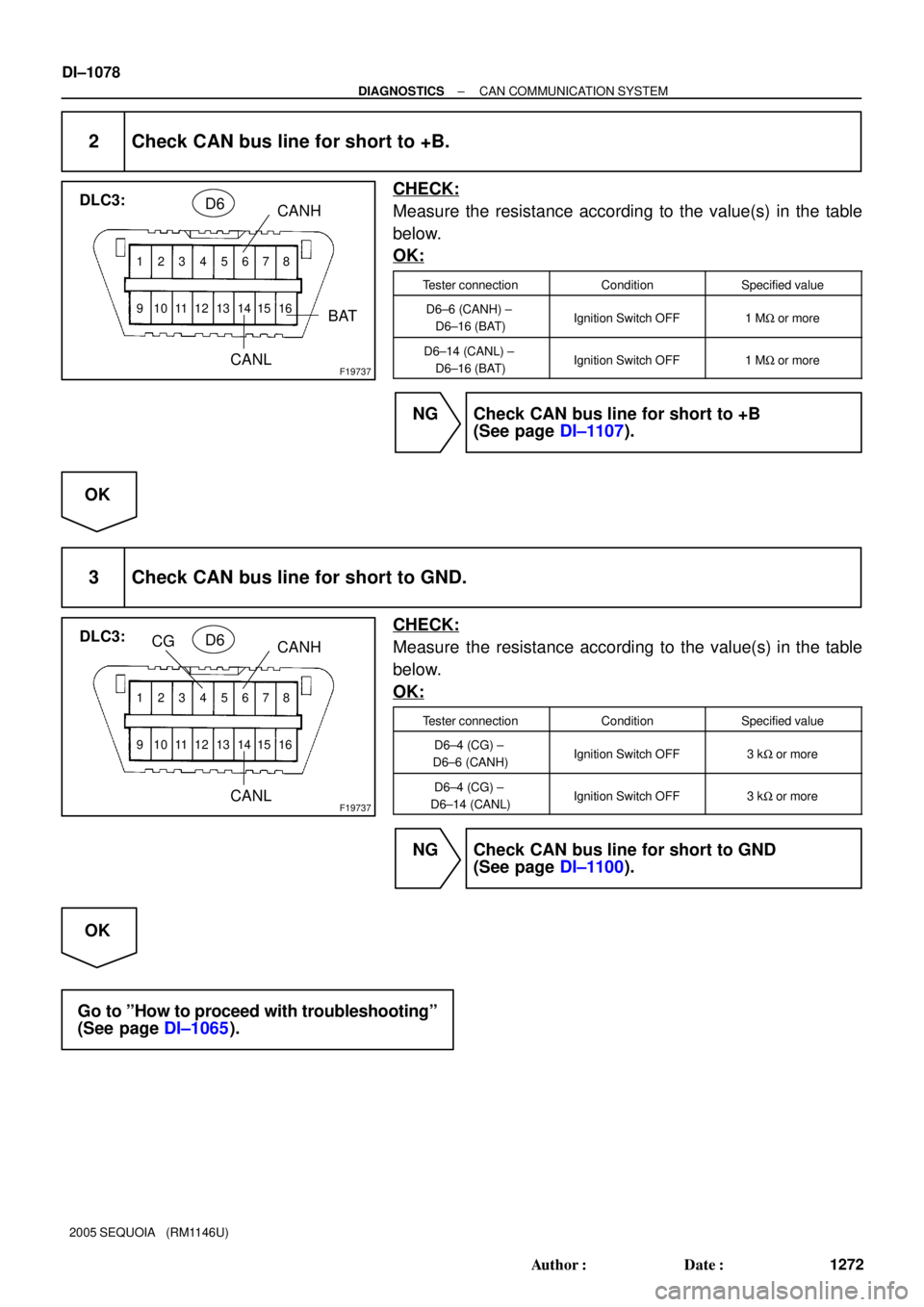
2 Check CAN bus line for short to +B.
CHECK:
Measure the resistance according to the value(s) in the table
below.
OK:
Tester connectionConditionSpecified value
D6±6 (CANH) ±
D6±16 (BAT)Ignition Switch OFF1 MW or more
D6±14 (CANL) ±
D6±16 (BAT)Ignition Switch OFF1 MW or more
NG Check CAN bus line for short to +B
(See page DI±1107).
OK
3 Check CAN bus line for short to GND.
CHECK:
Measure the resistance according to the value(s) in the table
below.
OK:
Tester connectionConditionSpecified value
D6±4 (CG) ±
D6±6 (CANH)Ignition Switch OFF3 kW or more
D6±4 (CG) ±
D6±14 (CANL)Ignition Switch OFF3 kW or more
NG Check CAN bus line for short to GND
(See page DI±1100).
OK
Go to ºHow to proceed with troubleshootingº
(See page DI±1065).