Page 1706 of 4323

1698 Author�: Date�:
2005 SEQUOIA (RM1146U)
SYSTEM DESCRIPTION
The power seat control system (w/ memory) is eq")
DIDE0±01
DI±1504± DIAGNOSTICSPOWER SEAT CONTROL SYSTEM (w/ Driving Position
Memory)
1698 Author�: Date�:
2005 SEQUOIA (RM1146U)
SYSTEM DESCRIPTION
The power seat control system (w/ memory) is equipped with the following functions:
�Manual operation of the driver side seat.
�Individual seat positions for two different drivers can be stored for the slide±reclining front±verti-
cal 8±way lifter.
�Similarly, power mirror positions for two different drivers can be stored. These are stored/restored
with the seat positions.
�The above operations are performed using serial communication.
�As a safety precaution, the system disallows seat position restoration unless the ignition switch
is ON, and the park/neutral position switch is in the P (park) position.
�Manual adjustment of the slide reclining lumbar can be performed even when the ECU is not
functional.
When the power seat control switch is operated, a command signal is sent to the position control ECU. The
position control ECU then activates the appropriate seat motor as needed. This memory system does not
use a seat position sensor. The seat position is detected by counting pulses that are output when the motor
turns. If there is no pulse output from the motor, the motor will stop operating. The ECU is designed so that
a malfunction of the seat memory system will not interfere with manual seat control. The seat memory switch
also sends signals to the position control ECU to memorize a given seat position. The seat memory switch
is later used to send signals to the position control ECU to return to one of the memorized positions.
Page 1707 of 4323
DIDE1±01
± DIAGNOSTICSPOWER SEAT CONTROL SYSTEM (w/ Driving Position
Memory)DI±1505
1699 Author�: Date�:
2005 SEQUOIA (RM1146U)
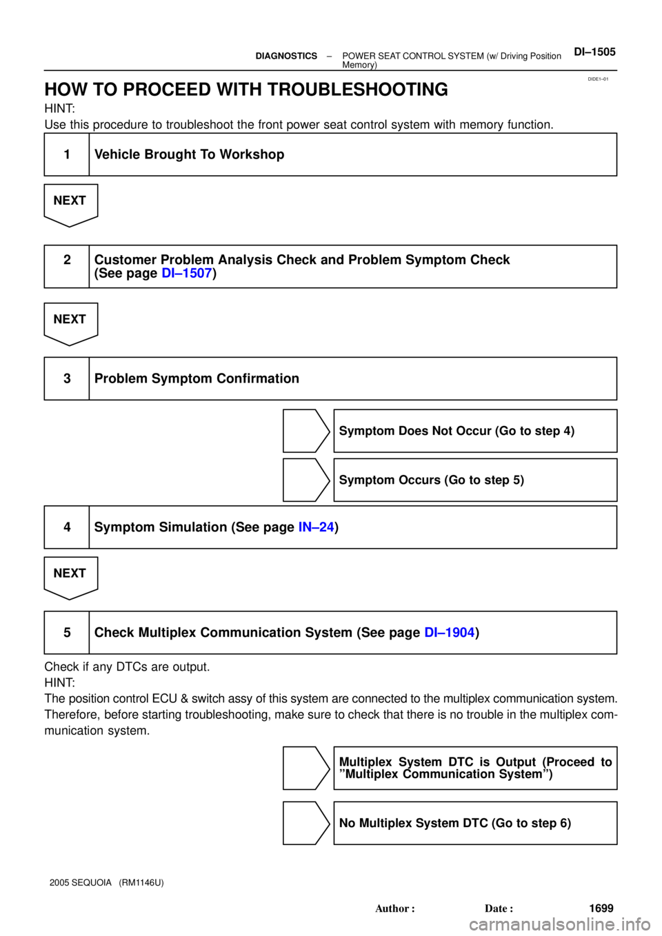
HOW TO PROCEED WITH TROUBLESHOOTING
HINT:
Use this procedure to troubleshoot the front power seat control system with memory function.
1 Vehicle Brought To Workshop
NEXT
2 Customer Problem Analysis Check and Problem Symptom Check
(See page DI±1507)
NEXT
3 Problem Symptom Confirmation
Symptom Does Not Occur (Go to step 4)
Symptom Occurs (Go to step 5)
4 Symptom Simulation (See page IN±24)
NEXT
5 Check Multiplex Communication System (See page DI±1904)
Check if any DTCs are output.
HINT:
The position control ECU & switch assy of this system are connected to the multiplex communication system.
Therefore, before starting troubleshooting, make sure to check that there is no trouble in the multiplex com-
munication system.
Multiplex System DTC is Output (Proceed to
ºMultiplex Communication Systemº)
No Multiplex System DTC (Go to step 6)
Page 1708 of 4323
DI±1506± DIAGNOSTICSPOWER SEAT CONTROL SYSTEM (w/ Driving Position
Memory)
1700 Author�: Date�:
2005 SEQUOIA (RM1146U)
6 Problem Symptoms Table (See page DI±1508)
NEXT
7 Identification of Problem
NEXT
8 Adjustment, Repair or Replace
NEXT
9 Confirmation Test
NEXT
End
Page 1709 of 4323
DIDE2±01
Inspector 's Name:
Customer 's Name
Date Vehicle
Brought InProduction Date VIN
Licence Plate No.
Odometer Reading/ /
/ /
Date Problem First Occurred
Frequency Problem Occurs/ /
ConstantIntermittent ( times a day)
km
miles
All functions do not operate.
Weather Conditions
When Problem
OccurredWeather
Outdoor
TemperatureOnly onceFine
Various/Others
CloudyRainySnowy
Hot
Cold ( �C ( �F))
WarmCool
Problem Symptoms
Sliding function does not operate.
Reclining function does not operate.
Front vertical function does not operate.
Lifter function does not operate.
Seat position memory function does not operate.
Others
POWER SEAT CONTROL SYSTEM Check Sheet
Lumbar support function does not operate.
± DIAGNOSTICSPOWER SEAT CONTROL SYSTEM (w/ Driving Position
Memory)DI±1507
1701 Author�: Date�:
2005 SEQUOIA (RM1146U)
CUSTOMER PROBLEM ANALYSIS CHECK
Page 1710 of 4323

1702 Author�: Date�:
2005 SEQUOIA (RM1146U)
PROBLEM SYMPTOMS TABLE
HINT:
�If the cause of the problem still ca")
DIDE4±01
DI±1508± DIAGNOSTICSPOWER SEAT CONTROL SYSTEM (w/ Driving Position
Memory)
1702 Author�: Date�:
2005 SEQUOIA (RM1146U)
PROBLEM SYMPTOMS TABLE
HINT:
�If the cause of the problem still cannot be determined after the corresponding inspection, proceed to
the next step shown in this table.
�The system uses multiplex communication. Check for DTCs for the multiplex communication system
before performing the following inspection.
SymptomSuspected AreaSee Page
Power seat does not operate (manual or memorized positions).1. Power source circuit
2. Position control ECU & switch assyDI±1514
BO±112
One function of power seat does not operate (manual or memo-
rized positions).1. Power seat motor circuit
2. Position control ECU & switch assyDI±1525
BO±112
One or all manual seat functions do not operate (memorized
positions OK).Position control ECU & switch assyBO±112
Memory function does not operate.
1. Power source circuit
2. Power seat memory switch circuit
3. Park/neutral position switch circuit
4. Door courtesy switch circuit
5. Position control ECU & switch assyDI±1514
DI±1518
DI±1528
DI±1533
BO±112
All memory functions do not operate or operate a little then stop
(manual functions OK).1. Power source circuit
2. Position control ECU & switch assyDI±1514
BO±112
One memory function does not operate or operates a little then
stops (manual functions OK).1. Power seat motor circuit
2. Position control ECU & switch assyDI±1525
BO±112
Lumbar support does not operate.Lumbar support control switch circuitDI±1521
The power seat control system does not control the storing and
restoring of the power mirror position.
1. Multiplex communication system
2. Driving position memory switch
3. Outer mirror assy
4. Position control ECU & switch assyDI±1904
BE±115
BE±115
BO±112
Page 1711 of 4323
DI±1509
1703 Author�: Date�:
2005 SEQUOIA (RM1146U)
TERMINALS OF ECU
1. CHECK POSITION CONTROL ECU & SWITC")
DIDE5±01
I27716
M7M6
± DIAGNOSTICSPOWER SEAT CONTROL SYSTEM (w/ Driving Position
Memory)DI±1509
1703 Author�: Date�:
2005 SEQUOIA (RM1146U)
TERMINALS OF ECU
1. CHECK POSITION CONTROL ECU & SWITCH ASSY
(a) Disconnect the M6 and M7 ECU & switch connectors.
(b) Check the voltage of each terminal of the wire harness side connectors.
Standard:
Symbols (Terminal No.)Wiring ColorTerminal DescriptionConditionSpecified Condition
GND (M7±1) ±
Body groundW±B ± Body groundGroundAlwaysBelow 1 V
+B (M7±5) ±
GND (M7±1)L±O ± W±BBatteryAlways10 to 14 V
SYSB (M6±8) ±
GND (M7±1)W±R ± W±BPower sourceAlways10 to 14 V
IG (M6±4) ± GND (M7±1)B±R ± W±BIgnition switchIgnition switch OFF " ONBelow 1 V " 10 to 14 V
MPX1 (M6±1) ±
GND (M7±1)W ± W±BCommunication signalAlways10 kW or higher
If the result is not as specified, there may be a malfunction on the wire harness side.
(c) Reconnect the M6 and M7 ECU & switch connectors.
(d) Check the voltage of each terminal of the connectors.
Standard:
Symbols (Terminal No.)Wiring ColorTerminal DescriptionConditionSpecified Condition
SLD+ (M7±2) ±
GND (M7±1)L ± W±BSliding motor signal
(Forward)Seat moving forward using
sliding switch " Others10 to 14 V " Below 1 V
SLD± (M7±3) ±
GND (M7±1)Y ± W±BSliding motor signal
(Rearward)Seat moving rearward us-
ing sliding switch " Others10 to 14 V " Below 1 V
FRV+ (M7±6) ±
GND (M7±1)G ± W±BFront vertical motor signal
(Upward)Seat cushion front portion
raising using front vertical
switch " Others
10 to 14 V " Below 1 V
FRV± (M7±4) ±
GND (M7±1)B ± W±BFront vertical motor signal
(Downward)Seat cushion front portion
lowering using front vertical
switch " Others
10 to 14 V " Below 1 V
LFT+ (M7±7) ±
GND (M7±1)W ± W±BLifter motor signal
(Upward)Seat raising using lifter
switch " Others10 to 14 V " Below 1 V
LFT± (M7±9) ±
GND (M7±1)V ± W±BLifter motor signal
(Downward)Seat lowering using lifter
switch " Others10 to 14 V " Below 1 V
Page 1712 of 4323
DI±1510± DIAGNOSTICSPOWER SEAT CONTROL SYSTEM (w/ Driving Position
Memory)
1704 Author�: Date�:
2005 SEQUOIA (RM1146U) RCL+ (M7±8) ±
GND (M7±1)
P ± W±BReclining motor signal
(Forward)Seat back moving forward
using reclining switch "
Others
10 to 14 V " Below 1 V
RCL± (M7±10) ±
GND (M7±1)BR ± W±BReclining motor signal
(Rearward)Seat back moving rear-
ward using reclining switch
" Others
10 to 14 V " Below 1 V
If the result is not as specified, the position control ECU & switch assy may be malfunctioning.
Page 1713 of 4323
DI±1511
1705 Author�: Date�:
2005 SEQUOIA (RM1146U)
DATA LIST / ACTIVE TEST
1. DATA LIST
HINT:
Using the DATA LIST dis")
DIDGG±01
± DIAGNOSTICSPOWER SEAT CONTROL SYSTEM (w/ Driving Position
Memory)DI±1511
1705 Author�: Date�:
2005 SEQUOIA (RM1146U)
DATA LIST / ACTIVE TEST
1. DATA LIST
HINT:
Using the DATA LIST displayed on the hand±held tester, you can read the value of the switch, sensor, etc.
without parts removal. Reading the DATA LIST as the first step of troubleshooting is one way to shorten the
labor time.
(a) Connect the hand±held tester to the DLC3.
(b) Turn the ignition switch ON.
(c) Read the DATA LIST according to the display on the tester.
D±SEAT:
ItemMeasurement Item/
Display (Range)Normal Condition
RECLIN SW REARReclining switch signal (Rearward)/
ON or OFFON: Reclining switch (Rearward) is ON
OFF: Reclining switch (Rearward) is OFF
RECLIN SW FRONTReclining switch signal (Forward)/
ON or OFFON: Reclining switch (Forward) is ON
OFF: Reclining switch (Forward) is OFF
F VTCL SW DOWNFront vertical switch signal (Downward)/
ON or OFFON: Front vertical switch (Downward) is ON
OFF: Front vertical switch (Downward) is OFF
F VTCL SW UPFront vertical switch signal (Upward)/
ON or OFFON: Front vertical switch (Upward) is ON
OFF: Front vertical switch (Upward) is OFF
LIFTER SW DOWNLifter switch signal (Downward)/
ON or OFFON: Lifter switch (Downward) is ON
OFF: Lifter switch (Downward) is OFF
LIFTER SW UPLifter switch signal (Upward)/
ON or OFFON: Lifter switch (Upward) is ON
OFF: Lifter switch (Upward) is OFF
SLIDE SW REARSliding switch signal (Rearward)/
ON or OFFON: Sliding switch (Rearward) is ON
OFF: Sliding switch (Rearward) is OFF
SLIDE SW FRONTSliding switch signal (Forward)/
ON or OFFON: Sliding switch (Forward) is ON
OFF: Sliding switch (Forward) is OFF
POWER VOLTAGEPower supply for position control ECU & switch/
MIN: 0 V, MAX: 19.89 VWithin range from 11 V to 14 V
IG SWIgnition switch status/
ON or OFFON Ignition switch is ON
OFF: Ignition switch is OFF
KEY UNLOCK SWKey unlock warning switch signal/
ON or OFFON: Key is in ignition key cylinder
OFF: Key is not in ignition key cylinder
D±DOOR WARN SWDoor courtesy switch signal/
ON or OFFON: Driver side door is open
OFF: Driver side door is closed
PNP SWPark/neutral position switch signal/
ON or OFFON: Shift lever in neutral position
OFF: Shift lever in any position except neutral
M2 SWSeat memory switch M2 signal/
ON or OFFON: Seat memory switch M2 is ON
OFF: Seat memory switch M2 is OFF
M1 SWSeat memory switch M1 signal/
ON or OFFON: Seat memory switch M1 is ON
OFF: Seat memory switch M1 is OFF
SET SWSeat memory set switch signal/
ON or OFFON: Memory set switch is ON
OFF: Memory set switch is OFF
SLIDE POSSeat sliding position/
MIN: ±4096, MAX: 4096Within range from ±4096 to 4096
RECLN POSSeatback position/
MIN: ±4096, MAX: 4096Within range from ±4096 to 4096
F VTCL POSSeat front vertical position/
MIN: ±4096 MAX: 4096Within range from ±4096 to 4096
LIFTER POSSeat lifter position/
MIN: ±4096 MAX: 4096Within range from ±4096 to 4096
MEM M1 SW
Driving position memorized with seat memory
switch M1/
MEM or NOT MEMMEM: Memorized
NOT MEM: Not memorized