Page 3098 of 4323
SA17R±04
F14272
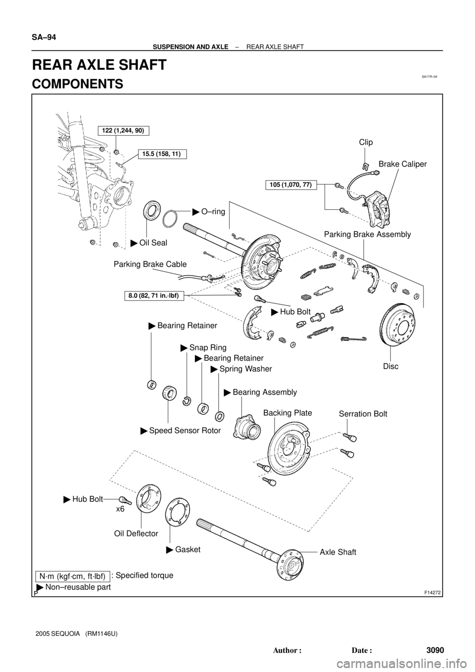
122 (1,244, 90)
� Oil Seal
� O±ring
Parking Brake Assembly
Disc Brake Caliper
� Bearing Retainer
� Speed Sensor Rotor
� Snap Ring
� Bearing Retainer
� Spring Washer
Backing PlateSerration Bolt
� Hub Bolt
Oil Deflector
� GasketAxle Shaft
N´m (kgf´cm, ft´lbf): Specified torque
� Non±reusable partx6
105 (1,070, 77)
15.5 (158, 11)
Clip
Parking Brake Cable
� Hub Bolt
8.0 (82, 71 in.´lbf)
� Bearing Assembly SA±94
± SUSPENSION AND AXLEREAR AXLE SHAFT
3090 Author�: Date�:
2005 SEQUOIA (RM1146U)
REAR AXLE SHAFT
COMPONENTS
Page 3099 of 4323

REMOVAL
1. REMOVE REAR WHEEL
Torque: 110 N´m (1,150 kgf´cm, 83 ft´lbf)")
SA17S±04
F14273
SST
F14274
F14275
± SUSPENSION AND AXLEREAR AXLE SHAFT
SA±95
3091 Author�: Date�:
2005 SEQUOIA (RM1146U)
REMOVAL
1. REMOVE REAR WHEEL
Torque: 110 N´m (1,150 kgf´cm, 83 ft´lbf)
2. DISCONNECT BRAKE LINE
Using SST, disconnect the brake line and remove the clip.
SST 09023±00101
Torque: 15.5 N´m (158 kgf´cm, 11 ft´lbf)
3. REMOVE BRAKE CALIPER AND DISC
Remove the 2 bolts, brake caliper and disc.
Torque: 105 N´m (1,070 kgf´cm, 77 ft´lbf)
4. CHECK BEARING BACKLASH AND AXLE SHAFT
DEVIATION
(a) Using a dial indicator, check the backlash in the bearing
shaft direction.
Maximum: 0.6 mm (0.024 in.)
If the backlash exceeds the maximum, replace the bearing.
(b) Using a dial indicator, check the deviation at the surface
of the axle shaft outside the hub bolt.
Maximum: 0.1 mm (0.0040 in.)
If the deviation exceeds the maximum, replace the axle shaft.
5. REMOVE PARKING BRAKE ASSEMBLY
(a) Remove the parking brake assembly (See page
BR±43).
(b) Remove the 2 bolts and pull out the parking brake cable
from the backing plate.
Torque: 8.0 N´m (82 kgf´cm, 71 in.´lbf)
(c) Use the same procedures described above to the other
side.
Page 3101 of 4323

DISASSEMBLY
1. REMOVE BEARING RETAINER (DIFFERENTIAL SIDE)")
SA24A±02
F14277
F14278
F14279
F05103
SST
F14280
± SUSPENSION AND AXLEREAR AXLE SHAFT
SA±97
3093 Author�: Date�:
2005 SEQUOIA (RM1146U)
DISASSEMBLY
1. REMOVE BEARING RETAINER (DIFFERENTIAL SIDE)
AND SPEED SENSOR ROTOR
(a) Attach the 4 nuts to the serration bolts and remove the
serration bolts from the backing plate using a hammer.
NOTICE:
Do not reuse the nuts previously removed from the vehicle.
(b) Grind the retainer and sensor rotor surfaces using a grind-
er, then pry them out with a chisel and hammer.
2. REMOVE SNAP RING FROM AXLE SHAFT
Using a snap ring expander, remove the snap ring.
3. REMOVE REAR AXLE SHAFT FROM BACKING
PLATE AND BEARING ASSEMBLY
(a) Attach the washers and nut to the serration bolts, then
torque the nuts to install the serration bolts to the backing
plate.
(b) Remove the 4 nuts from the serration bolts.
(c) Position SST on the backing plate with the 4 nuts.
SST 09521±25011, 09521±25021
(d) Using a press, remove the rear axle shaft, spring washer
and bearing retainer from the backing plate.
(e) Remove the SST.
SST 09521±25011, 09521±25021
4. REMOVE OIL DEFLECTOR AND GASKET
Using a brass bar and hammer, remove the 6 hub bolts, oil de-
flector and gasket.
Page 3102 of 4323
F14282
SA±98
± SUSPENSION AND AXLEREAR AXLE SHAFT
3094 Author�: Date�:
2005 SEQUOIA (RM1146U)
5. REMOVE BEARING ASSEMBLY
Attach the 4 nuts to the serration bolts and remove the serration
bolts from the backing plate using a hammer.
NOTICE:
Do not reuse the nuts previously removed from the vehicle.
Page 3105 of 4323

REASSEMBLY
1. INSTALL BEARING ASSEMBLY")
SA24B±02
F14284
Socket Wrench
F14286
F14287
SST
SST
F14288
SST
SST
± SUSPENSION AND AXLEREAR AXLE SHAFT
SA±101
3097 Author�: Date�:
2005 SEQUOIA (RM1146U)
REASSEMBLY
1. INSTALL BEARING ASSEMBLY
Position the backing plate on the bearing assembly and using
a press and 2 socket wrenches, install the serration bolts.
2. INSTALL OIL DEFLECTOR AND GASKET
Position a new gasket and oil deflector on the axle shaft and
install a washer and nut to a new hub bolt, as shown in the il-
lustration, and install the hub bolt by torquing the nut.
3. INSTALL REAR AXLE SHAFT TO BACKING PLATE
(a) Install the backing plate, spring washer and bearing re-
tainer on the rear axle shaft.
(b) Using SST and a press, install the rear axle shaft into the
backing plate.
SST 09631±12090, 09950±60020 (09951±01030)
4. INSTALL SNAP RING TO AXLE SHAFT
Using a snap ring expander, install a new snap ring.
5. INSTALL SPEED SENSOR ROTOR AND BEARING RE-
TAINER (DIFFERENTIAL SIDE)
Using SST and a press, install a new speed sensor rotor and
bearing retainer.
SST 09631±12090, 09950±60020 (09951±01030)
Standard length: 132.8 ± 1.0 mm (5.228 ± 0.039 in.)
Page 3108 of 4323
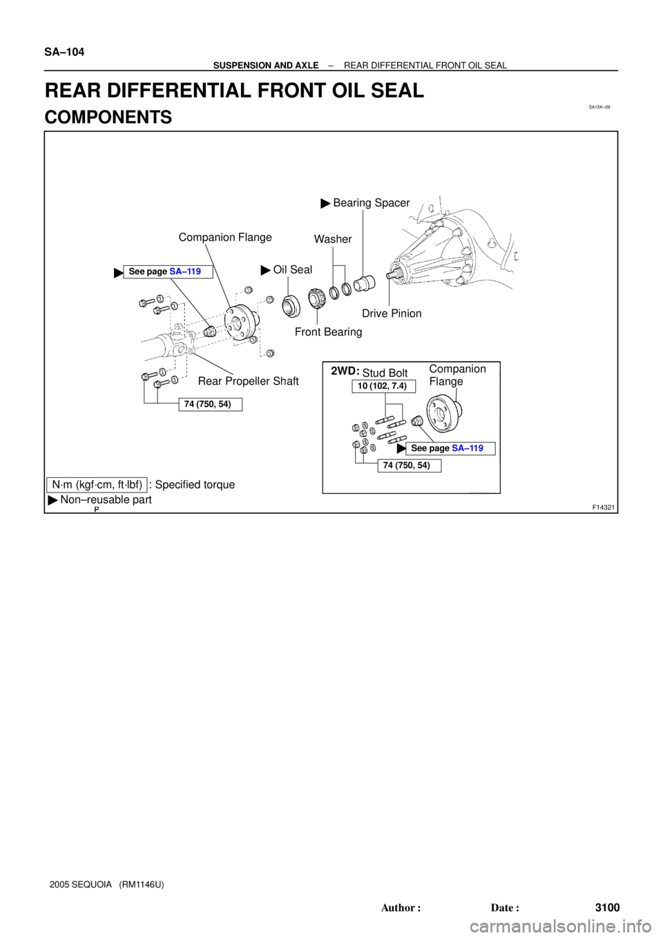
SA15K±09
F14321
� Oil Seal
Front Bearing
� Bearing Spacer
N´m (kgf´cm, ft´lbf) : Specified torque
� Non±reusable partCompanion Flange
Rear Propeller ShaftWasher
�
74 (750, 54)
Drive Pinion
2WD:
10 (102, 7.4)
74 (750, 54)
�See page SA±119
Stud BoltCompanion
Flange
See page SA±119
SA±104
± SUSPENSION AND AXLEREAR DIFFERENTIAL FRONT OIL SEAL
3100 Author�: Date�:
2005 SEQUOIA (RM1146U)
REAR DIFFERENTIAL FRONT OIL SEAL
COMPONENTS
Page 3110 of 4323
SA2349
SST
R13357
SST
R13358
SST SST
R13359
SST SA±106
± SUSPENSION AND AXLEREAR DIFFERENTIAL FRONT OIL SEAL
3102 Author�: Date�:
2005 SEQUOIA (RM1146U)
(b) 4WD:
(1) Using a chisel and hammer, loosen the staked part
of the nut.
(2) Using SST to hold the flange, remove the nut.
SST 09330±00021
(c) Using SST, remove the companion flange.
SST 09950±30012 (09951±03010, 09953±03010,
09954±03010, 09955±03030, 09956±03050)
4. REMOVE OIL SEAL
Using SST, remove the oil seal.
SST 09308±10010
5. REMOVE FRONT BEARING
Using SST, remove the front bearing from the drive pinion.
SST 09556±22010
6. REMOVE BEARING SPACER
(a) Remove the 2 washers.
(b) Remove the bearing spacer.
7. INSTALL NEW BEARING SPACER
(a) Install a new bearing spacer.
(b) Install the 2 washers.
8. INSTALL FRONT BEARING
(a) Place the front bearing.
Page 3111 of 4323

F14485
SST
F14522SST
± SUSPENSION AND AXLEREAR DIFFERENTIAL FRONT OIL SEAL
SA±107
3103 Author�: Date�:
2005 SEQUOIA (RM1146U)
(b) Using SST")
R13361
SST
R13360
SST
Vinyl Tape
F14486
40 mm
(1.57 in.)
F14485
SST
F14522SST
± SUSPENSION AND AXLEREAR DIFFERENTIAL FRONT OIL SEAL
SA±107
3103 Author�: Date�:
2005 SEQUOIA (RM1146U)
(b) Using SST and the companion flange, install the front
bearing then remove the companion flange.
SST 09950±30012 (09951±03010, 09953±03010,
09954±03010, 09955±03030, 09956±03050)
9. INSTALL NEW OIL SEAL
(a) Coat a new oil seal lip with MP grease.
(b) Using SST and a plastic hammer, install the oil seal until
its surface is flush with the differential carrier end.
SST 09316±12010, 09649±17010
HINT:
Connect 2 SST with vinyl tape.
10. INSTALL COMPANION FLANGE
(a) Place the companion flange on the drive pinion.
(b) Coat the threads of a new nut with hypoid gear oil.
(c) 2WD:
Install the companion flange nut.
(1) Install the 3 stud bolts so that the heads come out
40 mm (1.57 in.).
(2) Set the SST and install the 3 nuts to the companion
flange .
SST 09213±58013
(3) Install the other SST to the set SST to hold the com-
panion flange and torque the nut.
SST 09330±00021
Torque: 147 N´m (1,500 kgf´cm, 109 ft´lbf)
(4) Remove the 3 nuts, SST and stud bolts from the
companion flange.