Page 3508 of 4323
BE±96
± BODY ELECTRICALWIRELESS DOOR LOCK CONTROL SYSTEM
3500 Author�: Date�:
2005 SEQUOIA (RM1146U)
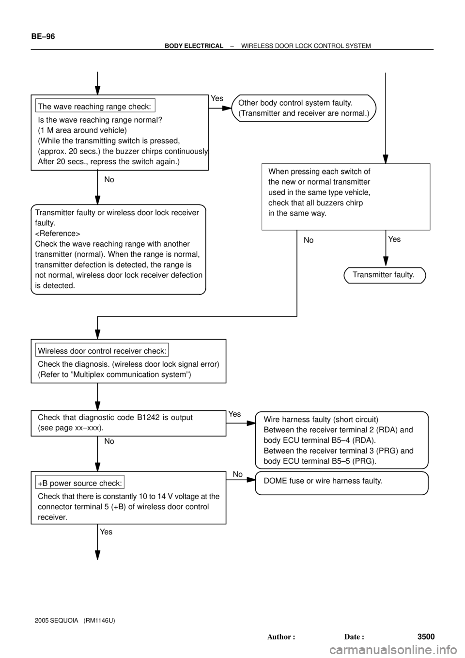
Transmitter faulty or wireless door lock receiver
faulty.
Check the wave reaching range with another
transmitter (normal). When the range is normal,
transmitter defection is detected, the range is
not normal, wireless door lock receiver defection
is detected.
The wave reaching range check:
Is the wave reaching range normal?
(1 M area around vehicle)
(While the transmitting switch is pressed,
(approx. 20 secs.) the buzzer chirps continuously.
After 20 secs., repress the switch again.)
NoOther body control system faulty.
(Transmitter and receiver are normal.)
Ye s
No
Wireless door control receiver check:
Check the diagnosis. (wireless door lock signal error)
(Refer to ºMultiplex communication systemº)
Check that diagnostic code B1242 is output
(see page xx±xxx).Wire harness faulty (short circuit)
Between the receiver terminal 2 (RDA) and
body ECU terminal B5±4 (RDA).
Between the receiver terminal 3 (PRG) and
body ECU terminal B5±5 (PRG).Ye s
No
When pressing each switch of
the new or normal transmitter
used in the same type vehicle,
check that all buzzers chirp
in the same way.
Transmitter faulty.
Ye s
DOME fuse or wire harness faulty.
Ye s
+B power source check:
Check that there is constantly 10 to 14 V voltage at the
connector terminal 5 (+B) of wireless door control
receiver.
No
Page 3513 of 4323
I18620
1
2
I12038
Wire Harness Side:
± BODY ELECTRICALWIRELESS DOOR LOCK CONTROL SYSTEM
BE±101
3505 Author�: Date�:
2005 SEQUOIA (RM1146U)
HINT:
�When the temperature of the battery is low, the judge can
not be made correctly.
When the outcome of the test is less than 2.1 V, conduct
the test again after leaving the battery in the place at 18
°C for more than 30 minutes.
�By auto power off function, the voltage becomes no load
voltage (more than 2.5 V) condition after 20 seconds from
the switch was pressed.
Make sure to read the voltage before of it.
�High voltage might be shown once or twice after leaving
the battery, judge should be made with the voltage shown
at the 3rd time or later.
(g) Disconnect the lead.
(h) Set the battery (lithium battery) in the transmitter.
(i) Install the cover, so that the rubber cover is not distorted
or slipped off.
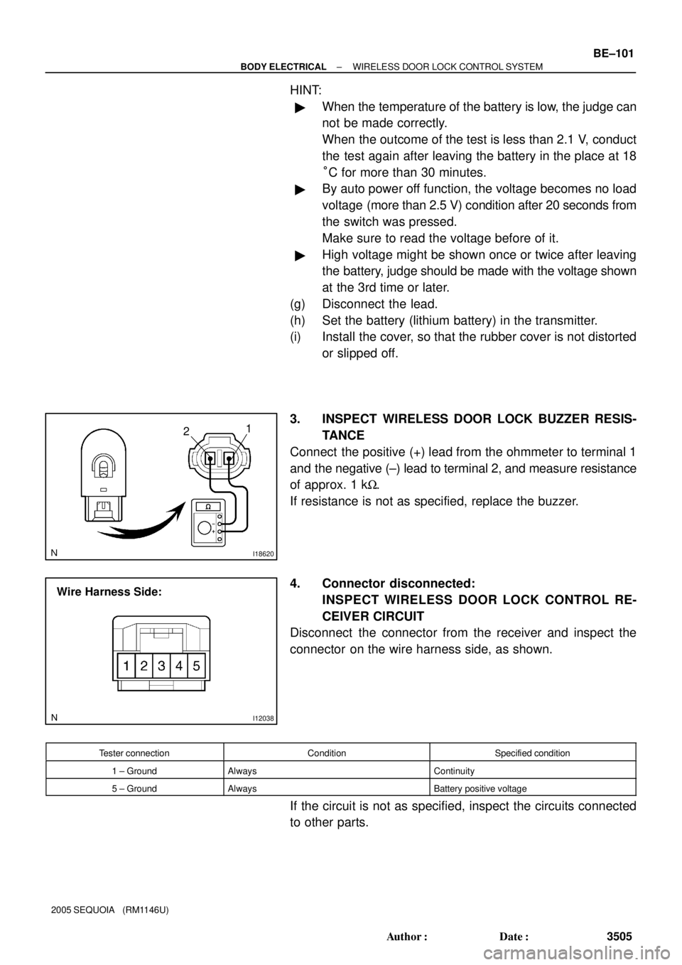
3. INSPECT WIRELESS DOOR LOCK BUZZER RESIS-
TANCE
Connect the positive (+) lead from the ohmmeter to terminal 1
and the negative (±) lead to terminal 2, and measure resistance
of approx. 1 kW.
If resistance is not as specified, replace the buzzer.
4. Connector disconnected:
INSPECT WIRELESS DOOR LOCK CONTROL RE-
CEIVER CIRCUIT
Disconnect the connector from the receiver and inspect the
connector on the wire harness side, as shown.
Tester connectionConditionSpecified condition
1 ± GroundAlwaysContinuity
5 ± GroundAlwaysBattery positive voltage
If the circuit is not as specified, inspect the circuits connected
to other parts.
Page 3520 of 4323
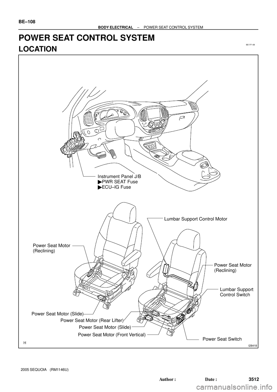
BE17F±08
I28418
Instrument Panel J/B
� PWR SEAT Fuse
� ECU±IG Fuse
Power Seat Motor
(Reclining)Lumbar Support Control Motor
Power Seat Motor (Slide)
Power Seat Motor (Slide)
Power Seat Motor (Front Vertical) Power Seat Motor (Rear Lifter)
Power Seat SwitchPower Seat Motor
(Reclining)
Lumbar Support
Control Switch
BE±108
± BODY ELECTRICALPOWER SEAT CONTROL SYSTEM
3512 Author�: Date�:
2005 SEQUOIA (RM1146U)
POWER SEAT CONTROL SYSTEM
LOCATION
Page 3521 of 4323
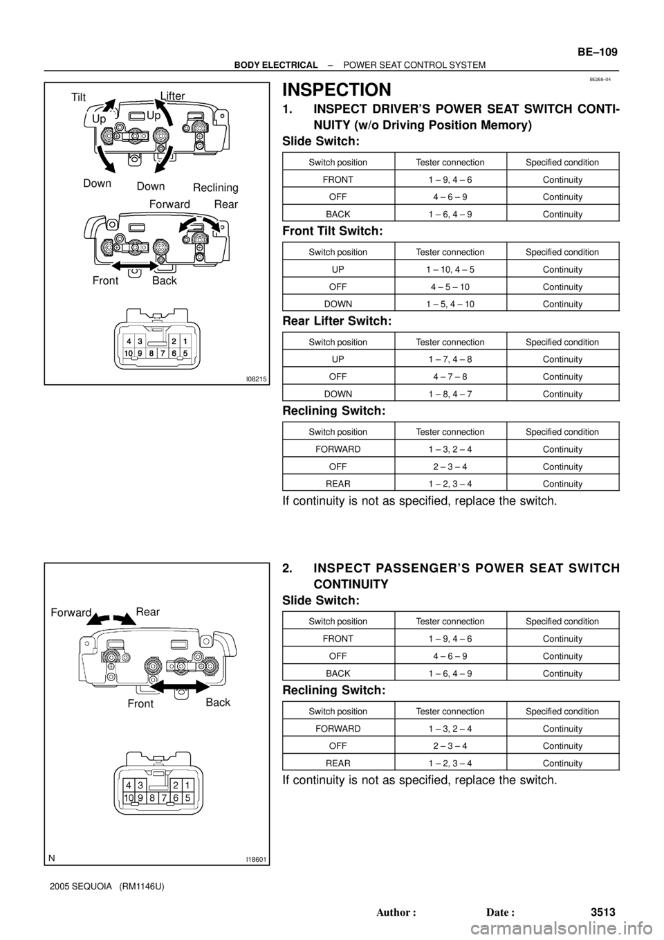
BE268±04
I08215
Lifter
Up
Down
Reclining Tilt
Up
Down
Front BackForward
Rear
I18601
Forward
FrontRear
Back
± BODY ELECTRICALPOWER SEAT CONTROL SYSTEM
BE±109
3513 Author�: Date�:
2005 SEQUOIA (RM1146U)
INSPECTION
1. INSPECT DRIVER'S POWER SEAT SWITCH CONTI-
NUITY (w/o Driving Position Memory)
Slide Switch:
Switch positionTester connectionSpecified condition
FRONT1 ± 9, 4 ± 6Continuity
OFF4 ± 6 ± 9Continuity
BACK1 ± 6, 4 ± 9Continuity
Front Tilt Switch:
Switch positionTester connectionSpecified condition
UP1 ± 10, 4 ± 5Continuity
OFF4 ± 5 ± 10Continuity
DOWN1 ± 5, 4 ± 10Continuity
Rear Lifter Switch:
Switch positionTester connectionSpecified condition
UP1 ± 7, 4 ± 8Continuity
OFF4 ± 7 ± 8Continuity
DOWN1 ± 8, 4 ± 7Continuity
Reclining Switch:
Switch positionTester connectionSpecified condition
FORWARD1 ± 3, 2 ± 4Continuity
OFF2 ± 3 ± 4Continuity
REAR1 ± 2, 3 ± 4Continuity
If continuity is not as specified, replace the switch.
2. INSPECT PASSENGER'S POWER SEAT SWITCH
CONTINUITY
Slide Switch:
Switch positionTester connectionSpecified condition
FRONT1 ± 9, 4 ± 6Continuity
OFF4 ± 6 ± 9Continuity
BACK1 ± 6, 4 ± 9Continuity
Reclining Switch:
Switch positionTester connectionSpecified condition
FORWARD1 ± 3, 2 ± 4Continuity
OFF2 ± 3 ± 4Continuity
REAR1 ± 2, 3 ± 4Continuity
If continuity is not as specified, replace the switch.
Page 3522 of 4323
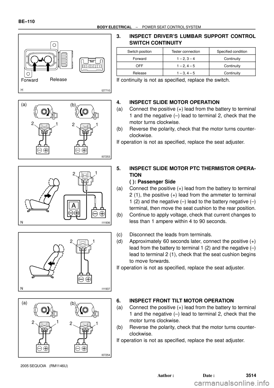
I27710
ForwardRelease
I07253
(a)
(b)
2
1
1 2
I11936
21
I11937
21
I07254
(a)
(b)
21
1 2
BE±110
± BODY ELECTRICALPOWER SEAT CONTROL SYSTEM
3514 Author�: Date�:
2005 SEQUOIA (RM1146U)
3. INSPECT DRIVER'S LUMBAR SUPPORT CONTROL
SWITCH CONTINUITY
Switch positionTester connectionSpecified condition
Forward1 ± 2, 3 ± 4Continuity
OFF1 ± 2, 4 ± 5Continuity
Release1 ± 3, 4 ± 5Continuity
If continuity is not as specified, replace the switch.
4. INSPECT SLIDE MOTOR OPERATION
(a) Connect the positive (+) lead from the battery to terminal
1 and the negative (±) lead to terminal 2, check that the
motor turns clockwise.
(b) Reverse the polarity, check that the motor turns counter-
clockwise.
If operation is not as specified, replace the seat adjuster.
5. INSPECT SLIDE MOTOR PTC THERMISTOR OPERA-
TION
( ): Passenger Side
(a) Connect the positive (+) lead from the battery to terminal
2 (1), the positive (+) lead from the ammeter to terminal
1 (2) and the negative (±) lead to the battery negative (±)
terminal, then move the seat cushion to the rear position.
(b) Continue to apply voltage, check that current changes to
less than 1 ampere within 4 to 90 seconds.
(c) Disconnect the leads from terminals.
(d) Approximately 60 seconds later, connect the positive (+)
lead from the battery to terminal 1 (2) and the negative (±)
lead to terminal 2 (1), check that the seat cushion begins
to move forwards.
If operation is not as specified, replace the seat adjuster.
6. INSPECT FRONT TILT MOTOR OPERATION
(a) Connect the positive (+) lead from the battery to terminal
1 and the negative (±) lead to terminal 2, check that the
motor turns clockwise.
(b) Reverse the polarity, check that the motor turns counter-
clockwise.
If operation is not as specified, replace the seat adjuster.
Page 3526 of 4323
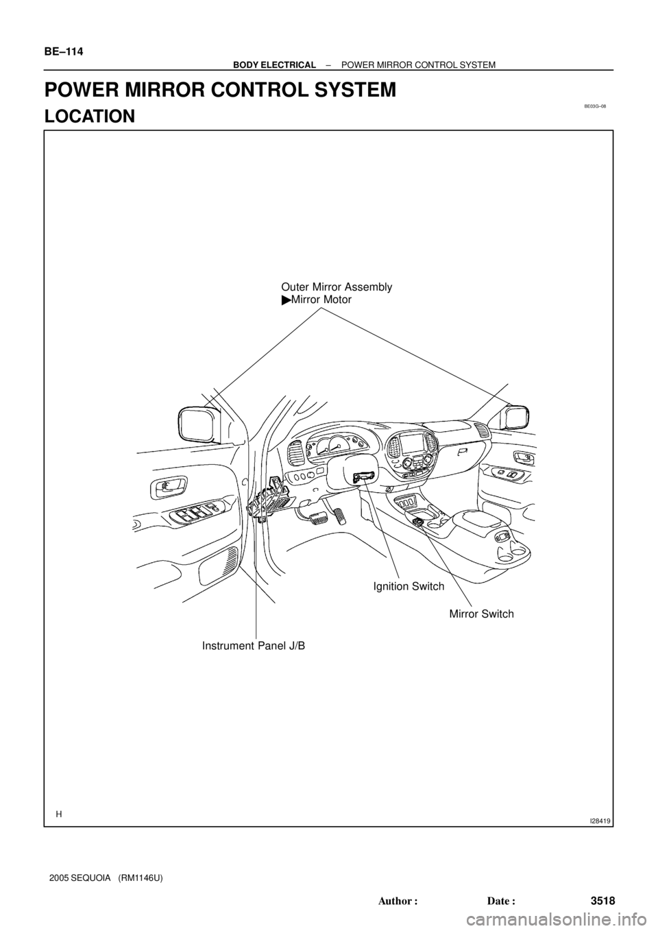
BE03G±08
I28419
Outer Mirror Assembly
� Mirror Motor
Instrument Panel J/BMirror Switch Ignition Switch
BE±114
± BODY ELECTRICALPOWER MIRROR CONTROL SYSTEM
3518 Author�: Date�:
2005 SEQUOIA (RM1146U)
POWER MIRROR CONTROL SYSTEM
LOCATION
Page 3527 of 4323
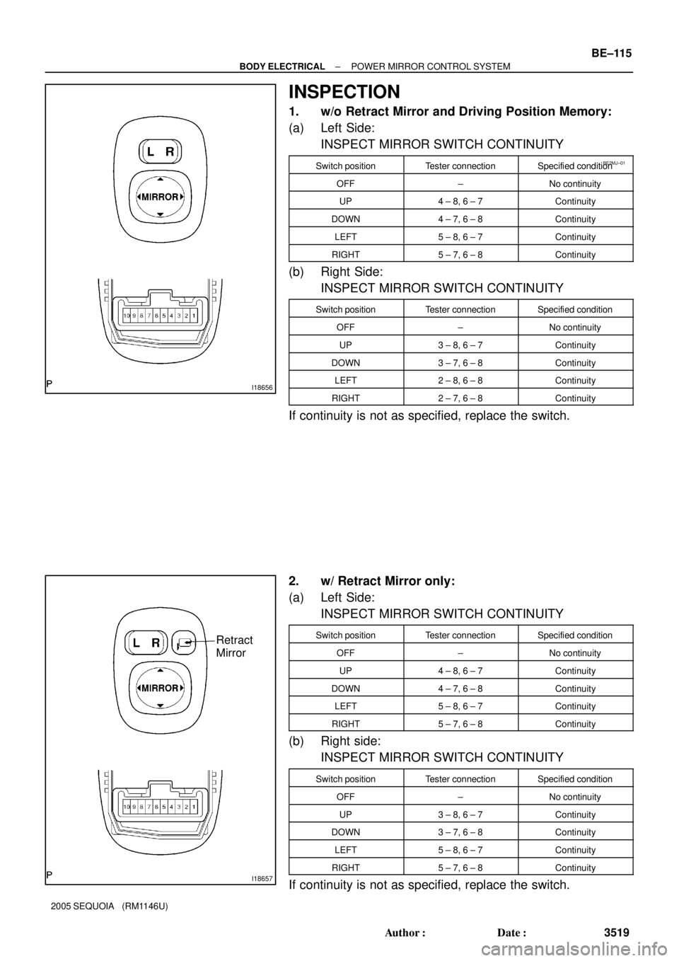
BE2MJ±01
I18656
I18657
Retract
Mirror
± BODY ELECTRICALPOWER MIRROR CONTROL SYSTEM
BE±115
3519 Author�: Date�:
2005 SEQUOIA (RM1146U)
INSPECTION
1. w/o Retract Mirror and Driving Position Memory:
(a) Left Side:
INSPECT MIRROR SWITCH CONTINUITY
Switch positionTester connectionSpecified condition
OFF±No continuity
UP4 ± 8, 6 ± 7Continuity
DOWN4 ± 7, 6 ± 8Continuity
LEFT5 ± 8, 6 ± 7Continuity
RIGHT5 ± 7, 6 ± 8Continuity
(b) Right Side:
INSPECT MIRROR SWITCH CONTINUITY
Switch positionTester connectionSpecified condition
OFF±No continuity
UP3 ± 8, 6 ± 7Continuity
DOWN3 ± 7, 6 ± 8Continuity
LEFT2 ± 8, 6 ± 8Continuity
RIGHT2 ± 7, 6 ± 8Continuity
If continuity is not as specified, replace the switch.
2. w/ Retract Mirror only:
(a) Left Side:
INSPECT MIRROR SWITCH CONTINUITY
Switch positionTester connectionSpecified condition
OFF±No continuity
UP4 ± 8, 6 ± 7Continuity
DOWN4 ± 7, 6 ± 8Continuity
LEFT5 ± 8, 6 ± 7Continuity
RIGHT5 ± 7, 6 ± 8Continuity
(b) Right side:
INSPECT MIRROR SWITCH CONTINUITY
Switch positionTester connectionSpecified condition
OFF±No continuity
UP3 ± 8, 6 ± 7Continuity
DOWN3 ± 7, 6 ± 8Continuity
LEFT5 ± 8, 6 ± 7Continuity
RIGHT5 ± 7, 6 ± 8Continuity
If continuity is not as specified, replace the switch.
Page 3528 of 4323
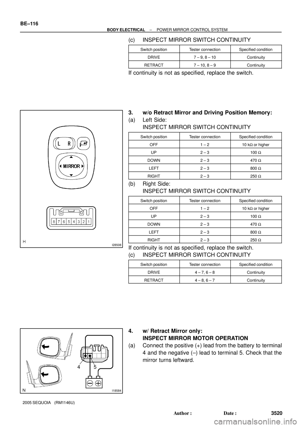
I28508
I18584
45
BE±116
± BODY ELECTRICALPOWER MIRROR CONTROL SYSTEM
3520 Author�: Date�:
2005 SEQUOIA (RM1146U)
(c) INSPECT MIRROR SWITCH CONTINUITY
Switch positionTester connectionSpecified condition
DRIVE7 ± 9, 8 ± 10Continuity
RETRACT7 ± 10, 8 ± 9Continuity
If continuity is not as specified, replace the switch.
3. w/o Retract Mirror and Driving Position Memory:
(a) Left Side:
INSPECT MIRROR SWITCH CONTINUITY
Switch positionTester connectionSpecified condition
OFF1 ± 210 kW or higher
UP2 ± 3100 W
DOWN2 ± 3470 W
LEFT2 ± 3800 W
RIGHT2 ± 3250 W
(b) Right Side:
INSPECT MIRROR SWITCH CONTINUITY
Switch positionTester connectionSpecified condition
OFF1 ± 210 kW or higher
UP2 ± 3100 W
DOWN2 ± 3470 W
LEFT2 ± 3800 W
RIGHT2 ± 3250 W
If continuity is not as specified, replace the switch.
(c) INSPECT MIRROR SWITCH CONTINUITY
Switch positionTester connectionSpecified condition
DRIVE4 ± 7, 6 ± 8Continuity
RETRACT4 ± 8, 6 ± 7Continuity
4. w/ Retract Mirror only:
INSPECT MIRROR MOTOR OPERATION
(a) Connect the positive (+) lead from the battery to terminal
4 and the negative (±) lead to terminal 5. Check that the
mirror turns leftward.