Page 2606 of 4323

A23310
String
A04339
A23311
Slightly Turn
A23312
SST
± ENGINE MECHANICALTIMING BELT
EM±19
2598 Author�: Date�:
2005 SEQUOIA (RM1146U)
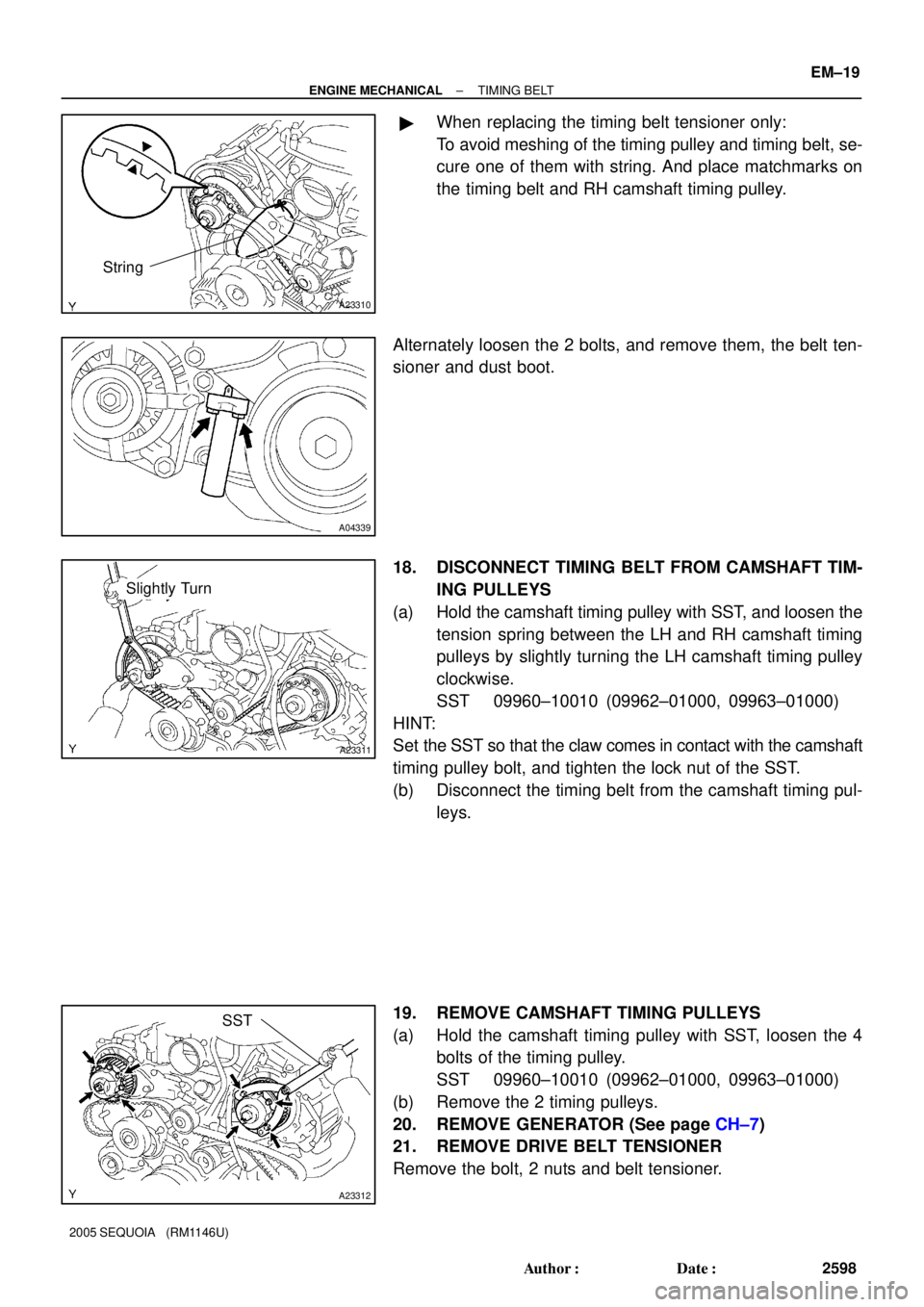
�When replacing the timing belt tensioner only:
To avoid meshing of the timing pulley and timing belt, se-
cure one of them with string. And place matchmarks on
the timing belt and RH camshaft timing pulley.
Alternately loosen the 2 bolts, and remove them, the belt ten-
sioner and dust boot.
18. DISCONNECT TIMING BELT FROM CAMSHAFT TIM-
ING PULLEYS
(a) Hold the camshaft timing pulley with SST, and loosen the
tension spring between the LH and RH camshaft timing
pulleys by slightly turning the LH camshaft timing pulley
clockwise.
SST 09960±10010 (09962±01000, 09963±01000)
HINT:
Set the SST so that the claw comes in contact with the camshaft
timing pulley bolt, and tighten the lock nut of the SST.
(b) Disconnect the timing belt from the camshaft timing pul-
leys.
19. REMOVE CAMSHAFT TIMING PULLEYS
(a) Hold the camshaft timing pulley with SST, loosen the 4
bolts of the timing pulley.
SST 09960±10010 (09962±01000, 09963±01000)
(b) Remove the 2 timing pulleys.
20. REMOVE GENERATOR (See page CH±7)
21. REMOVE DRIVE BELT TENSIONER
Remove the bolt, 2 nuts and belt tensioner.
Page 2608 of 4323

EM0KX±07
EM3336
NO !
P20079
P20633
± ENGINE MECHANICALTIMING BELT
EM±21
2600 Author�: Date�:
2005 SEQUOIA (RM1146U)
INSPECTION
1. INSPECT TIMING BELT
NOTICE:
�Do not bend, twist or turn the timing belt inside out.
�Do not allow the timing belt to come into contact with
oil, water or steam.
�Do not utilize timing belt tension when installing or re-
moving the mount bolt of the camshaft timing pulley.
If there is any defect, as shown in the illustration, check these
points:
(a) Premature parting
�Check for proper installation.
�Check the timing cover gasket for damage and
proper installation.
(b) If the belt teeth are cracked or damaged, check to see if
either camshaft is locked.
(c) If there is noticeable wear or cracks on the belt face,
check to see if there are nicks on the side of the idler
pulley lock and water pump.
(d) If there is wear or damage on even one side of the belt,
check the belt guide and the alignment of each pulley.
(e) If there is noticeable wear on the belt teeth, check timing
cover for damage and for foreign material on the pulley
teeth.
If necessary, replace the timing belt.
2. INSPECT IDLER PULLEYS
(a) Visually check the seal portion of the idler pulley for oil
leakage.
If leakage is found, replace the idler pulley.
(b) Check that the idler pulley turns smoothly.
If necessary, replace the idler pulley.
3. INSPECT TIMING BELT TENSIONER
(a) Visually check the seal portion of the tensioner for oil leak-
age.
HINT:
If there is only the faintest trace of oil on the seal on the push
rod side, the tensioner is all right.
If leakage is found, replace the tensioner.
Page 2609 of 4323
P20634
P20635
Protrusion EM±22
± ENGINE MECHANICALTIMING BELT
2601 Author�: Date�:
2005 SEQUOIA (RM1146U)
(b) Hold the tensioner with both hands and push the push rod
strongly as shown to check that it doesn't move.
If the push rod moves, replace the tensioner.
NOTICE:
Never hold the tensioner push rod facing downward.
(c) Measure the protrusion of the push rod from the housing
end.
Protrusion: 10.5 to 11.5 mm (0.413 to 0.453 in.)
If the protrusion is not as specified, replace the tensioner.
4. INSPECT WATER PUMP (See page CO±7)
Page 2611 of 4323

A04448
A23314
SST
A08660
A23315
SST
EM±24
± ENGINE MECHANICALTIMING BELT
2603 Author�: Date�:
2005 SEQUOIA (RM1146U)
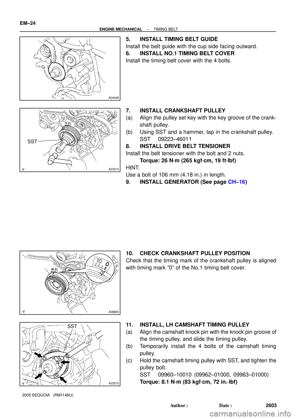
5. INSTALL TIMING BELT GUIDE
Install the belt guide with the cup side facing outward.
6. INSTALL NO.1 TIMING BELT COVER
Install the timing belt cover with the 4 bolts.
7. INSTALL CRANKSHAFT PULLEY
(a) Align the pulley set key with the key groove of the crank-
shaft pulley.
(b) Using SST and a hammer, tap in the crankshaft pulley.
SST 09223±46011
8. INSTALL DRIVE BELT TENSIONER
Install the belt tensioner with the bolt and 2 nuts.
Torque: 26 N´m (265 kgf´cm, 19 ft´lbf)
HINT:
Use a bolt of 106 mm (4.18 in.) in length.
9. INSTALL GENERATOR (See page CH±16)
10. CHECK CRANKSHAFT PULLEY POSITION
Check that the timing mark of the crankshaft pulley is aligned
with timing mark º0º of the No.1 timing belt cover.
11. INSTALL, LH CAMSHAFT TIMING PULLEY
(a) Align the camshaft knock pin with the knock pin groove of
the timing pulley, and slide the timing pulley.
(b) Temporarily install the 4 bolts of the camshaft timing
pulley.
(c) Hold the camshaft timing pulley with SST, and tighten the
pulley bolt.
SST 09960±10010 (09962±01000, 09963±01000)
Torque: 8.1 N´m (83 kgf´cm, 72 in.´lbf)
Page 2613 of 4323

P20636
1.27 mm
Hexagon Wrench
A04454
1.27 mm
Hexagon Wrench
A23307Turn
A23308
A23306
SST
EM±26
± ENGINE MECHANICALTIMING BELT
2605 Author�: Date�:
2005 SEQUOIA (RM1146U)
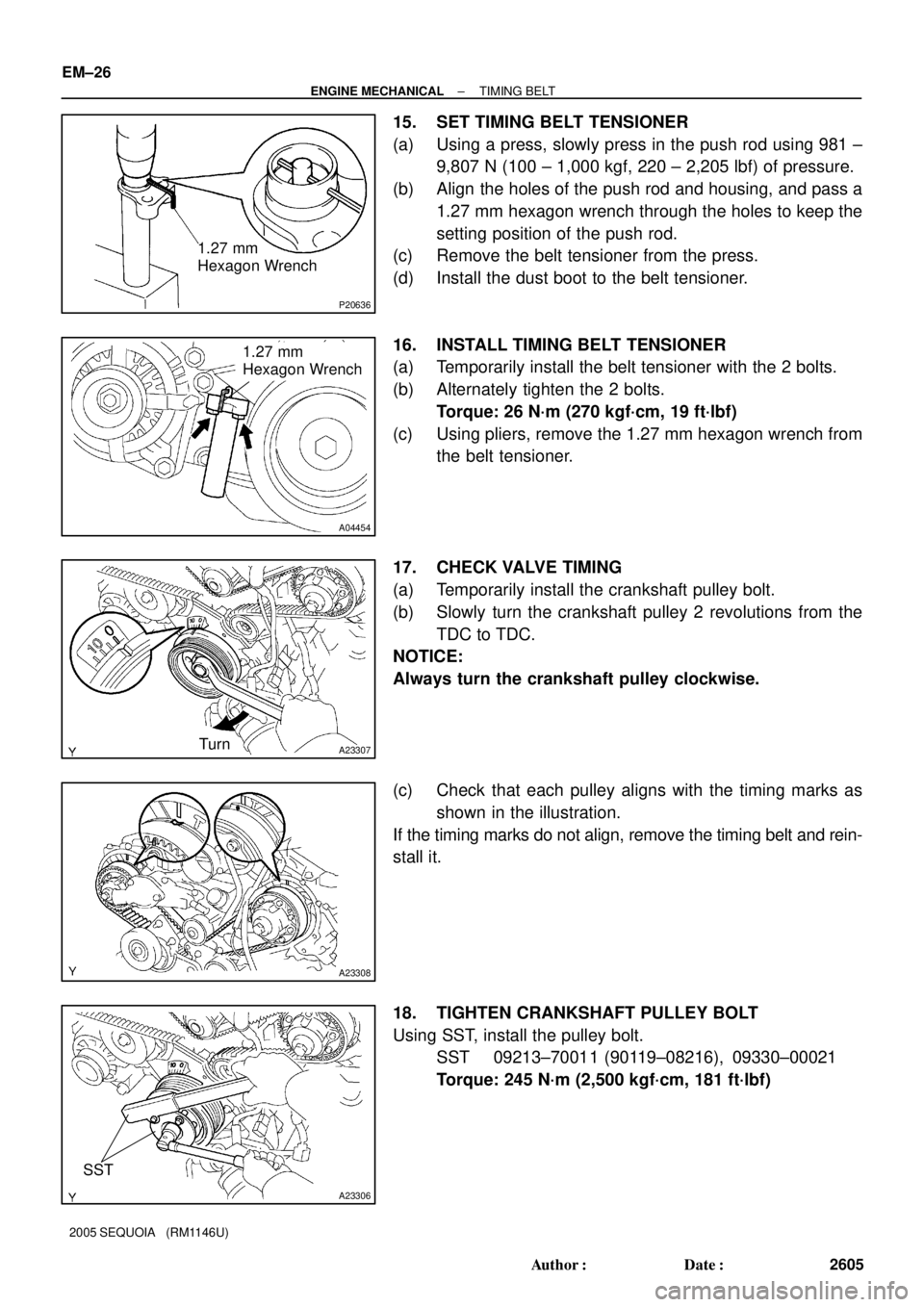
15. SET TIMING BELT TENSIONER
(a) Using a press, slowly press in the push rod using 981 ±
9,807 N (100 ± 1,000 kgf, 220 ± 2,205 lbf) of pressure.
(b) Align the holes of the push rod and housing, and pass a
1.27 mm hexagon wrench through the holes to keep the
setting position of the push rod.
(c) Remove the belt tensioner from the press.
(d) Install the dust boot to the belt tensioner.
16. INSTALL TIMING BELT TENSIONER
(a) Temporarily install the belt tensioner with the 2 bolts.
(b) Alternately tighten the 2 bolts.
Torque: 26 N´m (270 kgf´cm, 19 ft´lbf)
(c) Using pliers, remove the 1.27 mm hexagon wrench from
the belt tensioner.
17. CHECK VALVE TIMING
(a) Temporarily install the crankshaft pulley bolt.
(b) Slowly turn the crankshaft pulley 2 revolutions from the
TDC to TDC.
NOTICE:
Always turn the crankshaft pulley clockwise.
(c) Check that each pulley aligns with the timing marks as
shown in the illustration.
If the timing marks do not align, remove the timing belt and rein-
stall it.
18. TIGHTEN CRANKSHAFT PULLEY BOLT
Using SST, install the pulley bolt.
SST 09213±70011 (90119±08216), 09330±00021
Torque: 245 N´m (2,500 kgf´cm, 181 ft´lbf)
Page 2618 of 4323
A23302
RH No.3 Timing Belt Cover
No.2 Timing
Belt Cover
LH No.3 Timing Belt Cover Drive Belt Idler Pulley
Camshaft Position
Sensor ConnectorCover Plate
Oil Cooler Pipe Engine Wire
7.5 (76, 66 in.´lbf)
16 (160, 12)
7.5 (76, 66 in.´lbf)
N´m (kgf´cm, ft´lbf) : Specified torque
Wire Grommet
39 (400, 29)
A23373
Timing BeltRH Camshaft Timing Pulley
LH Camshaft Timing Pulley
Timing Belt Tensioner
Fan BracketDust Boot
16 (160, 12)
32 (330, 24)
26 (270, 19)
N´m (kgf´cm, ft´lbf) : Specified torque
8.1 (83, 72 in.´lbf)
± ENGINE MECHANICALCYLINDER HEAD
EM±31
2610 Author�: Date�:
2005 SEQUOIA (RM1146U)
Page 2828 of 4323
B17476
RH No.3 Timing Belt Cover
LH No.3 Timing Belt CoverNo.2 Timing Belt Cover
Camshaft Position
Sensor Connector
Engine Wire
Oil Cooler Pipe
Timing Belt
Fan Bracket Drive Belt Timing Pulley
Timing Belt Tensioner Dust Boot
N´m (kgf´cm, ft´lbf) : Specified torque Cover Plate
39 (400,29)
32 (330, 24)
16 (160, 12)
Water Bypass
Hose
Grommet
16 (160, 12)
245 (2,500, 181)
CO±4
± COOLINGWATER PUMP
2820 Author�: Date�:
2005 SEQUOIA (RM1146U)
Page 2829 of 4323
B17477
Generator Wire
Generator Connector
Generator
Crankshaft PulleyDrive Belt Tensioner
No.1 Timing Belt Cover
Timing Belt
Timing Belt Guide
(Crankshaft Angle Sensor Plate)No.2 Idler Pulley
Timing Belt Cover SpacerGasket
N´m (kgf´cm, ft´lbf) : Specified torque
� Non±reusable partWater Inlet Housing
Assembly
Water Pump � O±Ring
� Gasket � O±Ring
39 (400, 29)
18 (185, 13)
21 (215, 15)
Wire
Clamp
PS Vane Pump
(100 A Type Generator)
15.5 (158, 11)
39 (400, 29)
34.5 (350, 25)
± COOLINGWATER PUMP
CO±5
2821 Author�: Date�:
2005 SEQUOIA (RM1146U)