Page 2938 of 4323

D02002
AT±22
± AUTOMATIC TRANSMISSION (A750E, A750F)COLUMN SHIFT ASSEMBLY
2930 Author�: Date�:
2005 SEQUOIA (RM1146U)
(g) Install the parking lock cable No. 2 to column upper brack-
et with the clip.
(h) Install the cable end to the sliding block of the column up-
per bracket with the screw.
Torque: 2.2 N´m (23 kgf´cm, 19 in.´lbf)
(i) After installation, check the following items.
(1) When the pedal button is pushed, shift lever should
be locked.
(2) When the pedal button is released, shift lever
should be unlocked.
4. INSTALL STEERING COLUMN ASSEMBLY
(See page SR±23)
5. ADJUST CABLE HOUSING
(a) Shift the shift lever to the P position.
(b) Turn the ignition key to the LOCK position.
(c) Loosen the 2 bolts and adjust the cable housing.
HINT:
�Pedal button should touch the pedal plate cushion.
�Brake pedal should not be moved by the pedal button.
�Cable housing should not be toughed the brake pedal
and the brake pedal plate cushion.
(d) Torque the 2 bolts.
Torque: 10.5 N´m (110 kgf´cm, 8 ft´lbf)
6. CONFIRM SHIFT LOCK SYSTEM OPERATION
(a) Only when the brake pedal is engaged and the ignition
key is not in the LOCK position, the shift lever can be
shifted from the P position to other positions.
When the shift lever is in the P position and the brake ped-
al is released, the shift lever cannot be shifted from P posi-
tion to other positions.
(b) When the shift lever is not in the P position, the ignition
key cannot be turned to the LOCK position.
Only when the shift lever is in the P position, the ignition
key can be removed.
(c) Cable No. 1 and No. 2 should not be deformed by other
parts located around the steering column.
Page 3013 of 4323

SA3213
AB
Front
C D
R13228
R13229
FA0018
AB
FrontA
B
A: Inside
B: Outside
± SUSPENSION AND AXLEFRONT WHEEL ALIGNMENT
SA±9
3005 Author�: Date�:
2005 SEQUOIA (RM1146U)
5. INSPECT TOE±IN
Toe±in (total):
UCK35L±GKBSKA
Tire size: P245/70R16
Tire size: P265/70R16 and P265/65R17
Tire size: P265/65R17 (*1)
UCK35L±GKBLKA
UCK45L±GKBSKA
Tire size: P265/70R16 (*1)
UCK45L±GKBLKA
A + B: 0°05' ± 0°09' (0.09° ± 0.15°)
C ± D: 1.19 ± 2 mm (0.05 ± 0.08 in.)
A + B: 0°05' ± 0°09' (0.09° ± 0.15°)
C ± D: 1.29 ± 2 mm (0.05 ± 0.08 in.)
A + B: 0°05' ± 0°09' (0.09° ± 0.15°)
C ± D: 1.28 ± 2 mm (0.05 ± 0.08 in.)
A + B: 0°05' ± 0°09' (0.08° ± 0.15°)
C ± D: 1.15 ± 2 mm (0.05 ± 0.08 in.)
A + B: 0°05' ± 0°09' (0.08° ± 0.15°)
C ± D: 1.08 ± 2 mm (0.04 ± 0.08 in.)
A + B: 0°05' ± 0°09' (0.08° ± 0.15°)
C ± D: 1.07 ± 2 mm (0.04 ± 0.08 in.)
A + B: 0°04' ± 0°09' (0.07° ± 0.15°)
C ± D: 0.99 ± 2 mm (0.04 ± 0.08 in.)
(*1): Air suspension models only
If the toe±in is not within the specified values, adjust the rack
ends.
6. ADJUST TOE±IN AND WHEEL ANGLE
(a) Remove the 2 clips.
(b) Loosen the tie rod end lock nuts.
(c) Turn the right and left rack ends by an equal amount to
adjust the toe±in.
HINT:
Try to adjust the toe±in to the center of the specified values.
(d) Make sure that the lengths of the right and left rack ends
are the same.
Rack end length difference: 1.5 mm (0.059 in.) or less
(e) Tighten the tie rod end lock nuts.
Torque: 55 N´m (560 kgf´cm, 41 ft´lbf)
(f) Place the boots on the seats and install the clips.
HINT:
Make sure that the boots are not twisted.
(g) Inspect the wheel angle.
Turn the steering wheel fully and measure the turning
angle.
Page 3025 of 4323
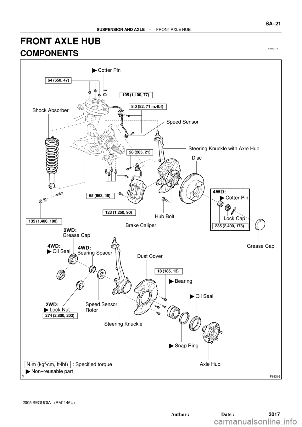
SA143±10
F14316
N´m (kgf´cm, ft´lbf) : Specified torque
� Non±reusable part
64 (650, 47)
Brake CaliperHub Bolt � Cotter Pin
105 (1,100, 77)
8.0 (82, 71 in.´lbf)
Speed Sensor
Shock Absorber
135 (1,400, 100)
65 (663, 48)
123 (1,250, 90)
28 (285, 21)Steering Knuckle with Axle Hub
Disc
4WD:
� Cotter Pin
235 (2,400, 173)
Lock Cap
Grease Cap
Grease Cap2WD:
4WD:
� Oil Seal
Speed Sensor
Rotor
Dust Cover
Steering Knuckle
18 (185, 13)
� Oil Seal � Bearing
� Snap Ring
Axle Hub
Bearing Spacer4WD:
274 (2,800, 203)
� Lock Nut 2WD:
± SUSPENSION AND AXLEFRONT AXLE HUB
SA±21
3017 Author�: Date�:
2005 SEQUOIA (RM1146U)
FRONT AXLE HUB
COMPONENTS
Page 3030 of 4323

SA146±08
R13277
SST
SST
R13278
SST
SST
R13279
SST
R13215
SST
R13418
SST SA±26
± SUSPENSION AND AXLEFRONT AXLE HUB
3022 Author�: Date�:
2005 SEQUOIA (RM1146U)
REASSEMBLY
1. INSTALL NEW BEARING
(a) Using SST and a press, install a new bearing to the steer-
ing knuckle.
SST 09527±17011, 09950±60020 (09951±00910)
(b) Using snap ring pliers, install a new snap ring.
2. INSTALL NEW OIL SEAL (OUTSIDE)
(a) Using SST and a plastic hammer, install a new oil seal
(outside).
SST 09223±15030, 09527±17011
(b) Coat MP grease to the oil seal lip.
3. INSTALL AXLE HUB TO STEERING KNUCKLE
(a) Install the dust cover to the steering knuckle with the 4
bolts.
Torque: 18 N´m (185 kgf´cm, 13 ft´lbf)
(b) Using SST and a press, install the axle hub to the steering
knuckle.
SST 09649±17010
4. INSTALL SPEED SENSOR ROTOR
NOTICE:
Do not scratch the serration of the speed sensor rotor.
5. 2WD:
INSTALL NEW LOCK NUT
(a) Using SST, install and torque a new lock nut to the axle
hub.
SST 09318±12010
Torque: 274 N´m (2,800 kgf´cm, 203 ft´lbf)
(b) Using a chisel and hammer, stake the lock nut.
6. 4WD:
INSTALL BEARING SPACER
Using SST and a press, install the bearing spacer.
SST 09950±60010 (09951±00650),
09950±70010 (09951±07150)
7. 2WD:
INSTALL GREASE CAP
Page 3032 of 4323
SA23J±05
SA±28
± SUSPENSION AND AXLEFRONT AXLE HUB
3024 Author�: Date�:
2005 SEQUOIA (RM1146U)
INSTALLATION
1. INSTALL STEERING KNUCKLE
(a) 4WD:
Insert the drive shaft into the axle hub and temporarily tighten the nut.
NOTICE:
Be careful not to damage the oil seal and drive shaft boot.
(b) Connect the steering knuckle to the upper suspension arm.
(c) Install the nut and a new cotter pin.
If the holes for the cotter pin are not aligned, tighten the nut further up to 60°.
Torque: 105 N´m (1,100 kgf´cm, 77 ft´lbf)
2. CONNECT LOWER BALL JOINT
Connect the lower ball joint to the steering knuckle with the 4 bolts.
Torque: 65 N´m (663 kgf´cm, 48 ft´lbf)
3. INSTALL SHOCK ABSORBER (See page SA±70)
4. INSTALL BRAKE CALIPER
(a) Install the disc, brake caliper and 2 bolts.
Torque: 123 N´m (1,250 kgf´cm, 90 ft´lbf)
(b) Install the brake line clamp to the steering knuckle with the bolt.
Torque: 28 N´m (285 kgf´cm, 21 ft´lbf)
5. CONNECT SPEED SENSOR AND WIRE HARNESS CLAMP
Connect the speed sensor and wire harness clamp to the steering knuckle with the 2 bolts.
Torque: 8.0 N´m (82 kgf´cm, 71 ft´lbf)
6. 4WD:
INSTALL DRIVE SHAFT LOCK NUT
(a) While applying the brakes, tighten the nut.
Torque: 235 N´m (2,400 kgf´cm, 173 ft´lbf)
(b) Install the lock cap and a new cotter pin.
If the holes for the cotter pin are not aligned, tighten the nut further up to 60°.
7. INSTALL GREASE CAP
8. INSTALL FRONT WHEEL
Torque: 110 N´m (1,150 kgf´cm, 83 ft´lbf)
9. DEPRESS BRAKE PEDAL SEVERAL TIMES
10. CHECK FRONT WHEEL ALIGNMENT (See page SA±4)
11. CHECK SPEED SENSOR SIGNAL (See page DI±899)
12. PERFORM ZERO POINT CALIBRATION OF STEERING ANGLE, MASTER CYLINDER PRES-
SURE, YAW RATE AND DECELERATION SENSORS (See page DI±897)
Page 3033 of 4323

SA24P±03
F07264
R13372
SST
R13373WasherNut
± SUSPENSION AND AXLEFRONT WHEEL HUB BOLT
SA±29
3025 Author�: Date�:
2005 SEQUOIA (RM1146U)
FRONT WHEEL HUB BOLT
REPLACEMENT
1. REMOVE FRONT WHEEL
2. REMOVE BRAKE CALIPER AND DISC
(a) Remove the bolt and brake line clamp from the steering
knuckle.
(b) Remove the 2 bolts, brake caliper and disc.
(c) Support the brake caliper securely.
3. REMOVE HUB BOLT
Using SST and a screwdriver or an equivalent, remove the hub
bolt.
SST 09650±17011
4. INSTALL HUB BOLT
(a) Install a washer and nut to a new hub bolt as shown in the
illustration.
(b) Using a screwdriver or an equivalent to hold, install the
hub bolt by torquing the nut.
(c) Remove the nut and washer.
5. INSTALL BRAKE DISC AND CALIPER
(a) Install the brake disc, caliper and 2 bolts.
Torque: 123 N´m (1,250 kgf´cm, 90 ft´lbf)
(b) Install the brake line clamp to the steering knuckle with the
bolt.
Torque: 28 N´m (285 kgf´cm, 21 ft´lbf)
6. INSTALL FRONT WHEEL
Torque: 110 N´m (1,150 kgf´cm, 83 ft´lbf)
7. DEPRESS BRAKE PEDAL SEVERAL TIMES
Page 3040 of 4323
SA14I±10
SA±36
± SUSPENSION AND AXLEFRONT DRIVE SHAFT
3032 Author�: Date�:
2005 SEQUOIA (RM1146U)
INSTALLATION
1. INSTALL DRIVE SHAFT TO DIFFERENTIAL
(a) Install a new snap ring to the inboard joint shaft.
(b) Apply gear oil to the inboard joint shaft and differential case sliding surface.
(c) Set the snap ring with opening side facing downward.
(d) Using a brass bar and hammer, install the drive shaft.
NOTICE:
Be careful not to damage the dust cover and oil seal.
HINT:
Whether the inboard joint shaft is in contact with the pinion shaft or not can be known from the sound or feel-
ing when driving.
(e) Check that there is 2 ± 3 mm (0.08 ± 0.12 in.) of play in the axial direction.
(f) Check that the drive shaft cannot be removed by hand.
2. LH drive shaft:
INSTALL LH SHOCK ABSORBER (See page SA±70)
3. CONNECT DRIVE SHAFT TO STEERING KNUCKLE
NOTICE:
Be careful not to damage the oil seal, boots and dust seal.
4. CONNECT LOWER SUSPENSION ARM TO LOWER BALL JOINT
(a) Connect the lower suspension arm to the lower ball joint.
(b) Install the nut and a new cotter pin.
If the holes for the cotter pin are not aligned, tighten the nut further up to 60°.
HINT:
Face the hole for the cotter pin forward.
Torque: 140 N´m (1,450 kgf´cm, 103 ft´lbf)
5. INSTALL DRIVE SHAFT LOCK NUT
(a) While applying brakes, install the nut.
Torque: 235 N´m (2,400 kgf´cm, 173 ft´lbf)
(b) Install the lock cap and a new cotter pin.
If the holes for the cotter pin are not aligned, tighten the nut further up to 60°.
6. FILL DIFFERENTIAL WITH HYPOID GEAR OIL (See page SA±38)
7. INSTALL ENGINE UNDER COVER
8. INSTALL FRONT WHEEL
Torque: 110 N´m (1,150 kgf´cm, 83 ft´lbf)
Page 3078 of 4323
SA187±06
SA±74
± SUSPENSION AND AXLEFRONT UPPER SUSPENSION ARM
3070 Author�: Date�:
2005 SEQUOIA (RM1146U)
INSTALLATION
1. INSTALL UPPER SUSPENSION ARM
Install the upper suspension arm with the 2 washers, bolt and nut.
Torque: 98 N´m (1,000 kgf´cm, 72 ft´lbf)
HINT:
After stabilizing the suspension, torque the nut.
2. INSTALL BRAKE AND FUEL LINE CLAMP
Torque: 5.5 N´m (56 kgf´cm, 49 in.´lbf)
3. INSTALL FENDER APRON SEAL REAR
4. CONNECT UPPER BALL JOINT
(a) Connect the upper ball joint to the upper suspension arm.
(b) Install the nut and a new cotter pin.
If the holes for the cotter pin are not aligned, tighten the nut further up to 60°.
Torque: 105 N´m (1,100 kgf´cm, 77 ft´lbf)
5. CONNECT SPEED SENSOR WIRE HARNESS CLAMPS
Torque: 8.0 N´m (82 kgf´cm, 71 in.´lbf)
6. INSTALL SHOCK ABSORBER WITH COIL SPRING (See page SA±70)
7. CHECK FRONT WHEEL ALIGNMENT (See page SA±4)
8. PERFORM ZERO POINT CALIBRATION OF STEERING ANGLE, MASTER CYLINDER PRES-
SURE, YAW RATE AND DECELERATION SENSORS (See page DI±897)