Page 3247 of 4323
SR1F3±03
F17895
Steering Wheel Pad
Steering
Wheel
Column Lower
CoverCombination
SwitchSteering Column Assembly
Transmission Control
Cable Assembly
Lower LH Finish PanelColumn Hole
Cover No. 2
No. 2 Universal
Joint Assembly
No. 2 Heater to Register Dust Torx® Screw
35 (360, 26)
35 (360, 26)
8.0 (82, 71 in.´lbf)
26 (260, 19)
26 (260, 19)
8.8 (90, 78 in.´lbf)
50 (510, 37)
8.8 (90, 78 in.´lbf)
Front Door Scuff PlateCowl Side Trim
Hood Lock
Release Lever
8.0 (82, 71 in.´lbf)
Side Panel
No. 2 Intermediate
Shaft AssemblyBrake Pedal
Return Spring
Column Upper Cover
N´m (kgf´cm, ft´lbf): Specified torque
Steering Wheel Lower
No. 3 Cover
Steering Wheel Lower
No. 2 Cover
35 (360, 26)
Sliding Yoke
Torx® Screw SR±12
± STEERINGTILT STEERING COLUMN
3239 Author�: Date�:
2005 SEQUOIA (RM1146U)
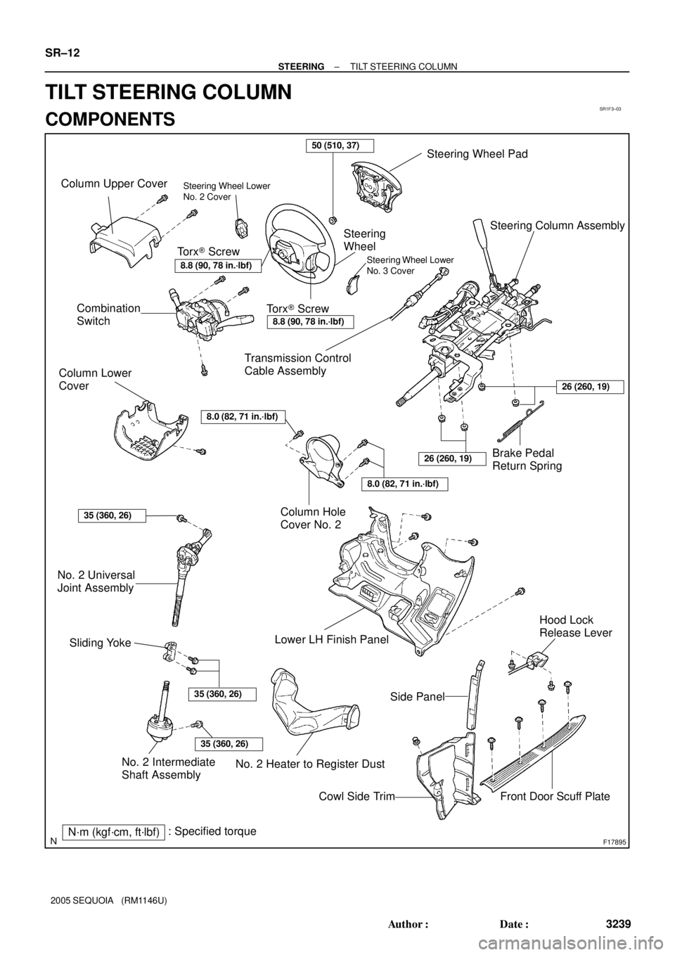
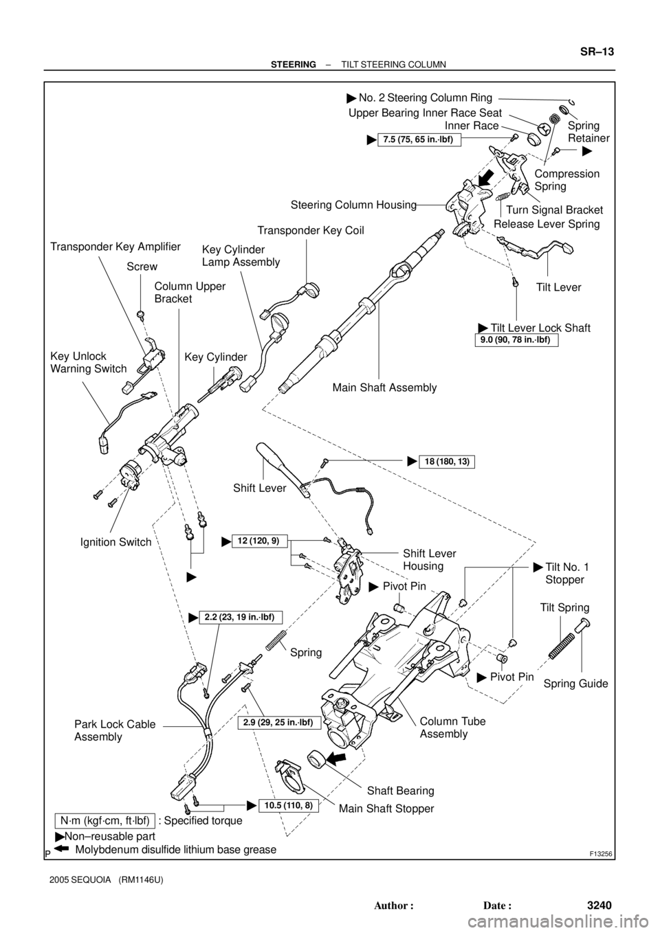
TILT STEERING COLUMN
COMPONENTS
Page 3248 of 4323
F13256
�Non±reusable part
Molybdenum disulfide lithium base grease
: Specified torqueN´m (kgf´cm, ft´lbf)Column Upper
Bracket
Key Cylinder Key Unlock
Warning Switch
Ignition Switch
10.5 (110, 8)�Column Tube
Assembly
2.2 (23, 19 in.´lbf)�
Spring Guide
�
Tilt Spring Main Shaft Assembly Steering Column Housing
Tilt Lever Release Lever SpringTurn Signal Bracket�
Compression
SpringSpring
Retainer Upper Bearing Inner Race Seat
Inner Race
�12 (120, 9)
Pivot Pin
Spring
Park Lock Cable
Assembly
Shaft Bearing
Main Shaft Stopper
Pivot Pin Shift Lever
Housing
18 (180, 13)�� �
Shift Lever
No. 2 Steering Column Ring�
Tilt Lever Lock Shaft9.0 (90, 78 in.´lbf)
�
��
7.5 (75, 65 in.´lbf)
2.9 (29, 25 in.´lbf)
Transponder Key Coil
Key Cylinder
Lamp Assembly
Screw
Transponder Key Amplifier
Tilt No. 1
Stopper
± STEERINGTILT STEERING COLUMN
SR±13
3240 Author�: Date�:
2005 SEQUOIA (RM1146U)
Page 3256 of 4323

SR0V3±05
R12807
Washer
Retaining RingSST
F06735
F06736
± STEERINGTILT STEERING COLUMN
SR±21
3248 Author�: Date�:
2005 SEQUOIA (RM1146U)
REASSEMBLY
NOTICE:
When using a vise, do not overtighten it.
1. COAT PARTS INDICATED BY ARROWS WITH MOLYB-
DENUM DISULFIDE LITHIUM BASE GREASE (See
page SR±12)
2. INSTALL TILT LEVER
Install the tilt lever with a new tilt lever lock shaft.
Torque: 9.0 N´m (90 kgf´cm, 78 in.´lbf)
3. INSTALL MAIN SHAFT ASSEMBLY
(a) Install the inner race, upper bearing inner race seat, com-
pression spring and spring retainer.
(b) Install a new No. 2 steering column ring to the main shaft
assembly.
(c) Install the washer of SST on the main shaft assembly.
SST 09612±07010
(d) Set SST on the main shaft assembly, as shown in the il-
lustration.
SST 09612±07010
(e) Using SST, push down the retaining ring until it fits into the
shaft groove and install the main shaft assembly.
NOTICE:
Do not bend the universal joint of the shaft assembly more
than 15°.
HINT:
Hold the main shaft assembly with your hand to prevent rota-
tion.
4. INSTALL MAIN SHAFT STOPPER
5. INSTALL 2 NEW TILT NO. 1 STOPPERS
6. INSTALL STEERING COLUMN HOUSING WITH MAIN
SHAFT ASSEMBLY
(a) Install the steering column housing with the main shaft as-
sembly into the column tube assembly.
(b) Install the tilt spring and spring guide.
(c) Hold the steering column housing and steering column
housing support in a vise.
(d) Temporarily install 2 new pivot pins.
(e) Using a punch and a hammer, tap in the pivot pin.
(f) Using a pin punch and a hammer, stake at 3 places evenly
around the hole as shown in the illustration.
Page 3257 of 4323

F06737
F13612
SR±22
± STEERINGTILT STEERING COLUMN
3249 Author�: Date�:
2005 SEQUOIA (RM1146U)
7. INSTALL TURN SIGNAL BRACKET
Using a torx® socket wrench, install the turn signal bracket with
2 new torx® screws.
Torque: 7.5 N´m (75 kgf´cm, 65 in.´lbf)
HINT:
Make sure that the protrusion on the steering column housing
is fitted into the hole of the turn signal bracket.
8. INSTALL RELEASE LEVER SPRING
9. INSTALL SHIFT LEVER HOUSING
Using a torx® socket wrench, install the shift lever housing with
3 new torx® screws.
Torque: 12 N´m (120 kgf´cm, 9 ft´lbf)
10. INSTALL PARK LOCK CABLE ASSEMBLY (See page
AT±21)
11. INSTALL SHIFT LEVER
Using a torx® socket wrench, install the shift lever with a new
torx® screw.
Torque: 18 N´m (180 kgf´cm, 13 ft´lbf)
12. INSTALL COLUMN UPPER BRACKET
(a) Install the column upper bracket with 2 new tapered±
head bolts.
HINT:
Insert the bracket pin into the column tube hole.
(b) Tighten the tapered±head bolts until the bolt heads break
off.
13. INSTALL KEY CYLINDER LAMP ASSEMBLY
14. INSTALL TRANSPONDER KEY COIL
Page 3258 of 4323
SR1KE±01
F17897Matchmarks
F17913
Matchmarks
± STEERINGTILT STEERING COLUMN
SR±23
3250 Author�: Date�:
2005 SEQUOIA (RM1146U)
INSTALLATION
NOTICE:
When replacing the steering angle sensor, drive the vehicle
straight ahead at a speed of 6.5 mph (10.5 km/h) or more.
Accordingly, zero point calibration of the steering angle
sensor is performed.
HINT:
If the steering angle sensor zero point calibration is not per-
formed, its value will be fixed. Check after driving the vehicle
straight ahead at a speed of 6.5 mph (10.5 km/h) or more (See
page DI±946).
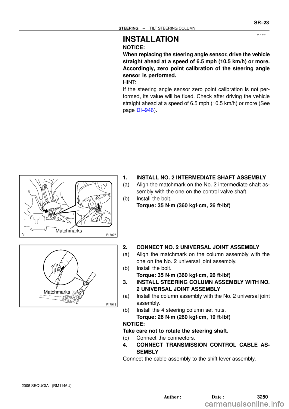
1. INSTALL NO. 2 INTERMEDIATE SHAFT ASSEMBLY
(a) Align the matchmark on the No. 2 intermediate shaft as-
sembly with the one on the control valve shaft.
(b) Install the bolt.
Torque: 35 N´m (360 kgf´cm, 26 ft´lbf)
2. CONNECT NO. 2 UNIVERSAL JOINT ASSEMBLY
(a) Align the matchmark on the column assembly with the
one on the No. 2 universal joint assembly.
(b) Install the bolt.
Torque: 35 N´m (360 kgf´cm, 26 ft´lbf)
3. INSTALL STEERING COLUMN ASSEMBLY WITH NO.
2 UNIVERSAL JOINT ASSEMBLY
(a) Install the column assembly with the No. 2 universal joint
assembly.
(b) Install the 4 steering column set nuts.
Torque: 26 N´m (260 kgf´cm, 19 ft´lbf)
NOTICE:
Take care not to rotate the steering shaft.
(c) Connect the connectors.
4. CONNECT TRANSMISSION CONTROL CABLE AS-
SEMBLY
Connect the cable assembly to the shift lever assembly.
Page 3259 of 4323

F13260
F17896
BMatchmarks
A
F19948
Mark
SR±24
± STEERINGTILT STEERING COLUMN
3251 Author�: Date�:
2005 SEQUOIA (RM1146U)
5. INSTALL COLUMN HOLE COVER NO. 2
Install the column hole cover No. 2 to the body with the 3 bolts.
Torque: 8.0 N´m (82 kgf´cm, 71 in.´lbf)
6. INSTALL SLIDING YOKE
(a) Align the matchmark on the sliding yoke with the one on
the No. 2 intermediate shaft assembly.
(b) Install the ºBº bolt.
Torque: 35 N´m (360 kgf´cm, 26 ft´lbf)
(c) Install the ºAº bolt.
Torque: 35 N´m (360 kgf´cm, 26 ft´lbf)
7. INSTALL BRAKE PEDAL RETURN SPRING
8. INSTALL NO. 2 HEATER TO REGISTER DUCT
9. INSTALL LOWER LH FINISH PANEL
(a) Install the lower LH finish panel with the 4 bolts.
(b) Connect the hood lock release lever with the 2 screws.
10. INSTALL COWL SIDE TRIM AND FRONT DOOR
SCUFF PLATE
11. INSTALL SPIRAL CABLE (See page BE±26)
12. INSTALL COMBINATION SWITCH WITH SPIRAL
CABLE
(a) Install the combination switch with the 3 screws.
(b) Connect the airbag connector.
(c) Connect the 4 connectors.
13. INSTALL UPPER AND LOWER COLUMN COVERS
Install the upper and lower column covers with the 3 screws.
14. CENTER SPIRAL CABLE
(a) Check that the front wheels are facing straight ahead.
(b) Turn the cable counterclockwise by hand until it feels firm.
(c) Then rotate the cable clockwise about 2.5 turns to align
the marks.
HINT:
The cable will rotate about 2.5 turns to both the left and right
from the center.
Page 3260 of 4323
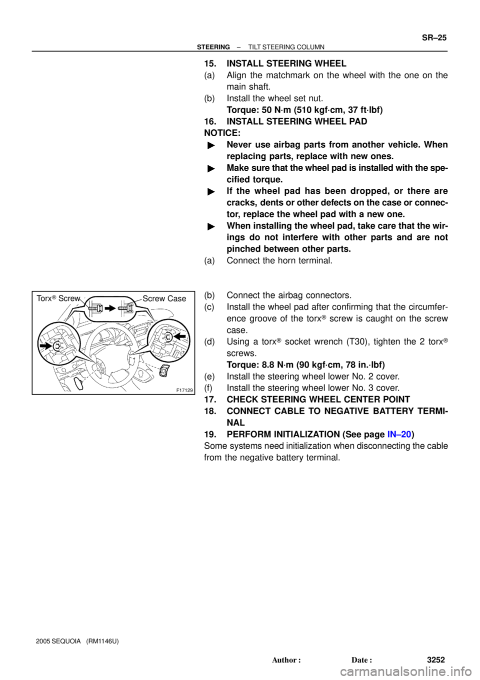
F17129
Torx® Screw
Screw Case
± STEERINGTILT STEERING COLUMN
SR±25
3252 Author�: Date�:
2005 SEQUOIA (RM1146U)
15. INSTALL STEERING WHEEL
(a) Align the matchmark on the wheel with the one on the
main shaft.
(b) Install the wheel set nut.
Torque: 50 N´m (510 kgf´cm, 37 ft´lbf)
16. INSTALL STEERING WHEEL PAD
NOTICE:
�Never use airbag parts from another vehicle. When
replacing parts, replace with new ones.
�Make sure that the wheel pad is installed with the spe-
cified torque.
�If the wheel pad has been dropped, or there are
cracks, dents or other defects on the case or connec-
tor, replace the wheel pad with a new one.
�When installing the wheel pad, take care that the wir-
ings do not interfere with other parts and are not
pinched between other parts.
(a) Connect the horn terminal.
(b) Connect the airbag connectors.
(c) Install the wheel pad after confirming that the circumfer-
ence groove of the torx® screw is caught on the screw
case.
(d) Using a torx® socket wrench (T30), tighten the 2 torx®
screws.
Torque: 8.8 N´m (90 kgf´cm, 78 in.´lbf)
(e) Install the steering wheel lower No. 2 cover.
(f) Install the steering wheel lower No. 3 cover.
17. CHECK STEERING WHEEL CENTER POINT
18. CONNECT CABLE TO NEGATIVE BATTERY TERMI-
NAL
19. PERFORM INITIALIZATION (See page IN±20)
Some systems need initialization when disconnecting the cable
from the negative battery terminal.
Page 3261 of 4323
SR0MD±08
F06723
Air Cleaner Assembly
with Air Cleaner HoseMAF Meter Connector
Clamp
Return Hose
N´m (kgf´cm, ft´lbf) : Specified torque
� Non±reusable part
� Gasket
46.5 (475, 34)Clip
Vacuum Hose
Clip
Drive Belt
PS Vane Pump
Assembly44 (450, 33)
Pressure Feed Tube
22 (220, 16)
SR±26
± STEERINGPOWER STEERING VANE PUMP
3253 Author�: Date�:
2005 SEQUOIA (RM1146U)
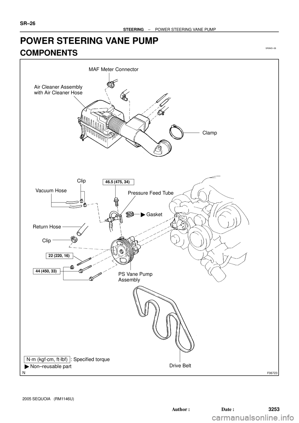
POWER STEERING VANE PUMP
COMPONENTS