Page 2362 of 4323
DIDBP±01
I27727
Instrument Panel J/B
� RAD NO. 2 Fuse
� ECU±B Fuse
� AM1 FuseEngine Room J/B
� RAD NO. 1 Fuse
� RAD NO. 3 Fuse
Steering Pad
Switch
Ignition SwitchDisc Player
Controller
(*1)
Stereo
Component
Amplifier
Multi±display
Controller (*1)
VTR
Terminal
(*1)Headphone
Terminal
(*1) (*2)
Radio and
Navigation Assy GPS Antenna
TweeterTelevision Display Assy (*1)
Rear Seat Audio
Controller Assy (*2)
Rear Door SpeakerRear Door Speaker
Front Door Speaker
and Woofer
Front Door Speaker
and Woofer
*1: w/ RSE System
*2: w/ RSA System
DI±2160
± DIAGNOSTICSNAVIGATION SYSTEM
2354 Author�: Date�:
2005 SEQUOIA (RM1146U)
LOCATION
Page 2363 of 4323
DIDBQ±01
I28761
Radio
and
Navigation
Assy Steering Pad Switch
Stereo
Component
Amplifier
AssyVehicle Speed Signal
Reverse Signal
GPS Antenna
AVC±LAN Park/Neutral Position Switch Combination Meter
Speakers
Display Signal Sound SignalMulti±display
Controller
Assy (*1)
Rear Seat
Audio
Controller
(*2) *1: w/ RSE System
*2: w/ RSA System(*1)
± DIAGNOSTICSNAVIGATION SYSTEM
DI±2161
2355 Author�: Date�:
2005 SEQUOIA (RM1146U)
SYSTEM DIAGRAM
Page 2367 of 4323

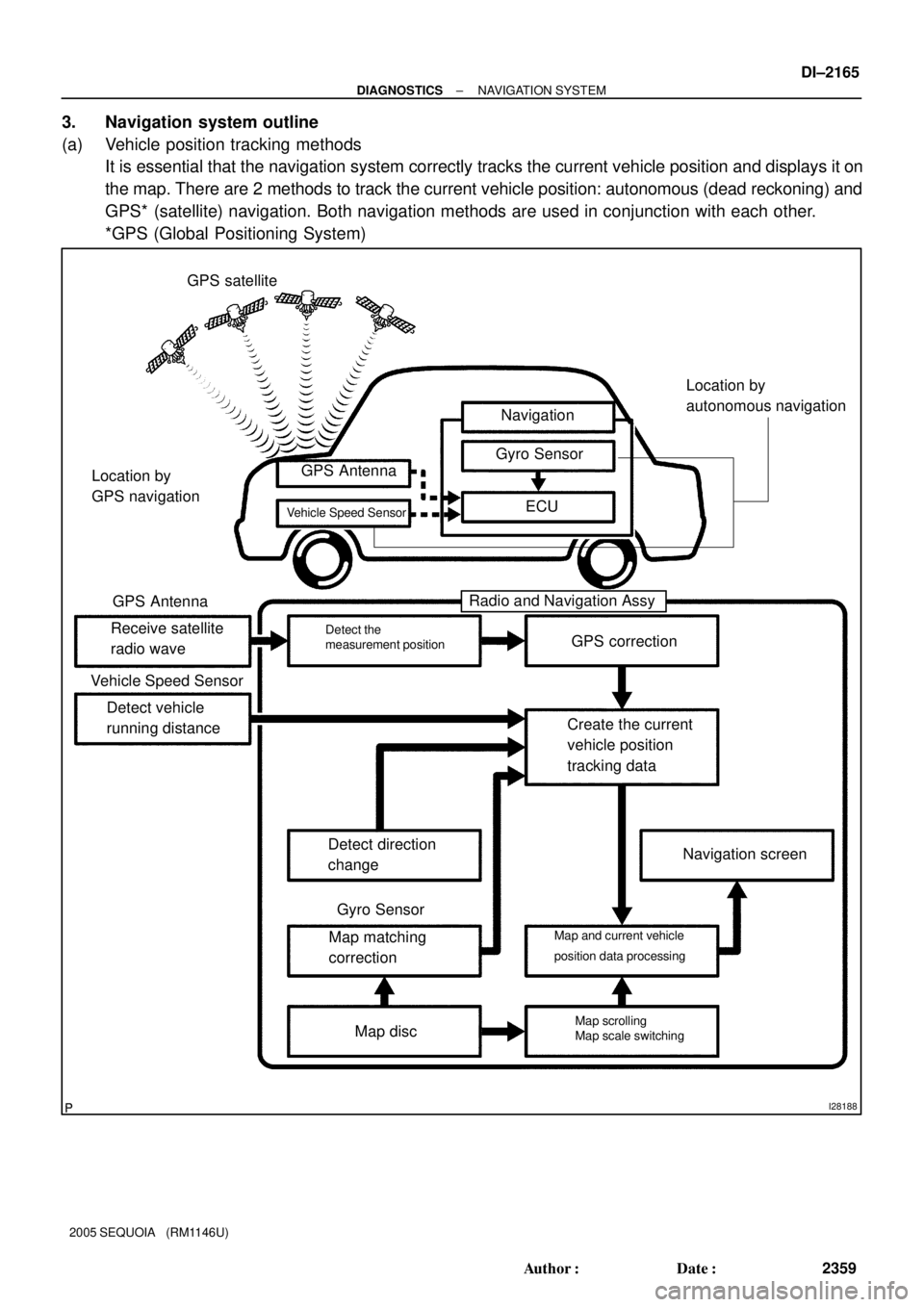
I28188
GPS satellite
Navigation
Gyro Sensor
ECU GPS Antenna
Receive satellite
radio waveGPS correction
Create the current
vehicle position
tracking data
Navigation screen
Map disc Map matching
correction Detect direction
change Detect vehicle
running distance
Radio and Navigation Assy
Detect the
measurement position
Map scrolling
Map scale switching Map and current vehicle
position data processing Vehicle Speed Sensor
GPS Antenna
Vehicle Speed SensorLocation by
GPS navigation
Gyro Sensor
Location by
autonomous navigation
± DIAGNOSTICSNAVIGATION SYSTEM
DI±2165
2359 Author�: Date�:
2005 SEQUOIA (RM1146U)
3. Navigation system outline
(a) Vehicle position tracking methods
It is essential that the navigation system correctly tracks the current vehicle position and displays it on
the map. There are 2 methods to track the current vehicle position: autonomous (dead reckoning) and
GPS* (satellite) navigation. Both navigation methods are used in conjunction with each other.
*GPS (Global Positioning System)
Page 2387 of 4323

± DIAGNOSTICSNAVIGATION SYSTEM
DI±2185
2379 Author�: Date�:
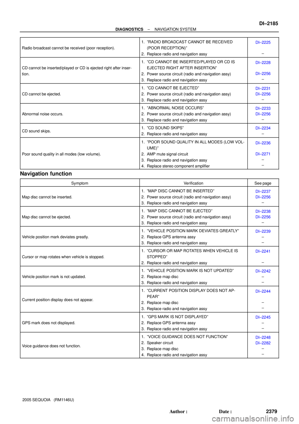
2005 SEQUOIA (RM1146U) Radio broadcast cannot be received (poor reception).
1. ºRADIO BROADCAST CANNOT BE RECEIVED
(POOR RECEPTION)º
2. Replace radio and navigation assyDI±2225
±
CD cannot be inserted/played or CD is ejected right after inser-
tion.
1. ºCD CANNOT BE INSERTED/PLAYED OR CD IS
EJECTED RIGHT AFTER INSERTIONº
2. Power source circuit (radio and navigation assy)
3. Replace radio and navigation assyDI±2228
DI±2256
±
CD cannot be ejected.
1. ºCD CANNOT BE EJECTEDº
2. Power source circuit (radio and navigation assy)
3. Replace radio and navigation assyDI±2231
DI±2256
±
Abnormal noise occurs.
1. ºABNORMAL NOISE OCCURSº
2. Power source circuit (radio and navigation assy)
3. Replace radio and navigation assyDI±2233
DI±2256
±
CD sound skips.1. ºCD SOUND SKIPSº
2. Replace radio and navigation assyDI±2234
±
Poor sound quality in all modes (low volume).
1. ºPOOR SOUND QUALITY IN ALL MODES (LOW VOL-
UME)º
2. AMP mute signal circuit
3. Replace radio and navigation assy
4. Replace stereo component amplifierDI±2236
DI±2271
±
±
Navigation function
SymptomVerificationSee page
Map disc cannot be inserted.
1. ºMAP DISC CANNOT BE INSERTEDº
2. Power source circuit (radio and navigation assy)
3. Replace radio and navigation assyDI±2237
DI±2256
±
Map disc cannot be ejected.
1. ºMAP DISC CANNOT BE EJECTEDº
2. Power source circuit (radio and navigation assy)
3. Replace radio and navigation assyDI±2238
DI±2256
±
Vehicle position mark deviates greatly.
1. ºVEHICLE POSITION MARK DEVIATES GREATLYº
2. Replace GPS antenna assy
3. Replace radio and navigation assyDI±2239
±
±
Cursor or map rotates when vehicle is stopped.
1. ºCURSOR OR MAP ROTATES WHEN VEHICLE IS
STOPPEDº
2. Replace radio and navigation assyDI±2241
±
Vehicle position mark is not updated.
1. ºVEHICLE POSITION MARK IS NOT UPDATEDº
2. Replace map disc
3. Replace radio and navigation assyDI±2242
±
±
Current position display does not appear.
1. ºCURRENT POSITION DISPLAY DOES NOT AP-
PEARº
2. Replace map disc
3. Replace radio and navigation assyDI±2244
±
±
GPS mark does not displayed.
1. ºGPS MARK IS NOT DISPLAYEDº
2. Replace GPS antenna assy
3. Replace radio and navigation assyDI±2245
±
±
Voice guidance does not function.
1. ºVOICE GUIDANCE DOES NOT FUNCTIONº
2. Speaker circuit
3. Replace map disc
4. Replace radio and navigation assyDI±2248
DI±2282
±
±
Page 2389 of 4323

DIDC4±01
I28763
R27
R29R30
R26R28
± DIAGNOSTICSNAVIGATION SYSTEM
DI±2187
2381 Author�: Date�:
2005 SEQUOIA (RM1146U)
TERMINALS OF ECU
1. RADIO AND NAVIGATION ASSY
Symbols (Terminal No.)Wiring ColorTerminal DescriptionConditionSpecification
ACC (R30±11) ±
GND (R30±20)GR ± BRAccessory (ON)Ignition switch OFF
"ACC or ONBelow 1 V "10 to 14 V
B (R30±1) ± GND (R30±20)L±Y ± BRBatteryAlways10 to 14 V
GND (R30±20) ± Body groundBR ±
Body groundGroundAlwaysBelow 1 V
ANT (R30±13) ±
GND (R30±20)B±R ± BRPower source of antennaRadio switch ON and AM or FM10 to 14 V
ILL+ (R30±2) ± ILL± (R30±12)G ± W±GIllumination signal
Ignition switch ON
Light control switch OFF "TAIL or
ONBelow 1 V "
10 to 14 V
R+ (R30±8) ± GND (R30±20)W ± BRSound signal (Right)Audio system is playing
A waveform synchro-
nized with sound is out-
put
L+ (R30±9) ± GND (R30±20)B ± BRSound signal (Left)Audio system is playing
A waveform synchro-
nized with sound is out-
put
R± (R30±18) ± GND (R30±20)G ± BRSound signal (Right)Audio system is playing
A waveform synchro-
nized with sound is out-
put
L± (R30±19) ± GND (R30±20)R ± BRSound signal (Left)Audio system is playing
A waveform synchro-
nized with sound is out-
put
SWG (R27±6) ± Body groundBR±W ±
Body groundSteering pad switch
groundAlwaysBelow 1 V
SW1 (R27±7) ± SWG (R27±6)LG±R ± BR±WSteering pad switch signal
Steering pad switch not operated
"SEEK+ switch pushed
"SEEK± switch pushed
"VOL+ switch pushed
"VOL± switch pushed4 V or more
"Approx. 0.5 V
"Approx. 0.9 V
"Approx. 2.0 V
"Approx. 3.4 V
Page 2427 of 4323
± DIAGNOSTICSNAVIGATION SYSTEM
DI±2225
2419 Author�: Date�:
2005 SEQUOIA (RM1146U)
Radio broadcast cannot be received (Poor reception)
INSPECTION PROCEDURE
1 Check if radio auto±search functions properly.
CHECK:
Check if the radio auto±search functions properly.
Perform the auto±search of the radio and check that it functions normally.
OK:
The radio auto±search functions properly.
OK Replace radio and navigation assy.
NG
2 Check optional components.
CHECK:
Check optional component (sun shade film, telephone antenna, etc.).
Check whether or not any optional component such as the sun shade film and the telephone antenna
is installed.
OK:
Optional component is not installed.
NG Effect from optional component.
OK
DIDCK±01
Page 2428 of 4323
I28255
DI±2226
± DIAGNOSTICSNAVIGATION SYSTEM
2420 Author�: Date�:
2005 SEQUOIA (RM1146U)
3 Inspect radio and navigation assy.
PREPARATION:
Remove the antenna plug from the radio and navigation assy.
CHECK:
With the radio and navigation assy connector connected, turn
the ignition switch to the ACC position.
Turn on the radio and choose the AM mode.
Place a screwdriver or a piece of metal such as thin wire on an
antenna jack of the radio and navigation assy and check that
the noise is heard from the speaker.
OK:
Noise occurs.
NG Replace radio and navigation assy.
OK
4 Check antenna assy.
CHECK:
Check that the antenna is securely installed.
OK:
The antenna is installed properly.
NG Install antenna assy properly.
OK
Page 2429 of 4323
± DIAGNOSTICSNAVIGATION SYSTEM
DI±2227
2421 Author�: Date�:
2005 SEQUOIA (RM1146U)
5 Check antenna cord sub±assy.
PREPARATION:
Remove the antenna plug of the radio and navigation assy and antenna assy.
CHECK:
Measure the resistance between the antenna assy and radio and navigation assy to check for an open circuit
in the antenna cord sub±assy.
OK:
Below 1 W
CHECK:
Measure the resistance between the antenna cord sub±assy and body ground to check for a short circuit
in the antenna cord sub±assy.
OK:
10 kW or higher
NG Replace antenna cord sub±assy.
OK
6 Replace amplifier antenna assy.
CHECK:
Replace the amplifier antenna assy and check if it operates normally.
OK:
The amplifier antenna assy operates normally.
OK Normal operation.
NG
Proceed to next circuit inspection shown in problem symptoms table (See page DI±2184).