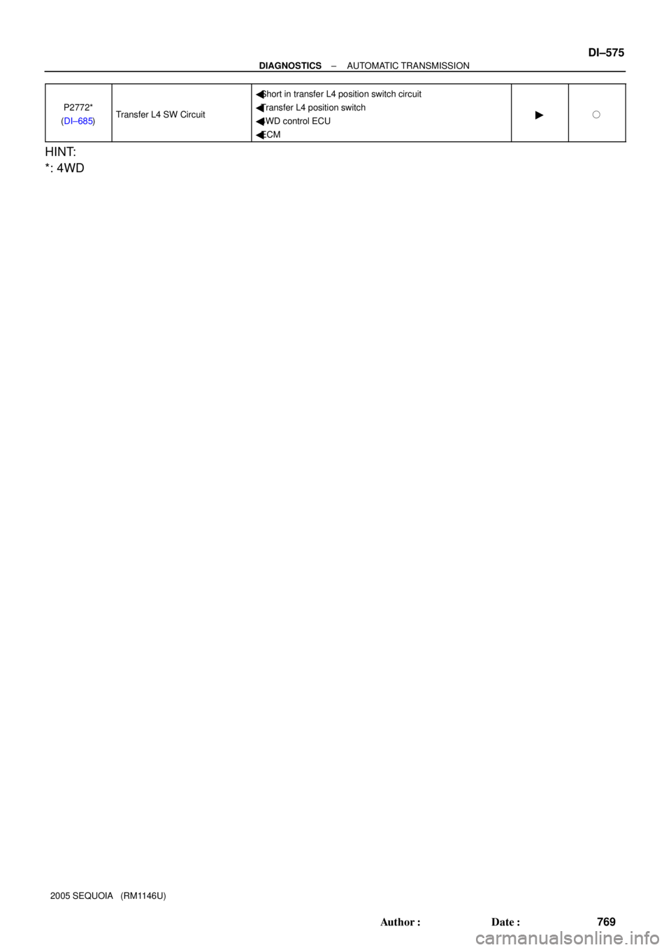
Page 721 of 4323
DIDIK±01
D13871
Combination Meter
DLC3 Stop Light SwitchECM
Park/Neutral Position SwitchSpeed Sensor (SP2) Shift Solenoid Valve S1
Shift Solenoid Valve SR
Shift Solenoid Valve SLU
Shift Solenoid Valve SL2 ATF Temperature
Sensor No. 2Integration Control and Panel
(Shift Position L Switch) � MIL
Shift Solenoid Valve SL1
Shift Solenoid
Valve SLT
ATF Temperature
Sensor No.1
Shift Solenoid Valve S2
Speed Sensor (NT)
� AT Oil Temp Warning LightShift Lever
(O/D Main Switch)
4WD:
4WD Control ECU
± DIAGNOSTICSAUTOMATIC TRANSMISSION
DI±519
713 Author�: Date�:
2005 SEQUOIA (RM1146U)
LOCATION
Page 722 of 4323

DIDIL±01
D14205
Shift Solenoid Valve S1
MIL
(Malfunction Indicator Lamp) S1
S2
SL1
SL2
SLT
SLU
SR
WShift Solenoid Valve S2
Shift Solenoid Valve SL1
Shift Solenoid Valve SL2
Shift Solenoid Valve SLT
Shift Solenoid Valve SLU
Shift Solenoid Valve SR
OILW
AT Oil Temp Warning Light ECM Crankshaft Position Sensor
Engine CoolantTemperature Sensor
Combination Meter
Stop Lamp Switch Assy
DLC3
(Data Link Connector 3)THW VTA1, 2
VC
SPD
STPTH01
TC Throttle Position Sensor
ATF (Automatic Transmission
Fluid) Temperature Sensor No. 1Mass Air Flow Meter
Accelerator Pedal Position SensorVPA
VPA2
Shift Lever
(O/D Main Switch)
Input Speed Sensor (NT)NT
Output Speed Sensor (SP2)SP2
TH02
ATF (Automatic Transmission
Fluid) Temperature Sensor No. 2Skid Control ECUNSW
Park/Neutral Position Switch
R, D, 3, 2
VG
NE
L
ODMSIntegration Control and Panel
(Shift Position L Switch)
L4
�
�: 4WD4WD Control ECU
CAN DI±520
± DIAGNOSTICSAUTOMATIC TRANSMISSION
714 Author�: Date�:
2005 SEQUOIA (RM1146U)
SYSTEM DIAGRAM
The configuration of the electronic control system in the A750E/A750F automatic transmission is as shown
in the following chart.
Page 762 of 4323
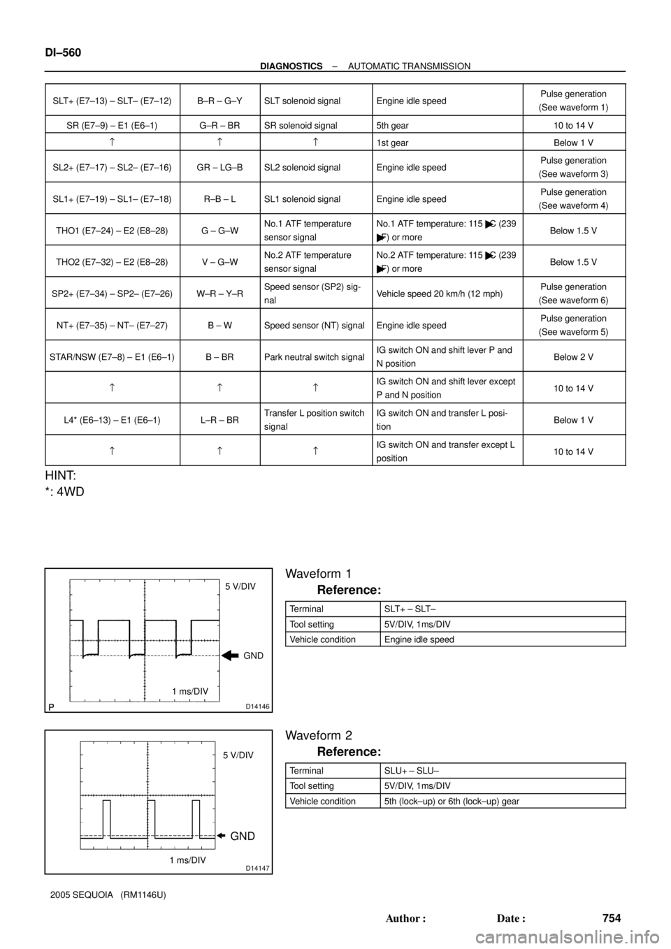
D14146
5 V/DIV
1 ms/DIVGND
D14147
GND
5 V/DIV
1 ms/DIV
DI±560
± DIAGNOSTICSAUTOMATIC TRANSMISSION
754 Author�: Date�:
2005 SEQUOIA (RM1146U)SLT+ (E7±13) ± SLT± (E7±12)
B±R ± G±YSLT solenoid signalEngine idle speedPulse generation
(See waveform 1)
SR (E7±9) ± E1 (E6±1)G±R ± BRSR solenoid signal5th gear10 to 14 V
===1st gearBelow 1 V
SL2+ (E7±17) ± SL2± (E7±16)GR ± LG±BSL2 solenoid signalEngine idle speedPulse generation
(See waveform 3)
SL1+ (E7±19) ± SL1± (E7±18)R±B ± LSL1 solenoid signalEngine idle speedPulse generation
(See waveform 4)
THO1 (E7±24) ± E2 (E8±28)G ± G±WNo.1 ATF temperature
sensor signalNo.1 ATF temperature: 115 �C (239
�F) or moreBelow 1.5 V
THO2 (E7±32) ± E2 (E8±28)V ± G±WNo.2 ATF temperature
sensor signalNo.2 ATF temperature: 115 �C (239
�F) or moreBelow 1.5 V
SP2+ (E7±34) ± SP2± (E7±26)W±R ± Y±RSpeed sensor (SP2) sig-
nalVehicle speed 20 km/h (12 mph)Pulse generation
(See waveform 6)
NT+ (E7±35) ± NT± (E7±27)B ± WSpeed sensor (NT) signalEngine idle speedPulse generation
(See waveform 5)
STAR/NSW (E7±8) ± E1 (E6±1)B ± BRPark neutral switch signalIG switch ON and shift lever P and
N positionBelow 2 V
===IG switch ON and shift lever except
P and N position10 to 14 V
L4* (E6±13) ± E1 (E6±1)L±R ± BRTransfer L position switch
signalIG switch ON and transfer L posi-
tionBelow 1 V
===IG switch ON and transfer except L
position10 to 14 V
HINT:
*: 4WD
Waveform 1
Reference:
TerminalSLT+ ± SLT±
Tool setting5V/DIV, 1ms/DIV
Vehicle conditionEngine idle speed
Waveform 2
Reference:
TerminalSLU+ ± SLU±
Tool setting5V/DIV, 1ms/DIV
Vehicle condition5th (lock±up) or 6th (lock±up) gear
Page 777 of 4323
± DIAGNOSTICSAUTOMATIC TRANSMISSION
DI±575
769 Author�: Date�:
2005 SEQUOIA (RM1146U)P2772*
(DI±685)
Transfer L4 SW Circuit
�Short in transfer L4 position switch circuit
�Transfer L4 position switch
�4WD control ECU
�ECM
��
HINT:
*: 4WD
Page 780 of 4323
D14218
ECM
R
D
2 3 E78
STAR/NSW
11
E5
E521
E519
E510 J52
J52
J52
J52
J52
J52 J/C
J51
J51
J51
J51
J51
J51B
L±Y
B±Y
W±R
L
LG LGL W±RB±YL±Y
L±R
L±R
B±Y W±L
W BG±R* G±R P
PL
RL
NL
DL
2L
LL IG49
1D 1C
IPOGAUGE
IG1
AM1 74
8
7
1C
1L16AM1
2 1 ALT
BatteryF10
FL BlockCowl Side J/B LHI18
Ignition SW Cowl Side J/B RHTo 4WD Control ECU
To Translate ECU To Starter RelayP1
Park/Neutral Position SW
*: 4WD 21 N
8 54
5
6
1
9
7
3
8AEG GF HA H
C C
F
E
2
RB DI±578
± DIAGNOSTICSAUTOMATIC TRANSMISSION
772 Author�: Date�:
2005 SEQUOIA (RM1146U)
WIRING DIAGRAM
Page 798 of 4323
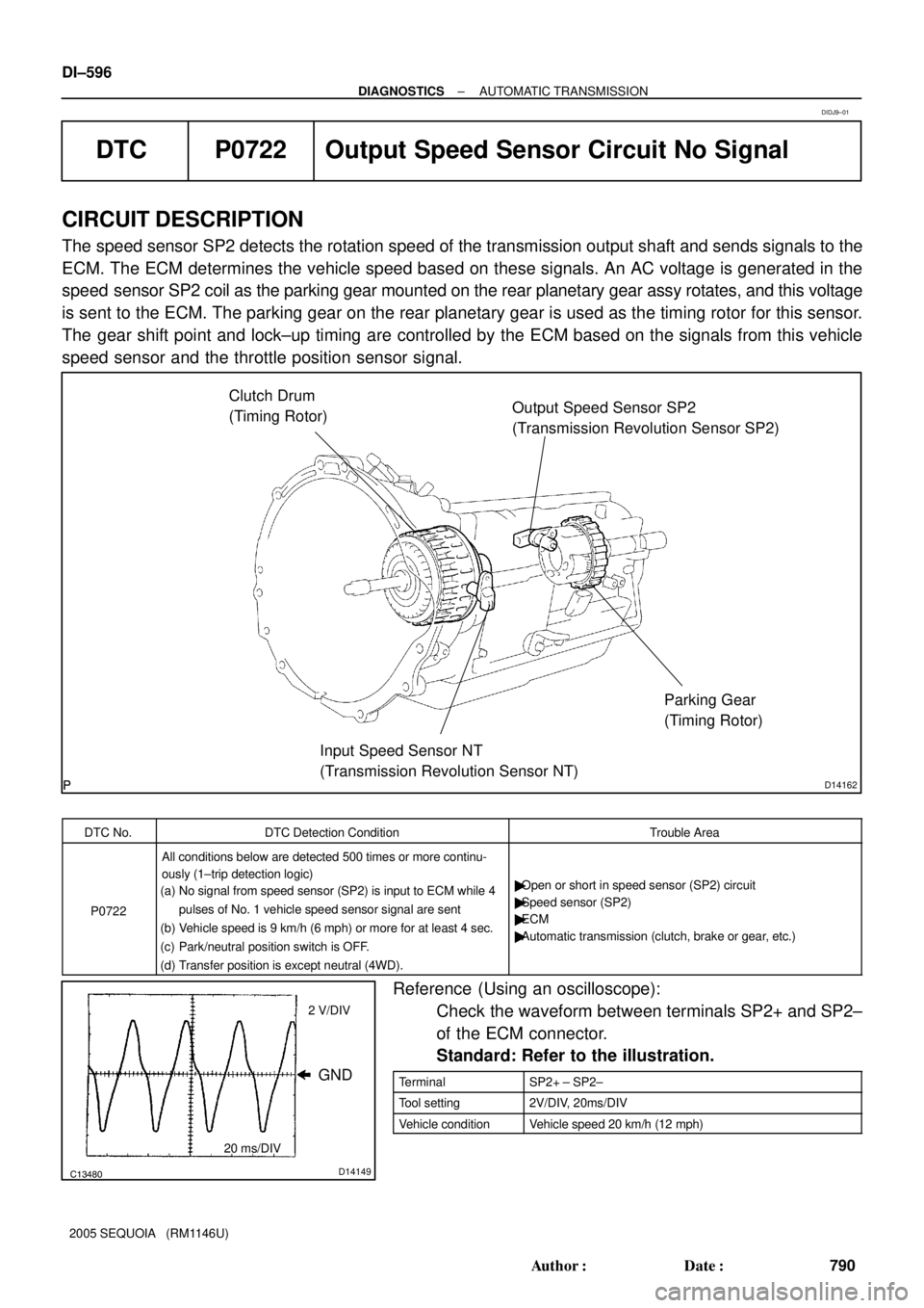
D14162
Clutch Drum
(Timing Rotor)
Input Speed Sensor NT
(Transmission Revolution Sensor NT)Output Speed Sensor SP2
(Transmission Revolution Sensor SP2)
Parking Gear
(Timing Rotor)
C13480D14149
GND
2 V/DIV
20 ms/DIV
DI±596
± DIAGNOSTICSAUTOMATIC TRANSMISSION
790 Author�: Date�:
2005 SEQUOIA (RM1146U)
DTC P0722 Output Speed Sensor Circuit No Signal
CIRCUIT DESCRIPTION
The speed sensor SP2 detects the rotation speed of the transmission output shaft and sends signals to the
ECM. The ECM determines the vehicle speed based on these signals. An AC voltage is generated in the
speed sensor SP2 coil as the parking gear mounted on the rear planetary gear assy rotates, and this voltage
is sent to the ECM. The parking gear on the rear planetary gear is used as the timing rotor for this sensor.
The gear shift point and lock±up timing are controlled by the ECM based on the signals from this vehicle
speed sensor and the throttle position sensor signal.
DTC No.DTC Detection ConditionTrouble Area
P0722
All conditions below are detected 500 times or more continu-
ously (1±trip detection logic)
(a) No signal from speed sensor (SP2) is input to ECM while 4
pulses of No. 1 vehicle speed sensor signal are sent
(b) Vehicle speed is 9 km/h (6 mph) or more for at least 4 sec.
(c) Park/neutral position switch is OFF.
(d) Transfer position is except neutral (4WD).
�Open or short in speed sensor (SP2) circuit
�Speed sensor (SP2)
�ECM
�Automatic transmission (clutch, brake or gear, etc.)
Reference (Using an oscilloscope):
Check the waveform between terminals SP2+ and SP2±
of the ECM connector.
Standard: Refer to the illustration.
TerminalSP2+ ± SP2±
Tool setting2V/DIV, 20ms/DIV
Vehicle conditionVehicle speed 20 km/h (12 mph)
DIDJ9±01
Page 811 of 4323

± DIAGNOSTICSAUTOMATIC TRANSMISSION
DI±609
803 Author�: Date�:
2005 SEQUOIA (RM1146U) Shift solenoid valve SL2 circuit
Not circuit malfunction
ECT (Engine coolant temperature) sensor
circuitNot circuit malfunction
KCS sensor circuitNot circuit malfunction
ETCS (Electric throttle control system)Not system down
Transmission rangeºDº
ECT40°C (104°F) or more±
Spark advance from Max. retard timing by
KCS control0° CA or more±
EngineStarting
Transfer rangeºHIGHº*1
Transfer range ºHIGHº *1 (This condition is applied only 4WD)
*1 Following conditions met
Vehicle speed sensor circuitNot circuit malfunction
Output shaft speed sensor circuitNot circuit malfunction
Transfer output speed143 rpm or more±
NO/NOtf (Transfer input speed/Transfer
output speed)0.9 to 1.1
OFF malfunction (A)
ECM selected gear1st
Vehicle speed2 to 40 km/h (1.2 to 24.9 mph)
Throttle valve opening angle
8% or more
and 7.0% or more at 2,000 rpm
(Conditions vary with engine speed)
±
OFF malfunction (B)
Current ECM selected gear5th
Last ECM selected gear4th
Continuous time for ECM selecting 4th
gear2 sec. or more±
Actual gear when ECM selected 4th gear4th
OFF malfunction (C)
Current ECM selected gear5th
Last ECM selected gear4th
ON malfunction (A)
ECM selected gear1st
Vehicle speed2 to 40 km/h (1.2 to 24.9 mph)
Throttle valve opening angle7.0% or more at 2,000 rpm
(Conditions vary with engine speed)±
ON malfunction (B)
ECM selected gear4th
Vehicle speed2 km/h (1.2 mph) or more±
Throttle valve opening angle7.0% or more at 2,000 rpm
(Conditions vary with engine speed)±
ON malfunction (C)
ECM selected gear3rd
Vehicle speed2 km/h (1.2 mph) or more±
Page 817 of 4323

± DIAGNOSTICSAUTOMATIC TRANSMISSION
DI±615
809 Author�: Date�:
2005 SEQUOIA (RM1146U)
TYPICAL ENABLING CONDITIONS
ItSpecificationItemMinimumMaximum
All:
Turbine speed sensor circuitNot circuit malfunction
Output speed sensor circuitNot circuit malfunction
Shift solenoid valve S1 circuitNot circuit malfunction
Shift solenoid valve S2 circuitNot circuit malfunction
Shift solenoid valve SR circuitNot circuit malfunction
Shift solenoid valve SL1 circuitNot circuit malfunction
Shift solenoid valve SL2 circuitNot circuit malfunction
ECT (Engine coolant temperature) sensor
circuitNot circuit malfunction
KCS sensor circuitNot circuit malfunction
ETCS (Electric throttle control system)Not system down
Transmission rangeºDº
ECT40°C (104°F) or more±
Spark advance from Max. retard timing by
KCS control0° CA or more±
EngineStarting
Transfer rangeºHIGHº*1
Transfer range ºHIGHº *1 (This condition is applied only 4WD)
*1 Following conditions met
Vehicle speed sensor circuitNot circuit malfunction
Output shaft speed sensor circuitNot circuit malfunction
Transfer output speed143 rpm or more±
NO/NOtf (Transfer input speed/Transfer
output speed)0.9 to 1.1
OFF malfunction (A)
ECM selected gear1st
Vehicle speed2 to 40 km/h (1.2 to 24.9 mph)
Throttle valve opening angle7.0% or more at 2,000 rpm
(Conditions vary with engine speed)±
OFF malfunction (B)
ECM selected gear2nd
Vehicle speed2 km/h (1.2 mph) or more±
Output speed2nd " 1st down shift point or more±
Throttle valve opening angle7.0% or more at 2,000 rpm
(Conditions vary with engine speed)±
OFF malfunction (C)
Current ECM selected gear5th
Last ECM selected gear4th
Continuous time for ECM selecting 4th
gear2 sec. or more±
Actual gear when ECM selected 4th gear4th
OFF malfunction (D)
Current ECM selected gear5th