Page 3169 of 4323
SA0L4±05
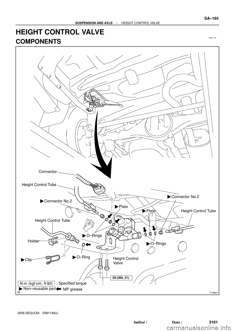
F16841
N´m (kgf´cm, ft´lbf): Specified torque
� Non±reusable part
29 (300, 21)
Connector
Height Control Tube
Height Control Tube
Holder
Clip ��O±RingHeight Control Tube Plate � Plate � Connector No.2 �
�O±Rings
�O±Rings
Height Control
Valve
MP grease
Connector No.2 �
± SUSPENSION AND AXLEHEIGHT CONTROL VALVE
SA±165
3161 Author�: Date�:
2005 SEQUOIA (RM1146U)
HEIGHT CONTROL VALVE
COMPONENTS
Page 3170 of 4323

REMOVAL
1. DISCONNECT HEIGHT CONTROL TUBE
(a) When disconnecting th")
SA2D2±01
F16832
C
BA
F16833
F16834
SA±166
± SUSPENSION AND AXLEHEIGHT CONTROL VALVE
3162 Author�: Date�:
2005 SEQUOIA (RM1146U)
REMOVAL
1. DISCONNECT HEIGHT CONTROL TUBE
(a) When disconnecting the height control tube A:
(1) Remove the clip and holder.
(2) Using SST, disconnect the height control tube.
SST 09730±00010
(3) Remove the O±ring from the height control tube.
HINT:
Perform the following before installation:
�Coat a new O±ring with MP grease.
�Push the air tube in straight to connect it until the clip
makes a ºclickingº sound.
(b) When disconnecting the height control tubes B and C:
NOTICE:
Be careful when removing tube as it will cause air to be re-
leased from the pneumatic cylinder and vehicle height to
decrease. When using a jack or two±post lift, read the op-
eration procedures and precautions for the pneumatic cyl-
inder to prevent damaging the cylinder.
(1) Spread the clip and slowly pull the 2 height control
tubes straight out.
(2) Remove the 4 O±rings, 2 plates, and 2 connector
No.2 from the height control tube.
HINT:
Perform the following before installation:
�Coat 4 new O±rings with MP grease.
2. DISCONNECT CONNECTOR
3. REMOVE HEIGHT CONTROL VALVE
(a) Remove the 2 bolts and height control valve.
Torque: 29 N´m (300 kgf´cm, 21 ft´lbf)
Page 3171 of 4323
SA0L6±03
± SUSPENSION AND AXLEHEIGHT CONTROL VALVE
SA±167
3163 Author�: Date�:
2005 SEQUOIA (RM1146U)
INSTALLATION
Installation is in the reverse order of removal (See page SA±166).
Page 3172 of 4323
SA1I9±03
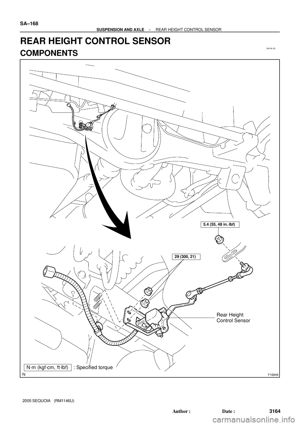
F16849
N´m (kgf´cm, ft´lbf) : Specified torque
29 (300, 21)
5.4 (55, 48 in.´lbf)
Rear Height
Control Sensor
SA±168
± SUSPENSION AND AXLEREAR HEIGHT CONTROL SENSOR
3164 Author�: Date�:
2005 SEQUOIA (RM1146U)
REAR HEIGHT CONTROL SENSOR
COMPONENTS
Page 3173 of 4323
SA2D3±01
F16835Matchmarks
F16836
± SUSPENSION AND AXLEREAR HEIGHT CONTROL SENSOR
SA±169
3165 Author�: Date�:
2005 SEQUOIA (RM1146U)
REMOVAL
1. DISCONNECT CONNECTOR
2. DISCONNECT HEIGHT CONTROL SENSOR LINK
(a) Put matchmarks on the height control sensor link and
bracket.
(b) Remove the nut and disconnect the sensor link.
Torque: 5.4 N´m (55 kgf´cm, 48 in.´lbf)
3. REMOVE REAR HEIGHT CONTROL SENSOR
(a) Disconnect the wire harness clamp.
(b) Remove the 2 bolts and rear height control sensor.
Torque: 29 N´m (300 kgf´cm, 21 ft´lbf)
Page 3174 of 4323
SA1IB±03
SA±170
± SUSPENSION AND AXLEREAR HEIGHT CONTROL SENSOR
3166 Author�: Date�:
2005 SEQUOIA (RM1146U)
INSTALLATION
Installation is in the reverse order of removal (See page SA±169).
Page 3181 of 4323

BRAKE PEDAL
ON±VEHICLE INSPECTION
1. CHECK PEDAL HEIGHT
Pedal hei")
F07754
Pedal Height Push Rod
BR107±04
R00085
Pedal Free Play BR±6
± BRAKEBRAKE PEDAL
3173 Author�: Date�:
2005 SEQUOIA (RM1146U)
BRAKE PEDAL
ON±VEHICLE INSPECTION
1. CHECK PEDAL HEIGHT
Pedal height from dash panel:
151.1 ± 165.1 mm (5.949 ± 6.500 in.)
NOTICE:
Do not adjust the pedal height. Doing so by changing the
push rod length of the brake booster will structurally
change the pedal ratio.
If the pedal height is incorrect, check that there is no damage
in brake pedal, brake pedal lever, brake pedal bracket and dash
panel.
�Even if there is damage, there is no problem if the
reserve distance is within the standard value.
�If necessary, replace them.
2. IF NECESSARY, ADJUST STOP LIGHT SWITCH
(a) Remove the front door scuff plate, cowl side trim, side
panel, lower finish panel and No. 2 heater to register duct
(See page BO±89).
(b) Loosen the stop light switch lock nut.
(c) Push the brake pedal in 5 ± 15 mm (0.20 ± 0.59 in.), turn
the stop light switch to lock the nut in the position where
the stop light goes off.
(d) Push the brake pedal in 5 ±15 mm (0.20 ± 0.59 in.), check
that the stop light lights up.
(e) Install the No. 2 heater to register duct, lower finish panel,
side panel, cowl side trim and front door scuff plate (See
page BO±89).
3. CHECK PEDAL FREE PLAY
(a) Stop the engine and depress the brake pedal several
times until there is no more vacuum left in the booster.
(b) Push in the pedal by hand until the second point of resis-
tance begins to be felt, then measure the distance as
shown in the illustration.
Pedal free play: 1 ± 6 mm (0.04 ± 0.24 in.)
HINT:
The free play to the first point of resistance is due to the play
between the clevis and pin. It is 1 ± 3 mm (0.04 ± 0.12 in.) at the
pedal.
If incorrect, check the stop light switch clearance. If the clear-
ance is OK, then troubleshoot the brake system.
Stop light switch clearance:
0.5 ± 2.4 mm (0.020 ± 0.095 in.)
Page 3265 of 4323
SR0RF±05
F06719
Vane Pump Shaft
Front HousingBushing
N00372
HeightThickness
Length
R10282
Feeler Gauge
SR±30
± STEERINGPOWER STEERING VANE PUMP
3257 Author�: Date�:
2005 SEQUOIA (RM1146U)
INSPECTION
1. CHECK OIL CLEARANCE BETWEEN VANE PUMP
SHAFT AND BUSHING
Using a micrometer and caliper gauge, measure the oil clear-
ance.
Standard clearance:
0.03 to 0.05 mm (0.0012 to 0.0020 in.)
Maximum clearance: 0.07 mm (0.0028 in.)
If it is more than the maximum, replace the shaft and front hous-
ing.
2. INSPECT VANE PUMP ROTOR AND VANE PLATES
(a) Using a micrometer, measure the height, thickness and
length of the 10 plates.
Minimum height: 8.6 mm (0.339 in.)
Minimum thickness: 1.397 mm (0.0550 in.)
Minimum length: 14.991 mm (0.5902 in.)
(b) Using a feeler gauge, measure the clearance between
the rotor groove and plate.
Maximum clearance: 0.033 mm (0.0013 in.)