Page 1834 of 4323
I28558
C612
W±B
Battery AW
58BR
IECombination Meter
W±L I18
Ignition SW
2 1
AM1 IG1
B±Y
W Instrument Panel J/B
AM1
21 47
6 1 6
9 1C
1C
1D 1E
1L
1FR±L
R±LSub J/B No. 3
3B 3A515C524
C610 R±L
Y±RY
Y±RY
13
23 19
26
IG4
IG4
IG4
GAUGE
B V1
Vehicle Speed Sensor
(Combination Meter)
F10
Fusible Link Block
J8
J/C DI±1632
± DIAGNOSTICSCOMBINATION METER SYSTEM
1826 Author�: Date�:
2005 SEQUOIA (RM1146U)
Malfunction in speedometer
CIRCUIT DESCRIPTION
The speedometer detects vehicle speed based on a 4±pulse signal from the vehicle speed sensor.
WIRING DIAGRAM
DID8Z±01
Page 1836 of 4323
N02332
1
2 3
DI±1634
± DIAGNOSTICSCOMBINATION METER SYSTEM
1828 Author�: Date�:
2005 SEQUOIA (RM1146U)
3 Inspect vehicle speed sensor.
PREPARATION:
(a) Disconnect the vehicle speed sensor connector.
(b) Connect the positive (+) lead from the battery to terminal
1 and the negative (±) lead to terminal 2.
(c) Connect the positive (+) lead from the tester to terminal
3 and the negative (±) lead to terminal 2.
(d) Rotate the shaft.
CHECK:
Check that voltage between terminals 2 and 3 changes from
approx. 0 V to16 V or more.
OK:
Voltage changes from approx. 0 V to 16 V
HINT:
The voltage should change 4 times for every revolution of the
speed sensor shaft.
NG Replace vehicle speed sensor.
OK
Page 1837 of 4323
I28569
Combination Meter:
C5±24
I28570
Combination Meter:
C6±12
C6±10
I28573
Vehicle Speed Sensor
Wire Harness Side:
V1
± DIAGNOSTICSCOMBINATION METER SYSTEM
DI±1635
1829 Author�: Date�:
2005 SEQUOIA (RM1146U)
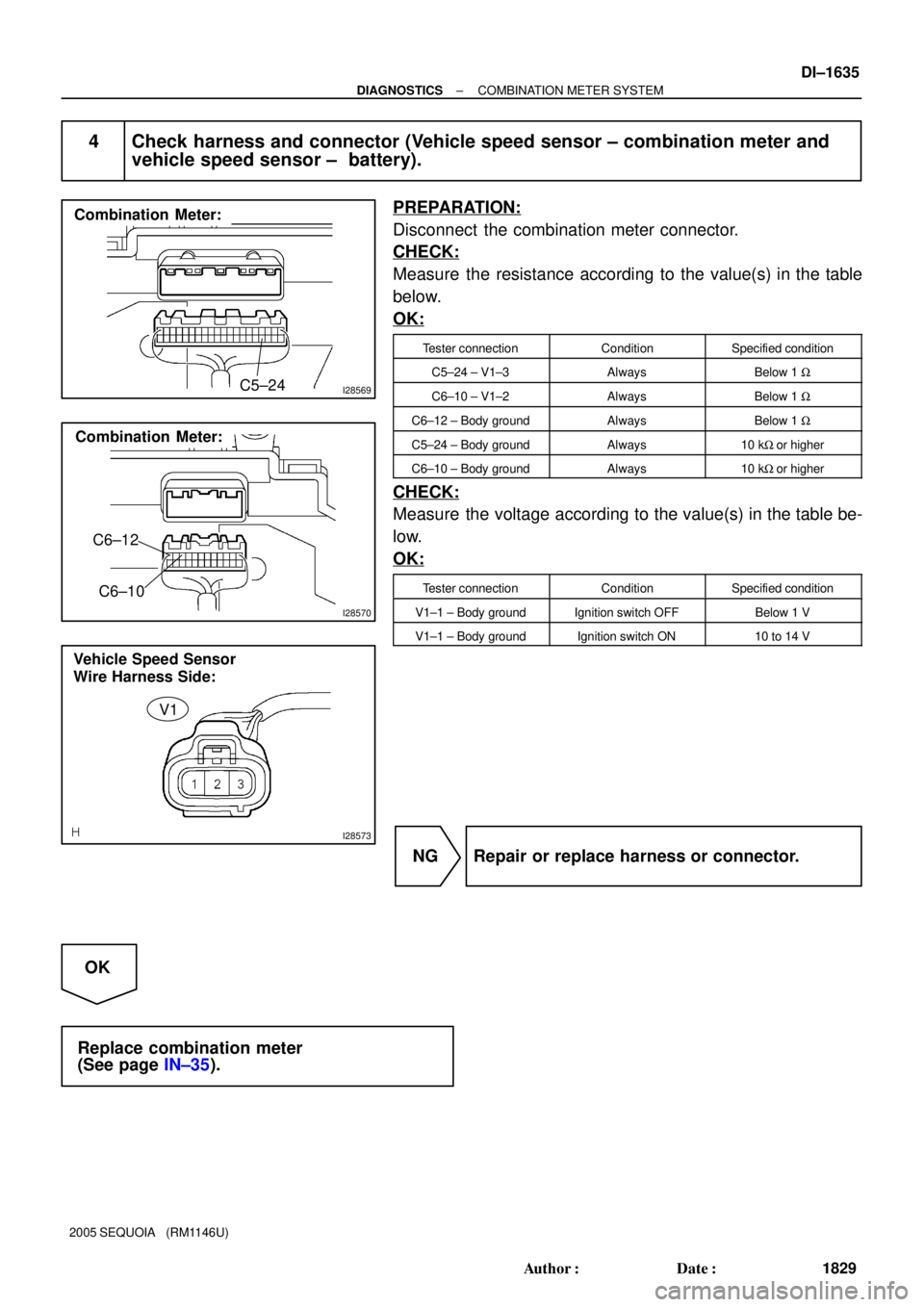
4 Check harness and connector (Vehicle speed sensor ± combination meter and
vehicle speed sensor ± battery).
PREPARATION:
Disconnect the combination meter connector.
CHECK:
Measure the resistance according to the value(s) in the table
below.
OK:
Tester connectionConditionSpecified condition
C5±24 ± V1±3AlwaysBelow 1 W
C6±10 ± V1±2AlwaysBelow 1 W
C6±12 ± Body groundAlwaysBelow 1 W
C5±24 ± Body groundAlways10 kW or higher
C6±10 ± Body groundAlways10 kW or higher
CHECK:
Measure the voltage according to the value(s) in the table be-
low.
OK:
Tester connectionConditionSpecified condition
V1±1 ± Body groundIgnition switch OFFBelow 1 V
V1±1 ± Body groundIgnition switch ON10 to 14 V
NG Repair or replace harness or connector.
OK
Replace combination meter
(See page IN±35).
Page 1838 of 4323
I28559
E5 C5 ECU
TACHCombination Meter
23 J/C
J14D
J15F
Y±G Y±G 1 DI±1636
± DIAGNOSTICSCOMBINATION METER SYSTEM
1830 Author�: Date�:
2005 SEQUOIA (RM1146U)
Malfunction in tachometer
CIRCUIT DESCRIPTION
The indication on the tachometer is based on information that the ECM receives from the crankshaft position
sensor.
WIRING DIAGRAM
DID90±01
Page 1846 of 4323

Malfunction in engine coolant temperature receiver gauge
CIRCUIT DESCRIPTION
The ECM receives an engine co")
DI±1644
± DIAGNOSTICSCOMBINATION METER SYSTEM
1838 Author�: Date�:
2005 SEQUOIA (RM1146U)
Malfunction in engine coolant temperature receiver gauge
CIRCUIT DESCRIPTION
The ECM receives an engine coolant temperature signal from the engine coolant temperature sensor and
sends it to the A/C ECU.
The combination meter receives the signal from the A/C ECU through multiplex communication. Therefore,
if a malfunction occurs in the engine coolant temperature receiver gauge, there may be a malfunction in the
multiplex communication system, air conditioning system, or engine system.
(Multiplex communication system: See page DI±1892)
(Air conditioning system: See page DI±2301)
(Engine system: See page DI±9)
INSPECTION PROCEDURE
1 Perform active test by hand±held tester.
PREPARATION:
(a) Connect the hand±held tester to the DLC3.
(b) Turn the ignition switch ON, and push the hand±held tester main switch ON.
CHECK:
From the display on the tester, perform the ºACTIVE TESTº.
METER:
ItemTest DetailsDiagnostic Note
COOLANT TEMPHIGH / NORMAL / LOW (OFF)Confirm that the vehicle is stopped and engine is
idling.
OK:
Engine coolant temperature receiver gauge readings change according to hand±held tester op-
eration.
OK Go to engine system or air conditioning system
(See page DI±9 or DI±2301).
NG
Replace combination meter
(See page IN±35).
DID92±01
Page 1868 of 4323

DATA LIST / ACTIVE TEST
1. DATA LIST
HINT:
According to the DATA LIST displayed by the hand±held te")
DID4Z±01
DI±1666
± DIAGNOSTICSSLIDING ROOF SYSTEM
1860 Author�: Date�:
2005 SEQUOIA (RM1146U)
DATA LIST / ACTIVE TEST
1. DATA LIST
HINT:
According to the DATA LIST displayed by the hand±held tester, you can read the value of the switch, sensor,
actuator and so on without parts removal. Reading the DATA LIST as a first step of troubleshooting is one
of the method to shorten the labor time.
(a) Connect the hand±held tester to the DLC3.
(b) Turn the ignition switch ON.
(c) According to the display on tester, read the ºDATA LISTº.
SLIDE ROOF:
ItemMeasurement Item/
Display (Range)Normal conditionDiagnostic Note
LIMIT SW 1Position SW NO.1/
ON or OFFON: 250 mm point from fully opened position
OFF: Sliding roof fully closed position±
LIMIT SW 2Position SW NO.2/
ON or OFFON: Sliding roof fully closed position
OFF: Sliding roof except fully closed position±
OPEN SWSliding roof open SW
signal/ON or OFFON: Sliding roof is open
OFF: Sliding roof is close±
CLOSE SWSliding roof close SW
signal/ON or OFFON: Sliding roof is close
OFF: Sliding roof is open±
UP SWSliding roof up SW sig-
nal/ON or OFFON: Sliding roof is up
OFF: Sliding roof is down±
DOWN SWSliding roof down SW
signal/ON or OFFON: Sliding roof is down
OFF: Sliding roof is up±
IG (DIRCT)Ignition SW (Direct
signal)/ON or OFFON: Ignition switch to on
OFF: Ignition switch to off±
IG (MPX)Ignition SW (MPX)/ON
or OFFON: Ignition switch to on
OFF: Ignition switch to off±
2. ACTIVE TEST
HINT:
Performing the ACTIVE TEST using the hand±held tester allows the relay, VSV, actuator and so on to oper-
ate without parts removal. Performing the ACTIVE TEST as a first step of troubleshooting is one of the meth-
od to shorten the labor time.
It is possible to display the DATA LIST during the ACTIVE TEST.
(a) Connect the hand±held tester to the DLC3.
(b) Turn the ignition switch ON.
(c) According to the display on tester, perform the ºACTIVE TESTº.
SLIDE ROOF:
ItemTest DetailsDiagnostic Note
SLIDE ROOFSliding roof CLOS/UP ± OPN/DWNDuring this ACTIVE TEST, jam protection caught
detection can be monitored.
Page 1883 of 4323
I28734
BODY ECU
Back Door
Power Window SW
Rear Wiper
and
Washer
Switch
Rear Washer
Motor
Theft Deterrent Horn
Light
Control
Sensor
Wireless
Door Lock
Receiver ECU±B From
Battery
DLC3From
Battery
POWER MAIN
Power
Window SW
(RR)Power
Window
Motor (RR)PWR
No. 3
PWR
No. 2
Power
Window SW
(RL)Power
Window
Motor (RL)
From
Battery
From
Battery DOME
HORN Interior Light
HORN
Vehicle Horn
Combination Meter
Security Indicator
Horn Switch
Glass
Breakage
Sensor ECUWireless Buzzer
ECU±B
HTR PWS
BUP
BDN
RWLS
RWC1
RWW
SHTRCY
RRU
RRD
RLU
RLD
ILE
CLTB
CLTS
CLTEHR
RDA
PRG
GND1IND
HORN
BZR
OBD2DOP
Microphone
From
Battery
± DIAGNOSTICSBODY CONTROL SYSTEM
DI±1681
1875 Author�: Date�:
2005 SEQUOIA (RM1146U)
Page 1888 of 4323

PROBLEM SYMPTOMS TABLE
DOOR LOCK CONTROL
SymptomSuspected AreaSee page
Lock or unlock cannot be opera")
DI1OH±18
DI±1686
± DIAGNOSTICSBODY CONTROL SYSTEM
1880 Author�: Date�:
2005 SEQUOIA (RM1146U)
PROBLEM SYMPTOMS TABLE
DOOR LOCK CONTROL
SymptomSuspected AreaSee page
Lock or unlock cannot be operated with door lock control switch.
1. Door lock control switch (Power source circuit)
(Driver's)
(Passenger's)
2. Body ECU
DI±1788
DI±1826
IN±35
Door key linked function does not operate.
1. Door key lock and unlock switch circuit (Driver's)
(Passenger's)
2. Body ECUDI±1794
DI±1832
IN±35
Key confinement prevention function does not operate.1. Key unlock warning switch circuit
2. Body ECUDI±1715
IN±35
Door lock function does not operate.1. Door lock motor circuit
2. Body ECUDI±1720
IN±35
THEFT DETERRENT SYSTEM
SymptomSuspected AreaSee page
No alerting condition is operated. (The system cannot be set.)
1. Security indicator circuit
2. Key unlock warning switch circuit
3. Courtesy light switch circuit
4. Door unlock detection switch circuit (Driver's)
(Passenger's)
5. Engine hood courtesy light switch circuit
6. Back door courtesy light switch circuit
7. Back door ECU
8. Body ECUDI±1731
DI±1715
DI±1728
DI±1791
DI±1829
DI±1725
DI±1864
IN±35
IN±35
Cannot be canceled when IG is turned ON with a key.
1. Key unlock warning switch circuit
2. Ignition switch
3. Body ECUDI±1715
BE±24
IN±35
Cannot be canceled when unlocking the back door with a key.1. Back door ECU
2. Body ECUIN±35
IN±35
Headlights do not light up as an alert function.1. Headlight relay circuit
2. Body ECUDI±1708
IN±35
Taillights do not light up as an alert function.1. Taillight relay circuit
2. Body ECUDI±1706
IN±35
Theft deterrent horn or vehicle horn does not sound.
1. Security horn circuit
2. Horn circuit
3. Body ECUDI±1734
DI±1764
IN±35
During warning condition, cannot be canceled by unlocking the
door with a key.1. Door key lock and unlock switch circuit (Driver's)
(Passenger's)
2. Body ECUDI±1794
DI±1832
IN±35
During warning condition, cannot be canceled by unlocking the
door with a key. (transmitter)1. Transmitter
2. Body ECUBE±99
IN±35
During warning condition, cannot be canceled by turning the igni-
tion ON with a key.1. Ignition switch
2. Key unlock warning switch circuit
3. Body ECUBE±24
DI±1715
IN±35
The system operated for more than 60 seconds.Body ECUIN±35
Glass breakage sensor does not operate.1. Glass breakage sensor circuit
2. Body ECUDI±1774
IN±35