Page 1697 of 4323
H23040
LA
A20
± DIAGNOSTICSSUPPLEMENTAL RESTRAINT SYSTEM
DI±1495
1689 Author�: Date�:
2005 SEQUOIA (RM1146U)
5 Check combination meter.
PREPARATION:
(a) Turn the ignition switch to the LOCK position.
(b) Disconnect the negative (±) terminal cable from the bat-
tery, and wait for at least 90 seconds.
(c) Connect the connector to the combination meter.
(d) Connect the negative (±) terminal cable to the battery,
and wait for at least 2 seconds.
CHECK:
(a) Turn the ignition switch to the ON position.
(b) Measure the voltage according to the value(s) in the table
below.
OK:
Tester ConnectionConditionSpecified Condition
A20±14 (LA) ±
Body groundIgnition switch ON8 to 14 V
NG Replace combination meter
(see page BO±89).
OK
Replace airbag sensor assembly (see page RS±82).
Page 1698 of 4323

SRS Warning Light Circuit Malfunction (Does not light up, when
ignition switch is turned to on)
CIRCU")
DI±1496
± DIAGNOSTICSSUPPLEMENTAL RESTRAINT SYSTEM
1690 Author�: Date�:
2005 SEQUOIA (RM1146U)
SRS Warning Light Circuit Malfunction (Does not light up, when
ignition switch is turned to on)
CIRCUIT DESCRIPTION
The SRS warning light is located on the combination meter assembly.
When the SRS is normal, the SRS warning light comes on for approximately 6 seconds after the ignition
switch is turned from the LOCK position to the ON position, and then goes off automatically.
If there is a malfunction in the SRS, the SRS warning light comes on to inform the driver of a problem.
When terminals TC and CG of the DLC3 are connected, the DTC is displayed by blinking the SRS warning
light.
WIRING DIAGRAM
See page DI±1491.
INSPECTION PROCEDURE
CAUTION:
Be sure to perform the following procedures before troubleshooting to avoid unexpected airbag de-
ployment.
(a) Turn the ignition switch to the LOCK position.
(b) Disconnect the negative (±) terminal cable from the battery, and wait for at least 90 seconds.
(c) Disconnect the connectors from the airbag sensor assembly.
(d) Disconnect the connectors from the steering wheel pad.
(e) Disconnect the connectors from the front passenger airbag assembly.
(f) w/ Side and curtain shield airbag:
Disconnect the connectors from the side airbag assembly LH and RH.
(g) w/ Side and curtain shield airbag:
Disconnect the connectors from the curtain shield airbag assembly LH and RH.
(h) Disconnect the connectors from the front seat outer belt LH and RH.
1 Check battery.
CHECK:
Measure the voltage of the battery.
OK:
Voltage: 11 to 14 V
NG Replace battery.
OK
DIDHV±01
Page 1699 of 4323

2 Check combination meter.
PREPARATION:
Connect the negative (±) terminal cable to th")
H23040
LA A20
± DIAGNOSTICSSUPPLEMENTAL RESTRAINT SYSTEM
DI±1497
1691 Author�: Date�:
2005 SEQUOIA (RM1146U)
2 Check combination meter.
PREPARATION:
Connect the negative (±) terminal cable to the battery, and wait for at least 2 seconds.
CHECK:
Turn the ignition switch to the ON position, check the operation of the SRS warning light.
OK:
The SRS warning light comes on (goes off 6 seconds after the ignition switch is turned to the
ON position).
NG Go to step 3.
OK
Replace airbag sensor assembly (see page RS±82).
3 Check wire harness (combination meter ± airbag sensor assembly).
PREPARATION:
(a) Turn the ignition switch to the LOCK position.
(b) Disconnect the negative (±) terminal cable from the bat-
tery, and wait for at least 90 seconds.
(c) Disconnect the connector from the combination meter.
(d) Connect the negative (±) terminal cable to the battery,
and wait for at least 2 seconds.
CHECK:
(a) Turn the ignition switch to the ON position.
(b) Measure the voltage according to the value(s) in the table
below.
OK:
Tester ConnectionConditionSpecified Condition
A20±14 (LA) ±
Body groundIgnition switch ONBelow 1 V
NG Repair or replace wire harness.
OK
Replace combination meter (see page BO±89).
Page 1702 of 4323
H23483CG
DLC3:
D6
H23040TC
A20
DI±1500
± DIAGNOSTICSSUPPLEMENTAL RESTRAINT SYSTEM
1694 Author�: Date�:
2005 SEQUOIA (RM1146U)
2 Check wire harness (CG of DLC3 ± body ground).
CHECK:
Measure the resistance according to the value(s) in the table
below.
OK:
Tester ConnectionConditionSpecified Condition
D6±4 (CG) ± Body groundAlwaysBelow 1 W
NG Repair or replace wire harness (CG of DLC3 to
body ground).
OK
3 Check wire harness (TC of airbag sensor assembly ± body ground).
CHECK:
Measure the resistance according to the value(s) in the table
below.
OK:
Tester ConnectionConditionSpecified Condition
A20±15 (TC) ±
Body groundAlways1 MW or higher
NG Repair or replace wire harness or each ECU.
OK
Replace airbag sensor assembly (see page RS±82).
Page 1703 of 4323
DIDDW±01
± DIAGNOSTICSPOWER SEAT CONTROL SYSTEM (w/ Driving Position
Memory)DI±1501
1695 Author�: Date�:
2005 SEQUOIA (RM1146U)
POWER SEAT CONTROL SYSTEM (w/ Driving Position
Memory)
PRECAUTION
NOTICE:
When disconnecting the battery terminal, initialize the following system after the terminal is recon-
nected.
System NameSee Page
Back Door Power Window Control SystemBE±77
Page 1707 of 4323
DIDE1±01
± DIAGNOSTICSPOWER SEAT CONTROL SYSTEM (w/ Driving Position
Memory)DI±1505
1699 Author�: Date�:
2005 SEQUOIA (RM1146U)
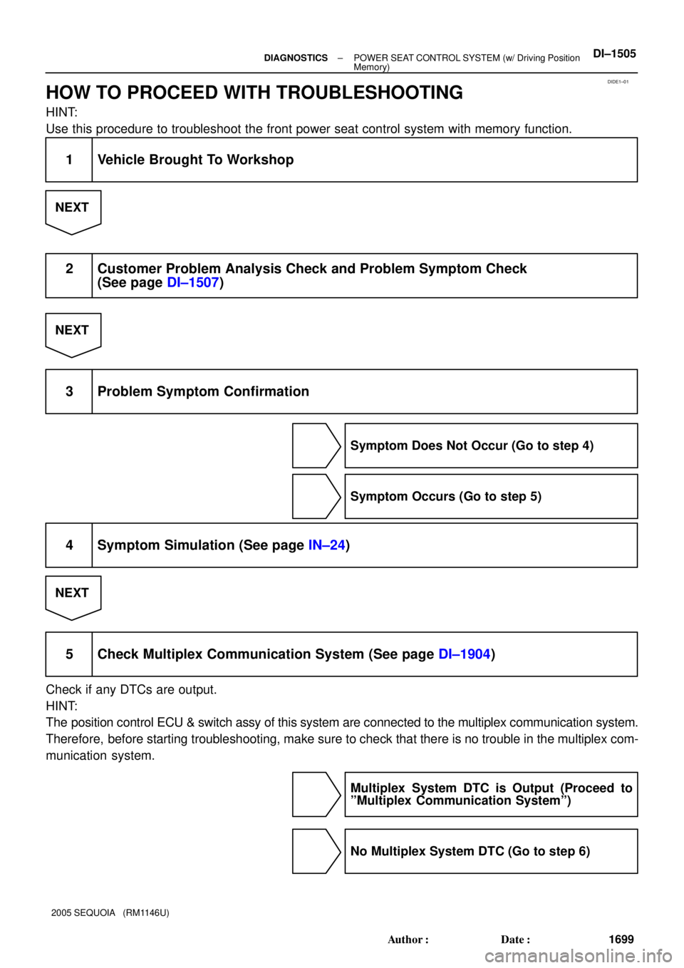
HOW TO PROCEED WITH TROUBLESHOOTING
HINT:
Use this procedure to troubleshoot the front power seat control system with memory function.
1 Vehicle Brought To Workshop
NEXT
2 Customer Problem Analysis Check and Problem Symptom Check
(See page DI±1507)
NEXT
3 Problem Symptom Confirmation
Symptom Does Not Occur (Go to step 4)
Symptom Occurs (Go to step 5)
4 Symptom Simulation (See page IN±24)
NEXT
5 Check Multiplex Communication System (See page DI±1904)
Check if any DTCs are output.
HINT:
The position control ECU & switch assy of this system are connected to the multiplex communication system.
Therefore, before starting troubleshooting, make sure to check that there is no trouble in the multiplex com-
munication system.
Multiplex System DTC is Output (Proceed to
ºMultiplex Communication Systemº)
No Multiplex System DTC (Go to step 6)
Page 1708 of 4323
DI±1506± DIAGNOSTICSPOWER SEAT CONTROL SYSTEM (w/ Driving Position
Memory)
1700 Author�: Date�:
2005 SEQUOIA (RM1146U)
6 Problem Symptoms Table (See page DI±1508)
NEXT
7 Identification of Problem
NEXT
8 Adjustment, Repair or Replace
NEXT
9 Confirmation Test
NEXT
End
Page 1710 of 4323

1702 Author�: Date�:
2005 SEQUOIA (RM1146U)
PROBLEM SYMPTOMS TABLE
HINT:
�If the cause of the problem still ca")
DIDE4±01
DI±1508± DIAGNOSTICSPOWER SEAT CONTROL SYSTEM (w/ Driving Position
Memory)
1702 Author�: Date�:
2005 SEQUOIA (RM1146U)
PROBLEM SYMPTOMS TABLE
HINT:
�If the cause of the problem still cannot be determined after the corresponding inspection, proceed to
the next step shown in this table.
�The system uses multiplex communication. Check for DTCs for the multiplex communication system
before performing the following inspection.
SymptomSuspected AreaSee Page
Power seat does not operate (manual or memorized positions).1. Power source circuit
2. Position control ECU & switch assyDI±1514
BO±112
One function of power seat does not operate (manual or memo-
rized positions).1. Power seat motor circuit
2. Position control ECU & switch assyDI±1525
BO±112
One or all manual seat functions do not operate (memorized
positions OK).Position control ECU & switch assyBO±112
Memory function does not operate.
1. Power source circuit
2. Power seat memory switch circuit
3. Park/neutral position switch circuit
4. Door courtesy switch circuit
5. Position control ECU & switch assyDI±1514
DI±1518
DI±1528
DI±1533
BO±112
All memory functions do not operate or operate a little then stop
(manual functions OK).1. Power source circuit
2. Position control ECU & switch assyDI±1514
BO±112
One memory function does not operate or operates a little then
stops (manual functions OK).1. Power seat motor circuit
2. Position control ECU & switch assyDI±1525
BO±112
Lumbar support does not operate.Lumbar support control switch circuitDI±1521
The power seat control system does not control the storing and
restoring of the power mirror position.
1. Multiplex communication system
2. Driving position memory switch
3. Outer mirror assy
4. Position control ECU & switch assyDI±1904
BE±115
BE±115
BO±112