Page 1762 of 4323
I28461
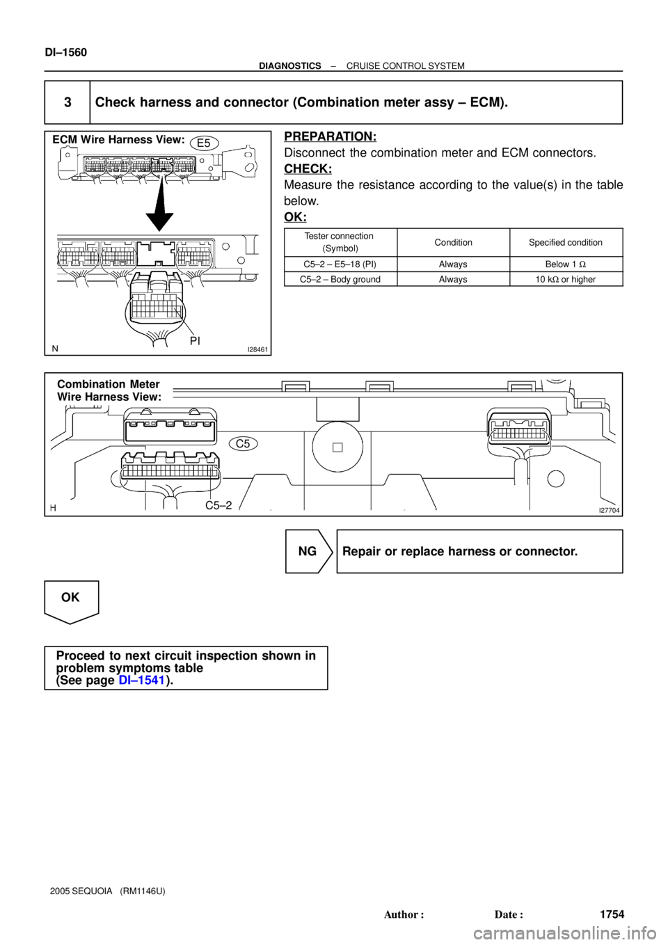
ECM Wire Harness View:
E5
PI
I27704
C5
Combination Meter
Wire Harness View:
C5±2
DI±1560
± DIAGNOSTICSCRUISE CONTROL SYSTEM
1754 Author�: Date�:
2005 SEQUOIA (RM1146U)
3 Check harness and connector (Combination meter assy ± ECM).
PREPARATION:
Disconnect the combination meter and ECM connectors.
CHECK:
Measure the resistance according to the value(s) in the table
below.
OK:
Tester connection
(Symbol)ConditionSpecified condition
C5±2 ± E5±18 (PI)AlwaysBelow 1 W
C5±2 ± Body groundAlways10 kW or higher
NG Repair or replace harness or connector.
OK
Proceed to next circuit inspection shown in
problem symptoms table
(See page DI±1541).
Page 1765 of 4323
I28553
+/RES
CANCEL±/SETON±
OFF
312
± DIAGNOSTICSCRUISE CONTROL SYSTEM
DI±1563
1757 Author�: Date�:
2005 SEQUOIA (RM1146U)
Proceed to next circuit inspection shown in
problem symptoms table
(See page DI±1541).
2 Check cruise control switch continuity.
PREPARATION:
(a) Remove the steering wheel center pad.
(b) Disconnect the cruise control switch connector.
CHECK:
Measure the resistance according to the value(s) in the table
below.
OK:
Switch conditionTester connectionSpecified condition
Neutral1 ± 3Below 1 W
RES/+1 ± 3210 to 270 W
SET/±1 ± 3560 to 700 W
CANCEL1 ± 31,380 to 1,700 W
Main Switch OFF1 ± 310 kW or higher
Main Switch ON1 ± 3Below 1 W
NG Replace cruise control switch.
OK
Page 1768 of 4323
I28461
E5
CCS
ECM Wire Harness View:
I28554
C9
Vehicle Side Connector Front View:
12
3456
78101112 9
DI±1566
± DIAGNOSTICSCRUISE CONTROL SYSTEM
1760 Author�: Date�:
2005 SEQUOIA (RM1146U)
5 Check harness and connector (ECM ± spiral cable sub±assy).
PREPARATION:
Disconnect the ECM connector.
CHECK:
Measure the resistance according to the value(s) in the table
below.
OK:
Tester connection
(Symbol)ConditionSpecification
C9±5 ± E5±2 (CCS)AlwaysBelow 1 W
C9±4 ± Body groundAlways10 kW or higher
C9±5 ± Body groundAlwaysBelow 1 W
NG Repair or replace harness or connector.
OK
Replace ECM (See page IN±35
).
Page 1771 of 4323
C00083CG
D6DLC3:
C00083
TCDLC3:
D6
± DIAGNOSTICSCRUISE CONTROL SYSTEM
DI±1569
1763 Author�: Date�:
2005 SEQUOIA (RM1146U)
2 Check harness and connector (CG of DLC3 ± Body ground).
CHECK:
Measure the resistance according to the value(s) in the table
below.
OK:
Symbol
(Tester connection)ConditionSpecified condition
CG (D6±4) ± Body groundAlwaysBelow 1 W
NG Repair or replace harness or connector.
OK
3 Check harness and connector (TC of DLC3 ± Body ground).
CHECK:
Measure the resistance according to the value(s) in the table
below.
OK:
Symbol
(Tester connection)ConditionSpecified condition
TC (D6±13) ± Body
groundAlways10 kW or higher
NG Repair or replace harness, connector or each
ECU.
OK
Replace ECM (See page IN±35).
Page 1772 of 4323
DID65±01
DI±1570
± DIAGNOSTICSENGINE IMMOBILISER SYSTEM
1764 Author�: Date�:
2005 SEQUOIA (RM1146U)
ENGINE IMMOBILISER SYSTEM
PRECAUTION
NOTICE:
When disconnecting the battery terminal, initialize the following system after the terminal is recon-
nected.
System NameSee Page
Back Door Power Window Control SystemBE±77
Page 1773 of 4323

DI1AJ±49
Vehicle Brought to Workshop
Customer Problem Analysis
Check and Clear DTCItems inside
are titles of pages in this manual,
with the page number in the bottom portion. See
the pages for detailed explanations.
Problem Symptom ConfirmationSymptom Simulation Symptom
does not occur
Symptom
occurs
DTC Check
Circuit Inspection and Part Inspection
DTC ChartProblem Symptoms Table
Identification of Problem
Repair
Confirmation Test
End
1
2
3
4
6
77
8
9
10
P. DI±1572
P. DI±1576
P. IN±24
P. DI±1573 P. DI±1576
P. DI±1578
P. DI±1580 ± DI±1599
Multiplex Communication System Inspection * 5
P. DI±1904
*: Confirm that there is no trouble by DTC check.
Normal system code
Trouble code
± DIAGNOSTICSENGINE IMMOBILISER SYSTEM
DI±1571
1765 Author�: Date�:
2005 SEQUOIA (RM1146U)
HOW TO PROCEED WITH TROUBLESHOOTING
HINT:
The ECU of this system is connected to the multiplex communication system. Therefore, before starting trou-
bleshooting, make sure to check that there is no trouble in the multiplex communication system.
Troubleshoot in accordance with the following procedures:
Page 1775 of 4323

PROBLEM SYMPTOMS TABLE
SymptomSuspected AreaSee page
Immobiliser is not set.
(Engine starts wit")
DI1AP±40
± DIAGNOSTICSENGINE IMMOBILISER SYSTEM
DI±1573
1767 Author�: Date�:
2005 SEQUOIA (RM1146U)
PROBLEM SYMPTOMS TABLE
SymptomSuspected AreaSee page
Immobiliser is not set.
(Engine starts with key codes other than the registered key code.)1. Door courtesy light switch circuit (DTC12)
2. Transponder key ECUDI±1585
IN±35
Engine does not start.
1. Key
2. Key unlock warning switch circuit (DTC11)
3. Transponder key coil
4. Transponder key ECU
5. ECM*1
DI±1582
BE±143
IN±35
IN±35
Security indicator is always ON.
1. Security indicator
2. Security indicator light circuit
3. Transponder key ECU*2
DI±1597
IN±35
Security indicator is always ON.
(Although code has been registered in the automatic registration
mode, indicator is not OFF.)1. Transponder key coil
2. Transponder key ECUBE±143
IN±35
Security indicator is OFF.
(When DTC of immobiliser is output)1. Transponder key coil
2. Transponder key ECUBE±143
IN±35
Security indicator is OFF.
(When DTC of immobiliser is not output)1. Security indicator light circuit
2. Diagnosis circuit
3. Transponder key ECUDI±1597
DI±1599
IN±35
Security indicator is abnormally blinking.Transponder key ECUIN±35
No code is output.
1. Power source circuit
2. Diagnosis circuit
3. Transponder key ECUDI±1595
DI±1599
IN±35
*1 : Check that the key which did not start the engine has been registered, and that it is possible to start with
any other already registered key.
*2 : Finish the automatic registration mode because the mode might still be set.
Page 1778 of 4323

0.5")
DID51±01
A04550
CG
OP3
DLC3 12345678
9
1011
13 1516 12 14
TC
I28427
Security Indicator
Light MIL
BR3904
Normal System Code
0.25 Sec.0.25 Sec.
I02680
Diagnostic Trouble Code (Example Code 12, 99)
0.5 Sec. 0.5 Sec.
1.5 Sec. 2.5 Sec.
One Cycle4.5 Sec.Repeat
DI±1576
± DIAGNOSTICSENGINE IMMOBILISER SYSTEM
1770 Author�: Date�:
2005 SEQUOIA (RM1146U)
DTC CHECK / CLEAR
1. INSPECT DIAGNOSIS
(a) Check the DTC using SST check wire.
(1) Turn the ignition switch ON, but do not start the en-
gine.
(2) When checking DTC 99: Using SST, connect termi-
nals 13 (TC) and 4 (CG) of the DLC3.
(3) When checking codes except DTC 99: Using SST,
connect terminals 8 (OP3) and 4 (CG) of the DLC3.
SST 09843±18040
(4) Read the DTC indicated by the number of times the
security indicator light or the MIL blinks.
HINT:
�If no DTC is output, inspect the diagnosis circuits (OP3
and TC) and the security indicator light circuit (See page
DI±1597, DI±1567, DI±1599).
�If the system is operating normally, the light blinks twice
per second.
�As an example, the blinking patterns of the normal system
code and trouble codes 12 and 99 are shown on the left
and below.