Page 486 of 4323
I18
Ignition
SW
A23552
ECM
STOPSTP
ALT
BatteryE4
16 G±Y
J/C1 S14 Stop Light SW
2
G±W
BR7
Stop
Light
LH
R8
Stop
Light
RH3
5
8W±R
A W
High
Mounted
Stop Light
W±B 1L
1 1F
7
F10
Fusible
Link
BlockInstrument
Panel J/B1
4EG±Y
4B8
Brake Inhibit Relay
G±Y 4
See VSC System 2
W
J19
J/CB
C
IC
CC
C
4
BD1
1
22
1H9 H9(*1)
(*2) (*1)(*2)
BD2
12 J/C
A1
4
G±W IG2
*1: w/o Rear Spoiler
*2: w/ Rear Spoiler AM2
To Towing
Converter Relay
W±BST1±
E4 15
4C 4A1
1
3
L±B Sub J/B No.4
2
IGN1 B±O2
4D2
4A
1E 17
2 1C
1 A
J44J11
J/C J10
J
J33
J34 C
3
IJ
52C
2D 11
AM2
B W±RB±R
6
Instrument
Panel J/B
BP1
4 G±W B±O
G±W
G±W G±WSub J/B No.4
J10
J45
4
BJ J57
J/CA
W±BW±B G±W
High
Mounted
Stop LightG±WJ20
J/C G±W H
Engine Room
J/B DI±284
± DIAGNOSTICSENGINE
478 Author�: Date�:
2005 SEQUOIA (RM1146U)
WIRING DIAGRAM
Page 868 of 4323

DTC P2740 Transmission Fluid Temperature Sensor ºBº
Circuit
DTC P2742 Transmission Fluid Temperature Sensor")
DI±666
± DIAGNOSTICSAUTOMATIC TRANSMISSION
860 Author�: Date�:
2005 SEQUOIA (RM1146U)
DTC P2740 Transmission Fluid Temperature Sensor ºBº
Circuit
DTC P2742 Transmission Fluid Temperature Sensor ºBº
Circuit Low Input
DTC P2743 Transmission Fluid Temperature Sensor ºBº
Circuit High Input
CIRCUIT DESCRIPTION
ATF (Automatic Transmission Fluid) temperature sensor No.2 is on the transmission and just in front of the
oil cooler inlet pipeline.
If ECM detects the abnormally high temperature of ATF by this sensor, it draws driver's attention by illuminat-
ing the warning lamp.
HINT:
�The temperature of ATF easily rises when towing, climbing hills and in traffic, etc.
�If the ATF temperature sensor No.2 becomes short±circuited, the signal that indicates the ATF temper-
ature is 150�C (302�F) or higher is input in ECM.
Vehicle conditions when the sensor is normal and when the sensor is short±circuited are indicated
in the table below.
ATF temperature Sensor No.2
StateDetection ConditionSymptomRecovery Condition
�AT fluid temp. more than 150�C
(302�F).�AT Oil Temp. warning light re-
mains on�AT fluid temp. less than 135�C
(275�F). *2
�AT fluid temp. more than 130�C
(266�F).�Shift point too high.�AT fluid temp. less than 110�C
(230�F).
Sensor is normalWhen the conditions (a) and (b)
are satisfied.
(a) AT fluid temp. more than 130�C
(266�F).
(b) Engine coolant temp. more
than 95�C (203�F).
�Lock±up at 3rd gear. *1�AT fluid temp. less than 110�C
(230�F) *2 and engine coolant
temp. less than 95�C (203�F).
Sensor is short±circuited
�Any conditions.
�AT Oil Temp. warning light re-
mains on
�Shift point too high.
�Symptoms still occur
Sensor is short circuited
�Engine coolant temp. more than
95�C (203�F).�Lock±up at 3rd gear. *1�Symptoms still occur
HINT:
*1: When AT fluid temperature is normal, transmission locks up at 5th gear with the shift lever in D position
and at 4th gear with the shift lever in 4 position.
*2: When AT fluid temperature is in normal range, it decreases to less than 135�C (275�F) within 5 minutes
with the shift lever in P or N position in an idling state.
DIDJN±01
Page 3425 of 4323
± BODY ELECTRICALTROUBLESHOOTING
BE±13
3417 Author�: Date�:
2005 SEQUOIA (RM1146U)
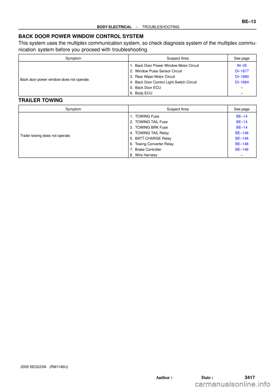
BACK DOOR POWER WINDOW CONTROL SYSTEM
This system uses the multiplex communication system, so check diagnosis system of the multiplex commu-
nication system before you proceed with troubleshooting.
SymptomSuspect AreaSee page
Back door power window does not operate.
1. Back Door Power Window Motor Circuit
2. Window Pulse Sensor Circuit
3. Rear Wiper Motor Circuit
4. Back Door Control Light Switch Circuit
5. Back Door ECU
6. Body ECUIN±35
DI±1877
DI±1880
DI±1864
±
±
TRAILER TOWING
SymptomSuspect AreaSee page
Trailer towing does not operate.
1. TOWING Fuse
2. TOWING TAIL Fuse
3. TOWING BRK Fuse
4. TOWING TAIL Relay
5. BATT CHARGE Relay
6. Towing Converter Relay
7. Brake Controller
8. Wire HarnessBE±14
BE±14
BE±14
BE±148
BE±148
BE±148
BE±148
±
Page 3429 of 4323

I28399
Fusible Link Block:
Relays: Fuses:
5. RR HEATER Fuse 30 A
A. C/OPN Relay
B. HEAD Relay
C. EFI Relay
D. FUEL PUMP Relay
E. DEFOG Relay
F. HORN Relay
Engine Room J/B6. R/B Fuse 30 A
7. A/PUMP Fuse 50 A
8. ABS Fuse 60 A
9. ALT Fuse 140 A
10. CDS FAN Fuse 25 A
11. Spare Fuse 15 A
12. Spare Fuse 20 A
13. Spare Fuse 30 A
14. Main Fuse 40 A
15. DOOR No. 2 Fuse 30 A
16. *2 H±LP RH Fuse 15 A
17. EFI No. 1 Fuse 20 A
18. ETCS Fuse 10 A19. *1.DRL Fuse 15 A
*2.H±LP LH Fuse 15 A
20. ALT±S Fuse 7.5 A
21. TOWING Fuse 30 A
22. ST Fuse 30 A
23. RAD No. 3 Fuse 30 A
24. TURN±HAZ Fuse 20 A
25. AM2 Fuse 25 A
26. EFI No. 2 Fuse 10 A
27. SHORT±PIN
28. HORN Fuse 10 A
29. MIR HTR Fuse 15 A
30. ECU±B Fuse 7.5 A
31. DOME Fuse 10 A
32. RAD No. 1 Fuse 20 A
*1 w/ Daytime Running Light
*2 w/o Daytime Running Light 15
16 17 18
19 20 21
262728
2930
A
B
C
D
EF 1
234
5
6789
10
22 2324 25
31
32
11
12
13141. TOWING R/B Fuse 50 A
2. AIR SUS Fuse 50 A
3. HEATER Fuse 50 A
4. DEFOG Fuse 40 A
± BODY ELECTRICALPOWER SOURCE
BE±17
3421 Author�: Date�:
2005 SEQUOIA (RM1146U)
Page 3430 of 4323
I28550
Engine Room R/B No. 3:
Relays: Fuses:
1. TOWING BRK Fuse 30 A
A. BATT CHARGE Relay
B. TOWING TAIL Relay 2. BATT CHARGE Fuse 30 A
3. TOWING TAIL Fuse 30 A
Driver Side R/B:
Relays:
A. INVERTER Relay
B. SEAT HEATER RelayEngine Room R/B No. 4:
Relays:
A. RR HEATER Relay
B. HEATER Relay BE±18
± BODY ELECTRICALPOWER SOURCE
3422 Author�: Date�:
2005 SEQUOIA (RM1146U)
Page 3559 of 4323
BE26G±04
I28424
Engine Room J/B
� TOWING Fuse
Trailer Socket
Towing Converter Relay
(Located inside of the quarter trim panel LH)
Engine Room R/B No. 3
� BATT CHARGE Relay
� TOWING TAIL Relay
� TOWING BRK Fuse
� TOWING TAIL Fuse
Brake Controller
(Located inside of the cowl side trim board LH)
± BODY ELECTRICALTRAILER TOWING
BE±147
3551 Author�: Date�:
2005 SEQUOIA (RM1146U)
TRAILER TOWING
LOCATION
Page 3560 of 4323

INSPECTION
1. INSPECT TOWING CONVERTER CIRCUIT
Remove the towing converter wi")
BE2D5±02
I24381
Wire Harness Side: BE±148
± BODY ELECTRICALTRAILER TOWING
3552 Author�: Date�:
2005 SEQUOIA (RM1146U)
INSPECTION
1. INSPECT TOWING CONVERTER CIRCUIT
Remove the towing converter with the connector still connected
and inspect the wire harness side connector from the back side,
as shown in the table below.
Tester connectionConditionSpecified condition
4 ± 6Turn signal switch LEFT or hazard warning switch ON10 ± 14 V e 0 V
4 ± 6Turn signal switch LEFT and stop light switch ON (Brake pedal depressed)10 ± 14 V e 0 V
4 ± 6Turn signal switch OFF, hazard warning switch OFF and stop light switch OFF
(Brake pedal released)0 V
4 ± 6Stop light switch ON (Brake pedal depressed)10 ± 14 V
6 ± 9Turn signal switch LEFT or hazard warning switch ON10 ± 14 V e 0 V
6 ± 9Turn signal switch OFF or RIGHT and hazard warning switch OFF0 V
6 ± Body groundAlwaysContinuity
2 ± 6Turn signal switch RIGHT or hazard warning switch ON10 ± 14 V e 0 V
2 ± 6Turn signal switch RIGHT and stop light switch ON (Brake pedal depressed)10 ± 14 V e 0 V
26Turn signal switch OFF, and hazard warning switch OFF and stop light switch OFF0V2 ± 6Turn signal switch OFF, and hazard warning switch OFF and sto light switch OFF
(Brake pedal released)0 V
2 ± 6Stop light switch ON (Brake pedal depressed)10 ± 14 V e 0 V
1 ± 6Always10 ± 14 V
6 ± 8Stop light switch ON (Brake pedal depressed)10 ± 14 V
6 ± 8Stop light switch OFF (Brake pedal released)0 V
3 ± 6Turn signal switch RIGHT or hazard warning switch ON10 ± 14 V e 0 V
3 ± 6Turn signal switch OFF or LEFT and hazard warning switch OFF0 V
If the circuit is not as specified, inspect the circuit connected to
other parts.
Page 3561 of 4323

2. Trailer Socket 7 Pin Type:
INSPECT BRAKE CONTROLLER")
I24379
Wire Harness Side:
I18635
1
2 34
5
I18635
1
2 34
5
± BODY ELECTRICALTRAILER TOWING
BE±149
3553 Author�: Date�:
2005 SEQUOIA (RM1146U)
2. Trailer Socket 7 Pin Type:
INSPECT BRAKE CONTROLLER CIRCUIT
Remove the brake controller with the connector still connected
and inspect the wire harness side connector from the back side,
as shown in the table below.
Tester connectionConditionSpecified condition
1 ± 3Stop light switch ON (Brake pedal depressed)10 ± 14 V
1 ± 3Stop light switch OFF (Brake pedal released)0 V
2 ± 3Always10 ± 14 V
3 ± 4Stop light switch ON (Brake pedal depressed)10 ± 14 V
3 ± 4Stop light switch OFF (Brake pedal released)0 V
3 ± 5Light control switch TAIL or HEAD10 ± 14 V
3 ± 5Light control switch OFF0 V
If the circuit is not as specified, inspect the circuit connected to
other parts.
3. INSPECT TOWING TAIL RELAY CONTINUITY
ConditionTester connectionSpecified condition
Always1 ± 2Continuity
Always3 ± 5No continuity
Apply B+ between
terminals 1 and 2.3 ± 5Continuity
If continuity is not as specified, replace the relay.
4. INSPECT BATT CHARGE RELAY CIRCUIT
ConditionTester connectionSpecified condition
Always1 ± 2Continuity
Always3 ± 5No continuity
Apply B+ between
terminals 1 and 2.3 ± 5Continuity
If continuity is not as specified, replace the relay.