Page 1902 of 1943
AB0158
SSTBattery
H15464
SST
SST
H15465
BO±96
± BODYSEAT BELT PRETENSIONER
2001 PRIUS (RM778U)
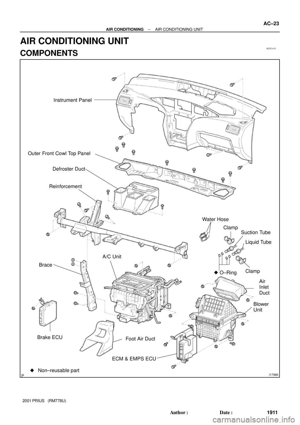
�Be sure to follow the procedure given on the next
page when activating the seat belt pretensioner.
HINT:
Have a battery ready as the power source when activating the
seat belt pretensioner.
(a) Remove the front seat outer belt (See page BO±90).
HINT:
Cut the belt near the seat belt retractor.
(b) Check the functioning of SST.
(See step 1±(a))
SST
Driver's side: 09082±00700, 09082±00730
Except driver's side: 09082±00700, 09082±00740
(c) Install the SST.
(1) Connect the 2 SST, then connect them to the seat
belt pretensioner.
SST
Driver's side: 09082±00700, 09082±00730
Except driver's side: 09082±00700, 09082±00740
NOTICE:
To avoid damaging the SST connector and wire harness.
(2) Place the front seat outer belt on the ground and
cover it with the disc wheel with tire.
NOTICE:
Place the front seat outer belt as shown in the illustration.
Also, secure some slack for the SST wire harness inside
the tire.
(3) Move the SST at least 10 m (33 ft) away from the
disc wheel.
NOTICE:
Take care not to damage the SST wire harness.
(d) Activate the seat belt pretensioner.
(1) Connect the SST red clip to the battery positive (+)
terminal and black clip to the battery negative (±)
terminal.
(2) Check that no one is within 10 m (33 ft) area around
the disc wheel.
(3) Press the SST activation switch and activate the
seat belt pretensioner.
Page 1914 of 1943
N14519
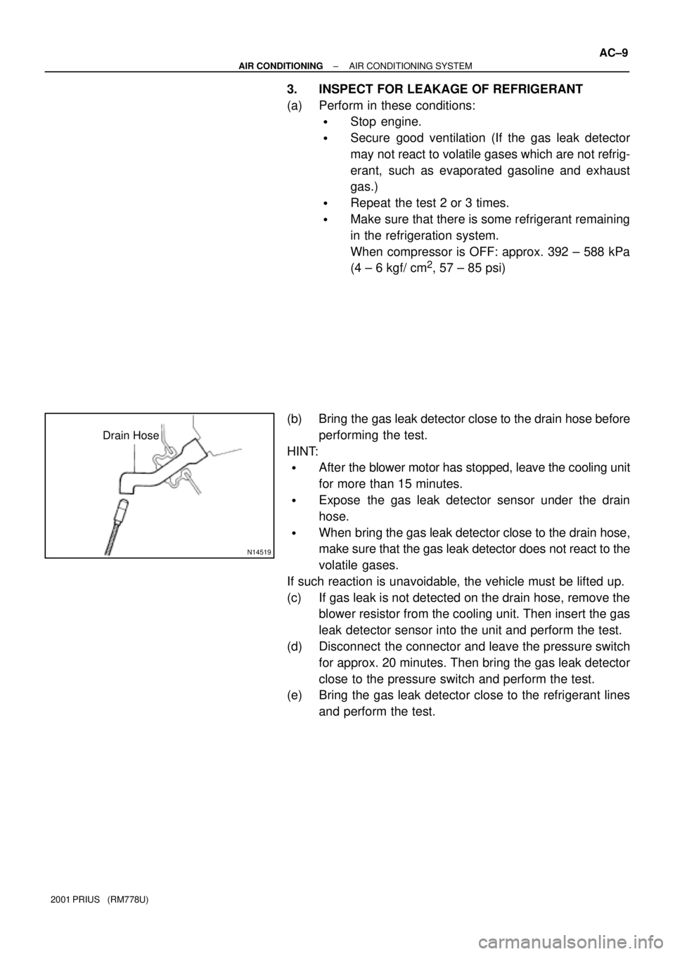
Drain Hose
± AIR CONDITIONINGAIR CONDITIONING SYSTEM
AC±9
2001 PRIUS (RM778U)
3. INSPECT FOR LEAKAGE OF REFRIGERANT
(a) Perform in these conditions:
�Stop engine.
�Secure good ventilation (If the gas leak detector
may not react to volatile gases which are not refrig-
erant, such as evaporated gasoline and exhaust
gas.)
�Repeat the test 2 or 3 times.
�Make sure that there is some refrigerant remaining
in the refrigeration system.
When compressor is OFF: approx. 392 ± 588 kPa
(4 ± 6 kgf/ cm
2, 57 ± 85 psi)
(b) Bring the gas leak detector close to the drain hose before
performing the test.
HINT:
�After the blower motor has stopped, leave the cooling unit
for more than 15 minutes.
�Expose the gas leak detector sensor under the drain
hose.
�When bring the gas leak detector close to the drain hose,
make sure that the gas leak detector does not react to the
volatile gases.
If such reaction is unavoidable, the vehicle must be lifted up.
(c) If gas leak is not detected on the drain hose, remove the
blower resistor from the cooling unit. Then insert the gas
leak detector sensor into the unit and perform the test.
(d) Disconnect the connector and leave the pressure switch
for approx. 20 minutes. Then bring the gas leak detector
close to the pressure switch and perform the test.
(e) Bring the gas leak detector close to the refrigerant lines
and perform the test.
Page 1915 of 1943
AC±10
± AIR CONDITIONINGAIR CONDITIONING SYSTEM
2001 PRIUS (RM778U)
4. INSPECT IDLE±UP SPEED
(a) Activate inspection mode (See page IN±10).
(b) Inspect idle±up speed when the these conditions are es-
tablished.
Test conditions:
�Idle speed set correctly.
�Steering wheel straight ahead
�Blower speed control dial at HI
�A/C switch ON
Magnetic clutch conditionIdle speed
Magnetic clutch not engaged1,000 ±50 rpm
Magnetic clutch engaged1,000 ±50 rpm
If idle speed is not as specified, check the engine ECU and
throttle body.
Page 1918 of 1943
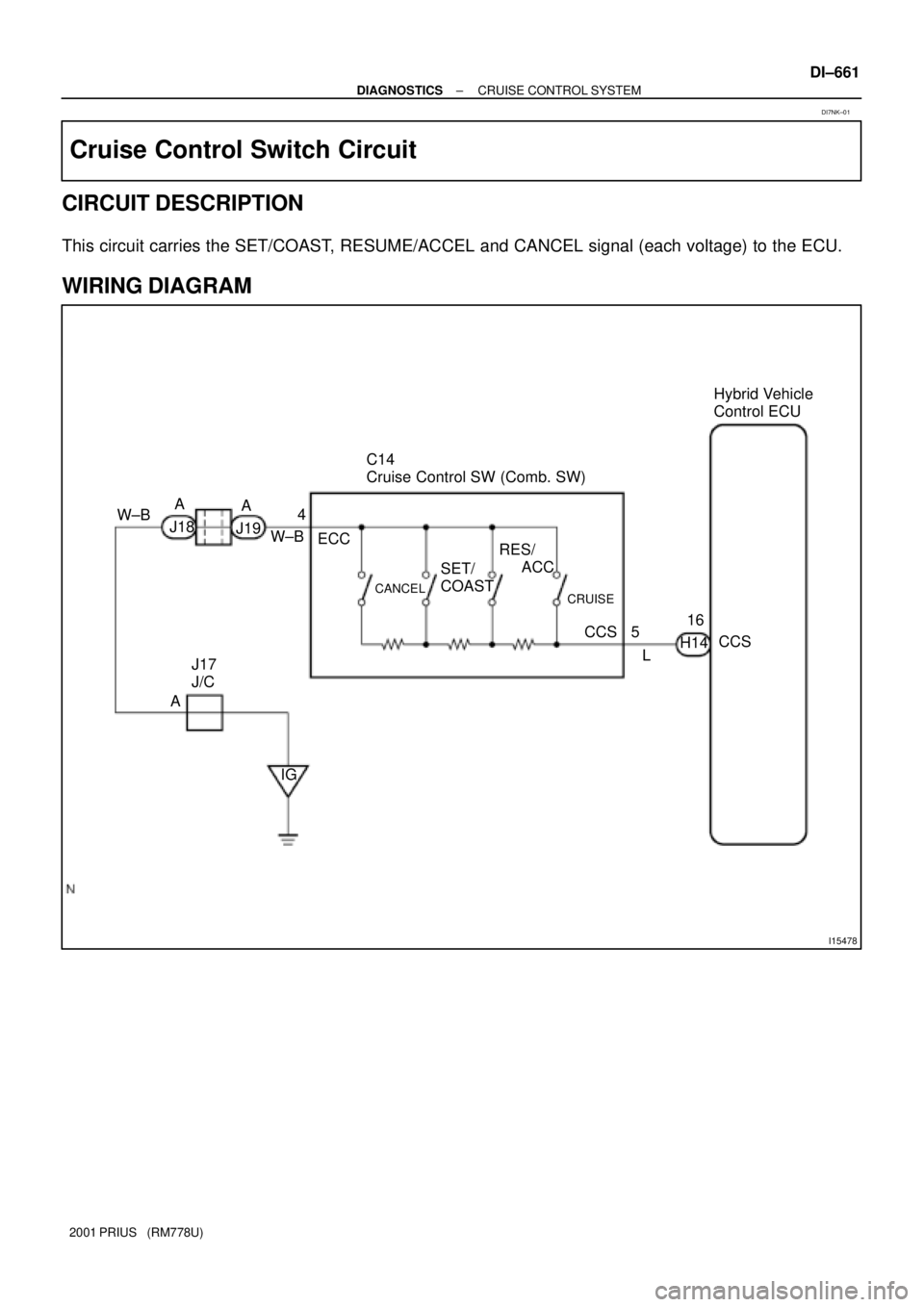
AC37J±01
I17980
Instrument Panel
Outer Front Cowl Top Panel
Defroster Duct
Reinforcement
Brace
Brake ECU
ECM & EMPS ECUFoot Air DuctBlower
UnitAir
Inlet
Duct Clamp Liquid Tube Suction Tube Clamp Water Hose
A/C Unit
�O±Ring
�Non±reusable part
± AIR CONDITIONINGAIR CONDITIONING UNIT
AC±23
1911 Author�: Date�:
2001 PRIUS (RM778U)
AIR CONDITIONING UNIT
COMPONENTS
Page 1938 of 1943
I15478
Hybrid Vehicle
Control ECU
C14
Cruise Control SW (Comb. SW)
A
W±B
5
LCCS 16
H14
CRUISE
CCS RES/
ACC
SET/
COAST
CANCEL
ECC
J17
J/C
IG A W±B
J18A
J194
± DIAGNOSTICSCRUISE CONTROL SYSTEM
DI±661
2001 PRIUS (RM778U)
Cruise Control Switch Circuit
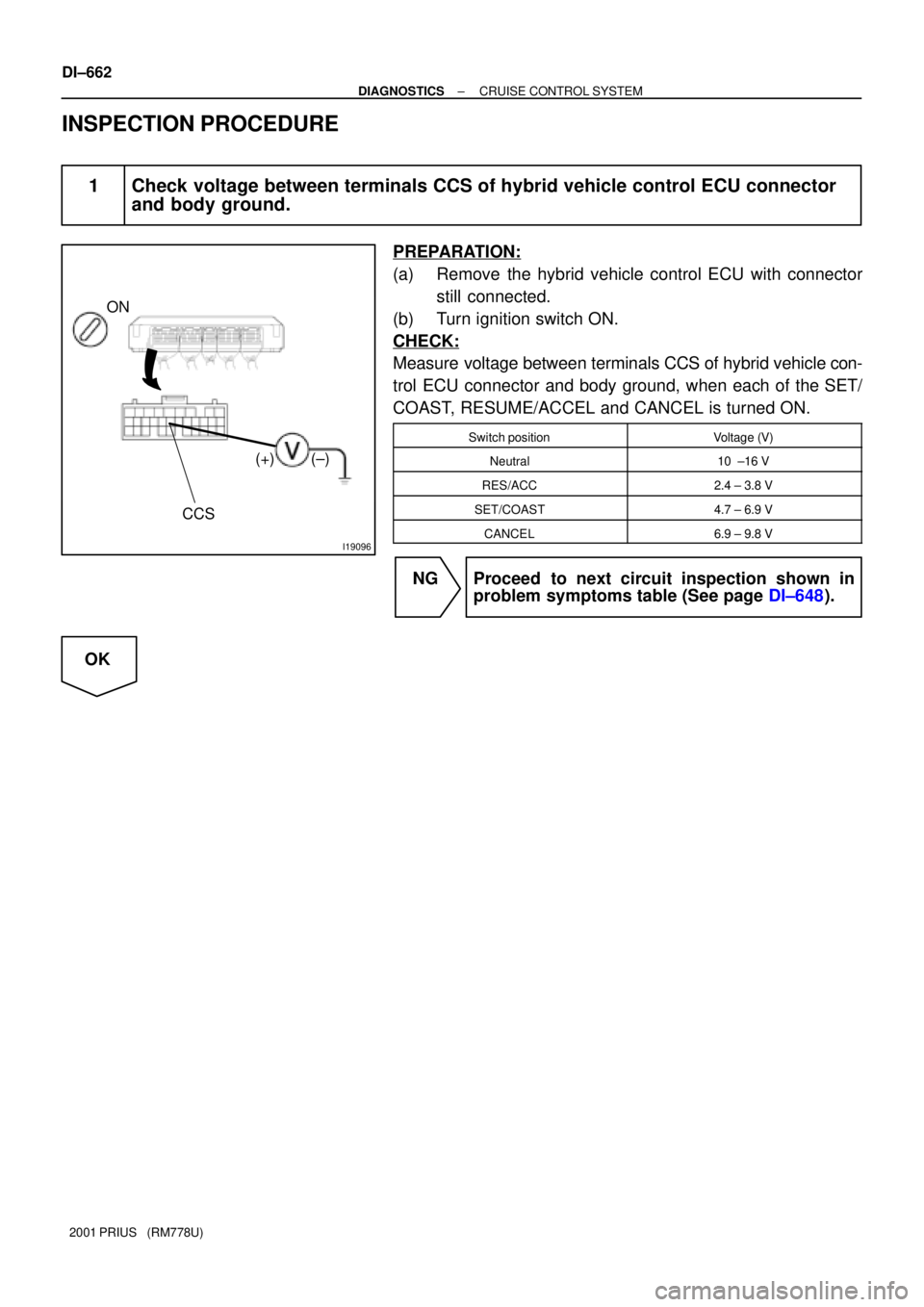
CIRCUIT DESCRIPTION
This circuit carries the SET/COAST, RESUME/ACCEL and CANCEL signal (each voltage) to the ECU.
WIRING DIAGRAM
DI7NK±01
Page 1939 of 1943
I19096
ON
CCS
(+) (±)
DI±662
± DIAGNOSTICSCRUISE CONTROL SYSTEM
2001 PRIUS (RM778U)
INSPECTION PROCEDURE
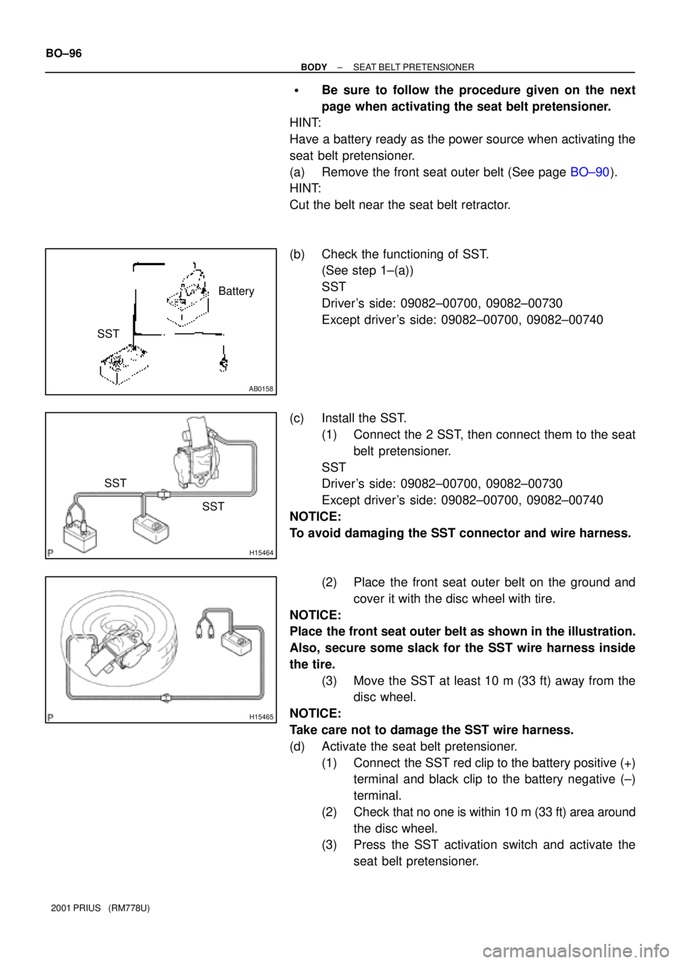
1 Check voltage between terminals CCS of hybrid vehicle control ECU connector
and body ground.
PREPARATION:
(a) Remove the hybrid vehicle control ECU with connector
still connected.
(b) Turn ignition switch ON.
CHECK:
Measure voltage between terminals CCS of hybrid vehicle con-
trol ECU connector and body ground, when each of the SET/
COAST, RESUME/ACCEL and CANCEL is turned ON.
Switch positionVoltage (V)
Neutral10 ±16 V
RES/ACC2.4 ± 3.8 V
SET/COAST4.7 ± 6.9 V
CANCEL6.9 ± 9.8 V
NG Proceed to next circuit inspection shown in
problem symptoms table (See page DI±648).
OK
Page 1941 of 1943
DI±664
± DIAGNOSTICSCRUISE CONTROL SYSTEM
2001 PRIUS (RM778U)
OK
4 Check harness and connector between hybrid vehicle control ECU and cruise
control switch, cruise control switch and body ground
(See page IN±41).
NG Repair or replace harness or connector.
OK
Check and replace hybrid vehicle control
ECU (See page
IN±41).
Page 1943 of 1943
I17867
Fuel Sender Gauge Connector
DI±680
± DIAGNOSTICSCOMBINATION METER SYSTEM
2001 PRIUS (RM778U)
5 Check the body ECU.
CHECK:
With the fuel sender gauge connector connected, check if the
voltage between each of terminal 1 (FV), 5 (FR) and 6 (FE) of
the vehicle side wire harness and connector and the body
ground is normal or not.
ConditionTerminalSpecified value
Ignition switch ON1 (FV) ± Body ground4.5 ± 5.5 V
Ignition switch ON5 (FR) ± Body ground0.5 ± 5.5 V
constant6 (FE) ± Body groundContinuity is always iden-
tified.
No Body ECU faulty.
Ye s
Combination meter ECU faulty.