Page 1842 of 1943
Start
Insert a master key into the key cylinder.
Repeatedly turn the key from ignition switch LOCK to ON 6 times.
Remove the master key. Repeat driver's door open/close operation 7 times.
End
*1: The 1 st door's open/close operation should be done within 15 sec after key insertion.
*2: Remove the key within 20 sec. after the 1 st door's open/close operation.
*1
*2
Within 15 secs.
Within 20 secs.
± BODY ELECTRICALHYBRID VEHICLE IMMOBILISER SYSTEM
BE±109
1776 Author�: Date�:
2001 PRIUS (RM778U)
9. ERASURE OF TRANSPONDER KEY CODE
(a) Do this operation to erase transponder key registration from the transponder key ECU.
HINT:
Delete all other master and sub±key codes leaving the master key code to use the operation. When using
the key which was used before deletion, it is necessary to register the code again.
(b) Initial condition: All doors closed, not key in cylinder.
Page 1843 of 1943
BE1WC±01
I17846
Check Connector
OP1
I01826
Example
ON
OFF
Code 11 Code 21
4.5 sec. 2.5 sec. 1.5 sec.
0.5
sec.
± BODY ELECTRICALHYBRID VEHICLE IMMOBILISER SYSTEM
BE±111
2001 PRIUS (RM778U)
PRE±CHECK
1. TRANSPONDER KEY ECU INPUT CONDITION DIS-
PLAY READ CODE
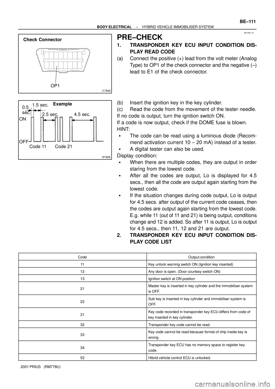
(a) Connect the positive (+) lead from the volt meter (Analog
Type) to OP1 of the check connector and the negative (±)
lead to E1 of the check connector.
(b) Insert the ignition key in the key cylinder.
(c) Read the code from the movement of the tester needle.
If no code is output, turn the ignition switch ON.
If a code is now output, check if the DOME fuse is blown.
HINT:
�The code can be read using a luminous diode (Recom-
mend activation current 10 ± 20 mA) instead of a tester.
�A digital tester can also be used.
Display condition:
�When there are multiple codes, they are output in order
staring from the lowest code.
�After all the codes are output, Lo is displayed for 4.5
secs., then all the code are output again starting from the
lowest code.
�If the situation changes during code output, Lo is output
for 4.5 secs. after output of the current code ceases, then
the codes are output again starting from the lowest code.
E.g. while 11 (out of 11 and 21) is being output, conditions
change and 12 is added. So after 11 is output, Lo is output
for 4.5 secs., then 11, 12 and 21 are output.
2. TRANSPONDER KEY ECU INPUT CONDITION DIS-
PLAY CODE LIST
CodeOutput condition
11Key unlock warning switch ON (Ignition key inserted)
12Any door is open. (Door courtesy switch ON)
13Ignition switch at ON position
21Master key is inserted in key cylinder and the immobiliser system
is OFF.
22Sub key is inserted in key cylinder and immobiliser system is
OFF.
31Key code recorded in transponder key ECU differs from code of
key inserted in key cylinder.
32Transponder key code cannot be read.
33Key code cannot be read because format of chip inside key is
wrong.
34Transponder key ECU has no memory space to register key
code.
52Hibrid vehicle control ECU is unlocked.
Page 1844 of 1943

BE±112
± BODY ELECTRICALHYBRID VEHICLE IMMOBILISER SYSTEM
2001 PRIUS (RM778U)53
Hibrid vehicle control ECU code is error.
54Hibrid vehicle control ECU is check±sum error.
55Hibrid vehicle control ECU is factory code initialling.
58No response from hibrid vehicle control ECU
3. TRANSPONDER KEY ECU INPUT CONDITION DIS-
PLAY MALFUNCTION LIST
SymptomCause
No code is output.
1. DOME Fuse
2. Wire harness or connector
3. Transponder key ECU
Even when key is inserted in key cylinder, Code 11 is not output.
1. Key unlock warning switch
2. Wire harness or connector
3. Transponder key ECU
Code 12 is not output when the door is open.
1. Door courtesy switch
2. Wire harness or connector
3. Transponder key ECU
Code 13 is not output when ignition switch ON.
1. IGN Fuse
2. Wire harness or connector
3. Transponder key ECU
Code 31 is not output when key is inserted in key cylinder.Key code is not registered.
Code 32 is output.
1. Transponder key coil
2. Transponder key ECU
3. Wire harness or connector
Code 33 is output.Transponder key ECU
Code 34 is output.Transponder key ECU has no memory space to register key
code.
Code 51±58 is output.1. Hibrid vehicle control ECU
2. Transponder key ECU
Page 1845 of 1943
The engine dose not starting?
Is DTC code 21, 22 output?
� Wire harness faulty (Open circuit)
� Transponder key EUC faulty
NoYe s
Is DTC code 31, 32, 33
output?
No
� Check the wire harness and connector between the
hybrid vehicle control ECU and transponder key ECU.
� Check that wire harness and connector between the
engine ECU and transponder key ECU.
DTC 31 Go to (a)
DTC 32 Go to (b)
DTC33 Go to (C)
Register the transponder key again.If it cannot be registered (due to chip failure), replace the key.
Hybrid vehicle immobiliser system is normal.
NG
OK
± BODY ELECTRICALHYBRID VEHICLE IMMOBILISER SYSTEM
BE±113
2001 PRIUS (RM778U)
4. TROUBLE SHOOTING
�If code 31 is output, troubleshoot according to this flow chart.
Page 1846 of 1943
Can the engine be started with any other key of the vehicle?
YESNO
Does continuity exist in the coil in continuity test?
Replace the AMP and check if it starts?
Does continuity exist in W/H in continuity test?Replace the coil (Coil broken)Replace the key (Chip failure)
Replace the AMP (AMP failure)
Replace the Transponder key ECU
(Transponder key ECU failure)
Repair or replace the wire harness or the connector.
YES NO YES
NO
YES
NO
Can the engine be started with any other key of the vehicle?
Replace the AMP and check if it starts?
Replace the key (Chip failure)
Replace the Transponder key ECU
(Transponder key ECU failure)YES
NO
Replace the AMP (AMP failure)YES
NO BE±114
± BODY ELECTRICALHYBRID VEHICLE IMMOBILISER SYSTEM
2001 PRIUS (RM778U)
�If code 32 is output, troubleshoot according to this flow chart.
�If code 33 is output, troubleshoot according to this flow chart.
Page 1873 of 1943
H15405
w/o Rain garter:
Windshield Glass
Body
w/ Rain garter:Windshield Moulding
Windshield Moulding
Windshield Glass
Body
H15399Point Marks
BO±50
± BODYWINDSHIELD
2001 PRIUS (RM778U)
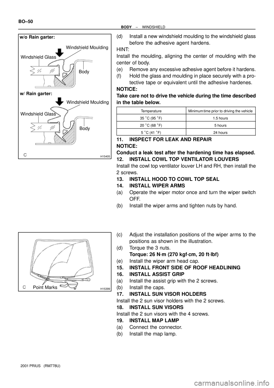
(d) Install a new windshield moulding to the windshield glass
before the adhesive agent hardens.
HINT:
Install the moulding, aligning the center of moulding with the
center of body.
(e) Remove any excessive adhesive agent before it hardens.
(f) Hold the glass and moulding in place securely with a pro-
tective tape or equivalent until the adhesive hardenes.
NOTICE:
Take care not to drive the vehicle during the time described
in the table below.
TemperatureMinimum time prior to driving the vehicle
35 °C (95 °F)1.5 hours
20 °C (68 °F)5 hours
5 °C (41 °F)24 hours
11. INSPECT FOR LEAK AND REPAIR
NOTICE:
Conduct a leak test after the hardening time has elapsed.
12. INSTALL COWL TOP VENTILATOR LOUVERS
Install the cowl top ventilator louver LH and RH, then install the
2 screws.
13. INSTALL HOOD TO COWL TOP SEAL
14. INSTALL WIPER ARMS
(a) Operate the wiper motor once and turn the wiper switch
OFF.
(b) Install the wiper arms and tighten nuts by hand.
(c) Adjust the installation positions of the wiper arms to the
positions as shown in the illustration.
(d) Torque the 3 nuts.
Torque: 26 N´m (270 kgf´cm, 20 ft´lbf)
(e) Install the wiper arm head cap.
15. INSTALL FRONT SIDE OF ROOF HEADLINING
16. INSTALL ASSIST GRIP
(a) Install the assist grip with the 2 screws.
(b) Install the caps.
17. INSTALL SUN VISOR HOLDERS
Install the 2 sun visor holders with the 2 screws.
18. INSTALL SUN VISORS
Install the 2 sun visors with the 4 screws.
19. INSTALL MAP LAMP
(a) Connect the connector.
(b) Install the map lamp.
Page 1879 of 1943
H15386
a
a
b
b
b
b
a ± a b ± b
AA
BB
Adhesive
H10505Reference Marks
H15387
± BODYBACK WINDOW GLASS
BO±57
2001 PRIUS (RM778U)
9. APPLY ADHESIVE
(a) Cut off the tip of the cartridge nozzle.
Part No. 08850±00801 or equivalent
HINT:
After cutting off the tip, use all adhesive within the time de-
scribed in the table below.
TemperatureTackfree time
35°C (95°F)15 minutes
20°C (68°F)100 minutes
5°C (41°F)8 hours
(b) Load the cartridge into the sealer gun.
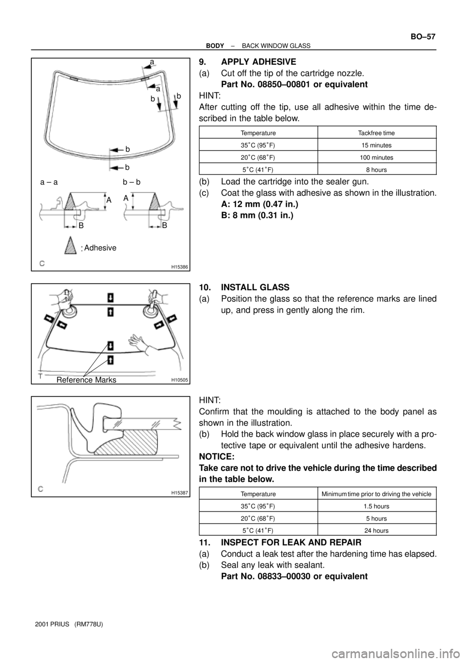
(c) Coat the glass with adhesive as shown in the illustration.
A: 12 mm (0.47 in.)
B: 8 mm (0.31 in.)
10. INSTALL GLASS
(a) Position the glass so that the reference marks are lined
up, and press in gently along the rim.
HINT:
Confirm that the moulding is attached to the body panel as
shown in the illustration.
(b) Hold the back window glass in place securely with a pro-
tective tape or equivalent until the adhesive hardens.
NOTICE:
Take care not to drive the vehicle during the time described
in the table below.
TemperatureMinimum time prior to driving the vehicle
35°C (95°F)1.5 hours
20°C (68°F)5 hours
5°C (41°F)24 hours
11. INSPECT FOR LEAK AND REPAIR
(a) Conduct a leak test after the hardening time has elapsed.
(b) Seal any leak with sealant.
Part No. 08833±00030 or equivalent
Page 1893 of 1943
BO3SW±01
H15371
H15370
Hog Ring
Hog Ring
Hog Ring
H15369
Hog Ring
H15413
± BODYFRONT SEAT
BO±79
2001 PRIUS (RM778U)
REASSEMBLY
NOTICE:
If the seatback frame with the side airbag assembly has
been dropped, or there are cracks, dents or other defects
in the case or connector of the side airbag assembly, re-
place the seatback frame with a new one.
1. INSTALL SET TRACK HANDLE
2. INSTALL RECLINING ADJUSTER INSIDE COVERS
Install the 2 screws and 2 reclining adjuster inside covers.
3. INSTALL SEAT CUSHION COVER
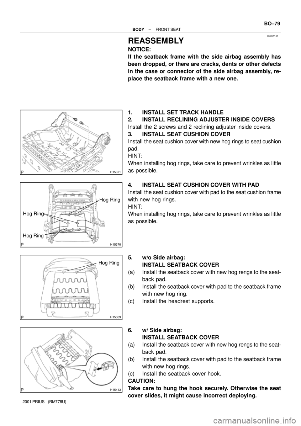
Install the seat cushion cover with new hog rings to seat cushion
pad.
HINT:
When installing hog rings, take care to prevent wrinkles as little
as possible.
4. INSTALL SEAT CUSHION COVER WITH PAD
Install the seat cushion cover with pad to the seat cushion frame
with new hog rings.
HINT:
When installing hog rings, take care to prevent wrinkles as little
as possible.
5. w/o Side airbag:
INSTALL SEATBACK COVER
(a) Install the seatback cover with new hog rengs to the seat-
back pad.
(b) Install the seatback cover with pad to the seatback frame
with new hog ring.
(c) Install the headrest supports.
6. w/ Side airbag:
INSTALL SEATBACK COVER
(a) Install the seatback cover with new hog rengs to the seat-
back pad.
(b) Install the seatback cover with pad to the seatback frame
with new hog rings.
(c) Install the seatback cover hook.
CAUTION:
Take care to hung the hook securely. Otherwise the seat
cover slides, it might cause incorrect deploying.