Page 1744 of 1943

H15519
H15510
SST
R13455
10 m (33 ft) or more
SSTBattery
H03286
± SUPPLEMENTAL RESTRAINT SYSTEMFRONT PASSENGER AIRBAG ASSEMBLY
RS±31
2001 PRIUS (RM778U)
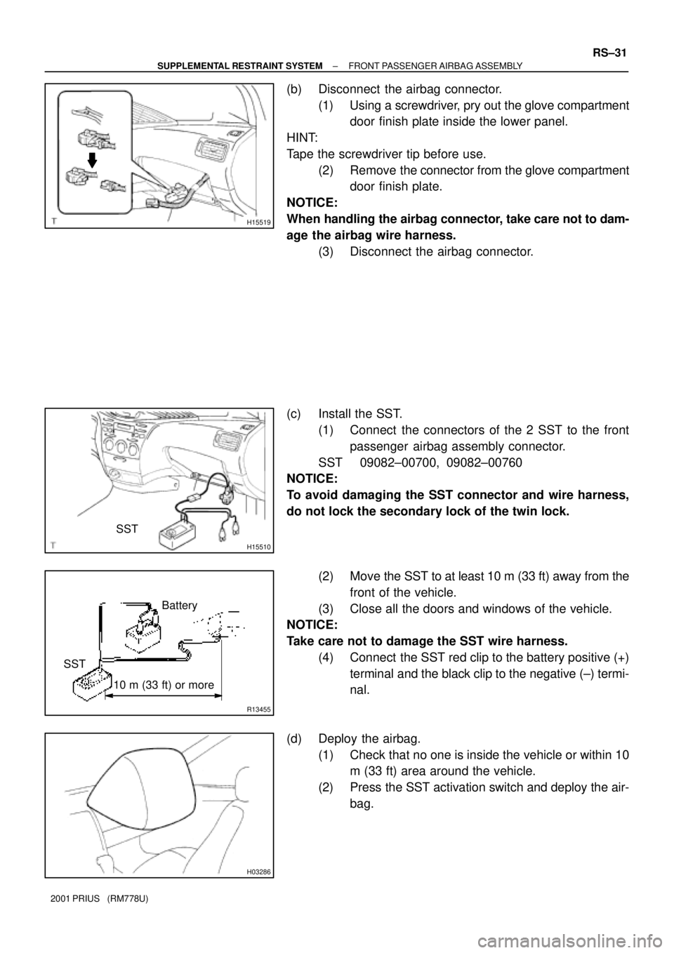
(b) Disconnect the airbag connector.
(1) Using a screwdriver, pry out the glove compartment
door finish plate inside the lower panel.
HINT:
Tape the screwdriver tip before use.
(2) Remove the connector from the glove compartment
door finish plate.
NOTICE:
When handling the airbag connector, take care not to dam-
age the airbag wire harness.
(3) Disconnect the airbag connector.
(c) Install the SST.
(1) Connect the connectors of the 2 SST to the front
passenger airbag assembly connector.
SST 09082±00700, 09082±00760
NOTICE:
To avoid damaging the SST connector and wire harness,
do not lock the secondary lock of the twin lock.
(2) Move the SST to at least 10 m (33 ft) away from the
front of the vehicle.
(3) Close all the doors and windows of the vehicle.
NOTICE:
Take care not to damage the SST wire harness.
(4) Connect the SST red clip to the battery positive (+)
terminal and the black clip to the negative (±) termi-
nal.
(d) Deploy the airbag.
(1) Check that no one is inside the vehicle or within 10
m (33 ft) area around the vehicle.
(2) Press the SST activation switch and deploy the air-
bag.
Page 1751 of 1943

H15678
H15679Battery
SST
R13455
10 m (33 ft) or more
SSTBattery
H15680
± SUPPLEMENTAL RESTRAINT SYSTEMSIDE AIRBAG ASSEMBLY
RS±43
2001 PRIUS (RM778U)
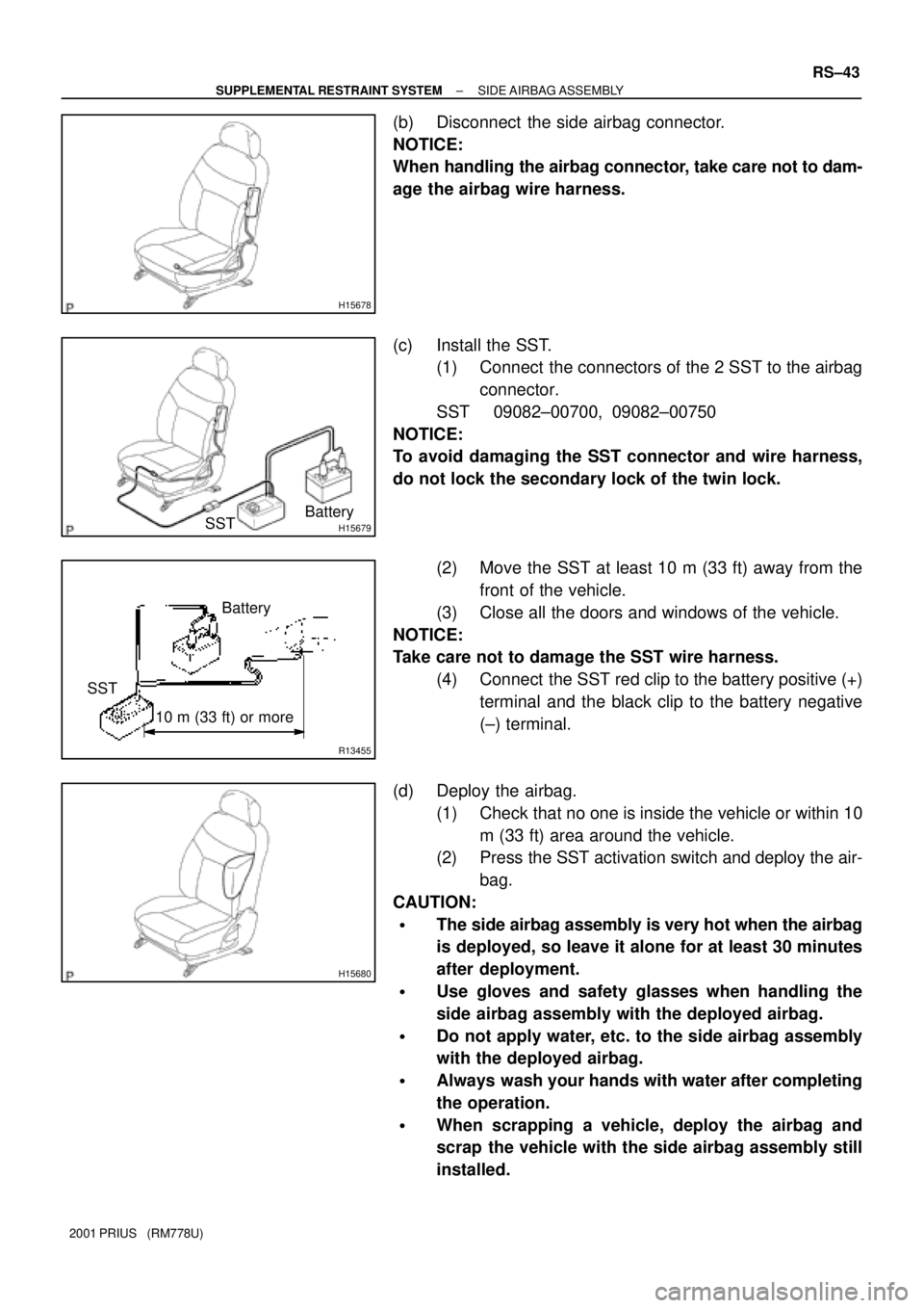
(b) Disconnect the side airbag connector.
NOTICE:
When handling the airbag connector, take care not to dam-
age the airbag wire harness.
(c) Install the SST.
(1) Connect the connectors of the 2 SST to the airbag
connector.
SST 09082±00700, 09082±00750
NOTICE:
To avoid damaging the SST connector and wire harness,
do not lock the secondary lock of the twin lock.
(2) Move the SST at least 10 m (33 ft) away from the
front of the vehicle.
(3) Close all the doors and windows of the vehicle.
NOTICE:
Take care not to damage the SST wire harness.
(4) Connect the SST red clip to the battery positive (+)
terminal and the black clip to the battery negative
(±) terminal.
(d) Deploy the airbag.
(1) Check that no one is inside the vehicle or within 10
m (33 ft) area around the vehicle.
(2) Press the SST activation switch and deploy the air-
bag.
CAUTION:
�The side airbag assembly is very hot when the airbag
is deployed, so leave it alone for at least 30 minutes
after deployment.
�Use gloves and safety glasses when handling the
side airbag assembly with the deployed airbag.
�Do not apply water, etc. to the side airbag assembly
with the deployed airbag.
�Always wash your hands with water after completing
the operation.
�When scrapping a vehicle, deploy the airbag and
scrap the vehicle with the side airbag assembly still
installed.
Page 1765 of 1943

BE±8
± BODY ELECTRICALTROUBLESHOOTING
1675 Author�: Date�:
2001 PRIUS (RM778U) Shift position indicator light does not light up.
1. ECM
2. Shift Position Sensor
3. HV ECU
4. Meter Circuit Plate
5. Wire Harness±
HT±54
±
BE±39
±
CRUISE indicator light does not light up.
1. Bulb
2. HV ECU
3. Meter Circuit Plate
4. Wire Harness±
±
BE±39
±
DEFOGGER SYSTEM
This system uses the multiplex communication system, so check diagnosis system of the multiplex commu-
nication system before you proceed with troubleshooting.
SymptomSuspect AreaSee page
Rear window defogger does not operate.
1. DEF M±Fuse
2. Defogger Relay
3. Defogger Switch (in A/C Amplifier)
4. Defogger Wire
5. Wire Harness
6. Body ECU
7. Noise Filter
8. A/C ECUBE±12
BE±49
DI±864
BE±49
±
DI±678
±
DI±864
Mirror heater does not operate.
1. M±HTR Fuse (Passenger SIde J/B)
2. Mirror Heater Relay
3. Mirror Heater
4. Wire HarnessBE±12
BE±49
BE±49
±
POWER WINDOW CONTROL SYSTEM
This system uses the multiplex communication system, so check diagnosis system of the multiplex commu-
nication system before you proceed with troubleshooting.
SymptomSuspect AreaSee page
Power window dose not operate.
1. ECU B Fuse
2. GAUGE Fuse
3. Power Main Relay
4. Ignition Switch
5. Power Window Master Switch
6. Body ECU
7. Wire HarnessBE±12
BE±12
BE±56
BE±17
BE±56
DI±678
±
Only the driver's window does not operate.
1. Power Window Master Switch
2. Power Window Switch
3. Power Window Motor
4. Wire HarnessBE±56
BE±56
BE±56
±
ºWindow lock functionº does not operate.Power Window Master SwitchBE±56
Illumination does not light up.Power Window Master SwitchBE±56
Page 1766 of 1943

± BODY ELECTRICALTROUBLESHOOTING
BE±9
1676 Author�: Date�:
2001 PRIUS (RM778U)
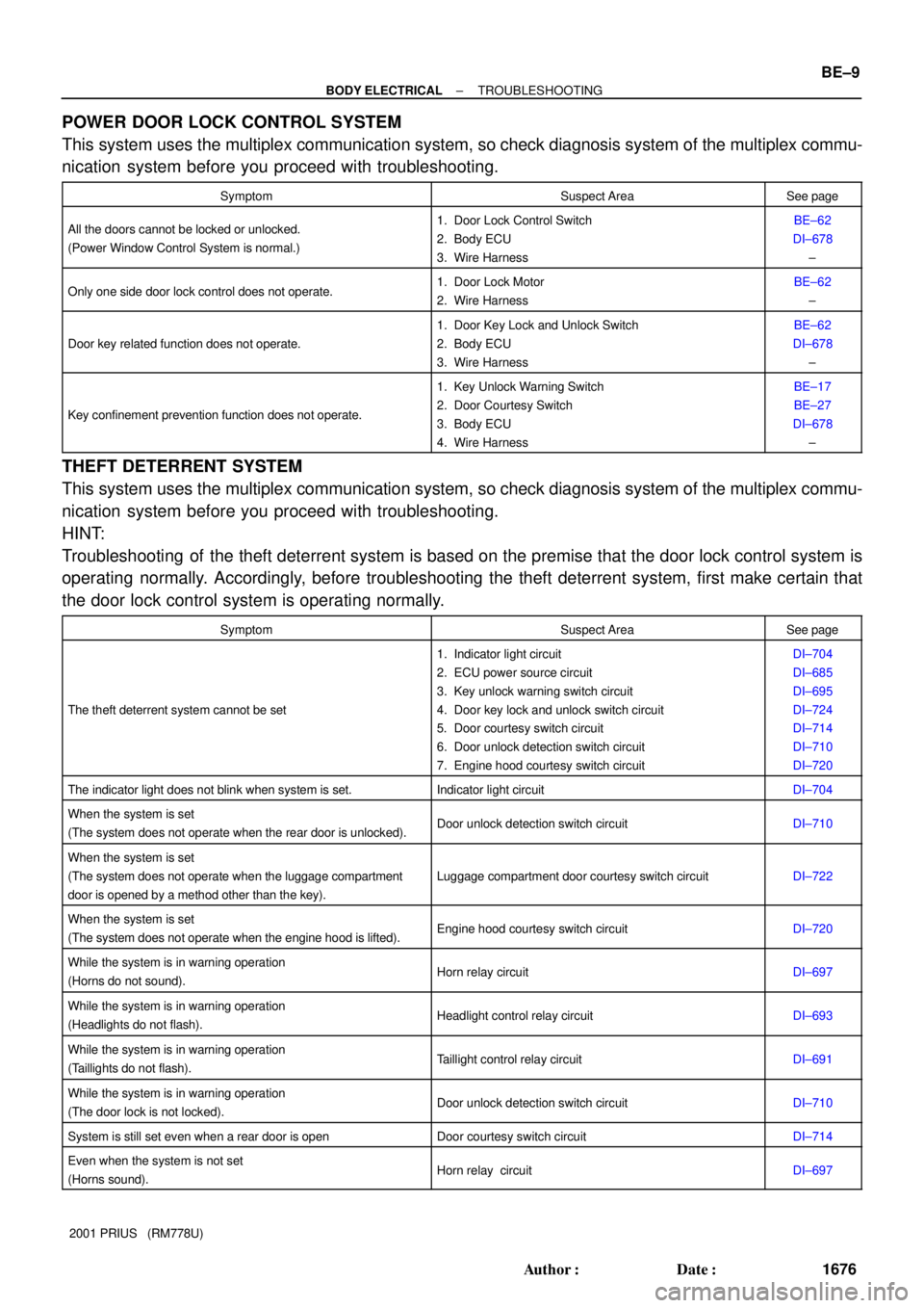
POWER DOOR LOCK CONTROL SYSTEM
This system uses the multiplex communication system, so check diagnosis system of the multiplex commu-
nication system before you proceed with troubleshooting.
SymptomSuspect AreaSee page
All the doors cannot be locked or unlocked.
(Power Window Control System is normal.)1. Door Lock Control Switch
2. Body ECU
3. Wire HarnessBE±62
DI±678
±
Only one side door lock control does not operate.1. Door Lock Motor
2. Wire HarnessBE±62
±
Door key related function does not operate.
1. Door Key Lock and Unlock Switch
2. Body ECU
3. Wire HarnessBE±62
DI±678
±
Key confinement prevention function does not operate.
1. Key Unlock Warning Switch
2. Door Courtesy Switch
3. Body ECU
4. Wire HarnessBE±17
BE±27
DI±678
±
THEFT DETERRENT SYSTEM
This system uses the multiplex communication system, so check diagnosis system of the multiplex commu-
nication system before you proceed with troubleshooting.
HINT:
Troubleshooting of the theft deterrent system is based on the premise that the door lock control system is
operating normally. Accordingly, before troubleshooting the theft deterrent system, first make certain that
the door lock control system is operating normally.
SymptomSuspect AreaSee page
The theft deterrent system cannot be set
1. Indicator light circuit
2. ECU power source circuit
3. Key unlock warning switch circuit
4. Door key lock and unlock switch circuit
5. Door courtesy switch circuit
6. Door unlock detection switch circuit
7. Engine hood courtesy switch circuitDI±704
DI±685
DI±695
DI±724
DI±714
DI±710
DI±720
The indicator light does not blink when system is set.Indicator light circuitDI±704
When the system is set
(The system does not operate when the rear door is unlocked).Door unlock detection switch circuitDI±710
When the system is set
(The system does not operate when the luggage compartment
door is opened by a method other than the key).
Luggage compartment door courtesy switch circuitDI±722
When the system is set
(The system does not operate when the engine hood is lifted).Engine hood courtesy switch circuitDI±720
While the system is in warning operation
(Horns do not sound).Horn relay circuitDI±697
While the system is in warning operation
(Headlights do not flash).Headlight control relay circuitDI±693
While the system is in warning operation
(Taillights do not flash).Taillight control relay circuitDI±691
While the system is in warning operation
(The door lock is not locked).Door unlock detection switch circuitDI±710
System is still set even when a rear door is openDoor courtesy switch circuitDI±714
Even when the system is not set
(Horns sound).Horn relay circuitDI±697
Page 1794 of 1943

BE1V2±01
I17845
Power WIndow Master Switch
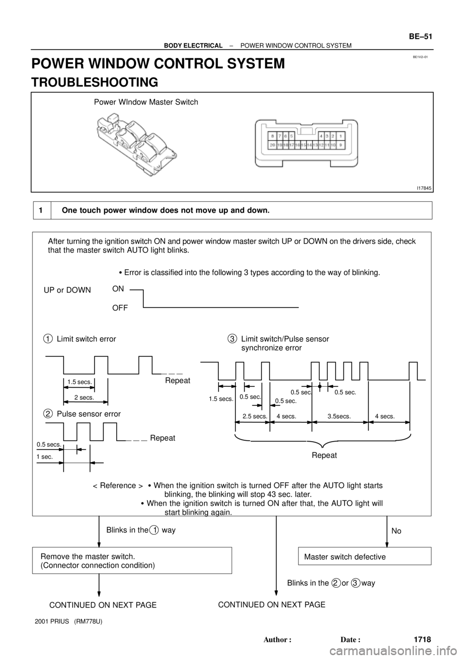
1 One touch power window does not move up and down.
After turning the ignition switch ON and power window master switch UP or DOWN on the drivers side, check
that the master switch AUTO light blinks.
� Error is classified into the following 3 types according to the way of blinking.
UP or DOWNON
OFF
1 Limit switch error 3 Limit switch/Pulse sensor
synchronize error
1.5 secs.
2 secs.Repeat
1.5 secs.0.5 sec.
No Repeat 2 Pulse sensor error
Repeat
< Reference > � When the ignition switch is turned OFF after the AUTO light starts
blinking, the blinking will stop 43 sec. later.
� When the ignition switch is turned ON after that, the AUTO light will
start blinking again.
0.5 secs.
Blinks in the 1 way
Remove the master switch.
(Connector connection condition)Master switch defective
Blinks in the 2 or 3 way
1 sec.
CONTINUED ON NEXT PAGECONTINUED ON NEXT PAGE
0.5 sec.0.5 sec. 0.5 sec.
2.5 secs. 4 secs. 4 secs.3.5secs.
± BODY ELECTRICALPOWER WINDOW CONTROL SYSTEM
BE±51
1718 Author�: Date�:
2001 PRIUS (RM778U)
POWER WINDOW CONTROL SYSTEM
TROUBLESHOOTING
Page 1795 of 1943

Master switch defective
Does continuity exist between
connector terminals on the vehicle side?
Master switch side e Motor side
12 (PLS) terminal e 3 terminal
13 (LMT) terminal e 4 terminal
11 (SGNG) terminal e 5 terminal
Does continuity exist between 11, 12,
and 13 terminals on the master switch
side or 3, 4, and 5 terminals on the
motor side and body ground?
Connect the connector of power window motor.
Connect the normal master switch, do AUTO UP
and AUTO DOWN operations work?
Power window motor defective. Ye sNoWire harness defective (open)
Wire harness defective (short) Ye s
Ye s No
No CONTINUED FROM PREVIOUS PAGE
Open the fully closed window glass of
the driver 's door and check the change
of the voltage between terminal 13 and
11 of the master switch
Fully opened: 0 V
Fully closed: 10 ± 14 VDisconnect the connecters of master
switch and driver's power window motor. CONTINUED FROM PREVIOUS PAGE
OKNG BE±52
± BODY ELECTRICALPOWER WINDOW CONTROL SYSTEM
1719 Author�: Date�:
2001 PRIUS (RM778U)
Page 1796 of 1943
When operating AUTO UP with the ignition
switch ON, is there a cause of
increasing friction resistance at
the inverse position?Disassemble the door and repair or
replace the applicable part.
Remove the power window regulator assembly.
Does the window operate smoothly
when moving the window up manually
after assembling?
Remove the power window motor from
the power window regulator assembly.
When operating the power window
regulator manually, does the regulator
move smoothly?
Are gears not damaged?
Does window motor rotate smoothly?
Reset the limit switch (See page BE±60).
Does the window move normally?
Master switch defective.Check and replace door glass run.
Power window regulator defective.
Power window motor defective.
Normal (Check the function) 2 During AUTO UP operation, the power window moves down.
Ye s
No
No
No
No
No Ye s
Ye s
Ye s
Ye s
± BODY ELECTRICALPOWER WINDOW CONTROL SYSTEM
BE±53
1720 Author�: Date�:
2001 PRIUS (RM778U)
Page 1797 of 1943
3The DOWN function does not work though some other objects are caught in the power window glass.
Is the system in the jam protection
function operating condition?
� The AUTO UP operation works with
the ignition switch ON. (One±touch operation)Normal (Perform function check)
Proceed to chart 1.
Normal
After performing operation check
repeatedly, conduct the function check. Does the AUTO UP or AUTO DOWN operation work
with the ignition switch ON?
Is the power window within the jam
protection function operating area?
< Out of the operating area >
Area around the fully closed position
Reset the limit switch (See page BE±60).
Does the power window operate normally?
Master switch defective.No
Ye s
Ye s
No No Ye s Ye s
No BE±54
± BODY ELECTRICALPOWER WINDOW CONTROL SYSTEM
1721 Author�: Date�:
2001 PRIUS (RM778U)