Page 1288 of 1943
I15516
P10
Power Window Motor
Y
G
PLS DU
DON
LMT SGND 8
20
11 O
P±L
GR 1
2
3 45P9 Power Window
Master SW
13
± DIAGNOSTICSDRIVER DOOR CONTROL SYSTEM
DI±753
2001 PRIUS (RM778U)
Jam protection pulse switch circuit
CIRCUIT DESCRIPTION
Jam protection pulse switch is built±in the power window motor. Pulse switch outputs ON/OFF pulse when
the motor rotates.
WIRING DIAGRAM
DI2BU±09
Page 1289 of 1943
DI±754
± DIAGNOSTICSDRIVER DOOR CONTROL SYSTEM
2001 PRIUS (RM778U)
INSPECTION PROCEDURE
1 Check jam protection pulse switch (See page BE±56).
NG Replace the power window motor.
OK
2 Check wireharness and connector between jam protection pulse switch and
driver door ECU.
NG Repair or replace wireharness or connector.
OK
Proceed to next circuit inspection shown on
problem symptoms table
(See page DI±734).
Page 1290 of 1943
DI1SF±03
I15526
ECM
Body ECUDLC3
Gateway ECU
Power Window Master Switch
(Driver Door Control ECU)A/C Amplifier
Combination Meter
± DIAGNOSTICSMULTIPLEX COMMUNICATION SYSTEM
DI±757
2001 PRIUS (RM778U)
PRE±CHECK
1. DIAGNOSIS SYSTEM
(a) As shown in the following illustration, each ECU of this ve-
hicle is connected by communication bus and it transmits
each signal by communication. This communication bus
is self±diagnosed by Body ECU and it memorizes DTC
when it detects communication stop to ECU or commu-
nication bus +B short or GND short. There is a possibility
that Body ECU cannot self±diagnose accurately unless
it doesn't work normal. So, please note that the trouble-
shooting of Body Electrical System should be done after
confirming if Body ECU and Open door indicator works
normal by 2. ºBASIC INSPECTIONº described later.
Page 1298 of 1943
DI1SJ±03
I15494
Body ECU P9
Power Window
Master SW
18
RX 6
B8
Y
Y5
IG1 MPX1
± DIAGNOSTICSMULTIPLEX COMMUNICATION SYSTEM
DI±767
2001 PRIUS (RM778U)
CIRCUIT INSPECTION
DTC B1211 / 11 Driver door ECU communication stop
CIRCUIT DESCRIPTION
This DTC is output when communication stops between driver door ECU and body ECU.
DTC No.DTC Detecting ConditionTrouble Area
B1211/11No communication from driver door ECU more than 10 se-�Driver door ECUB1211/11No communication from driver door ECU more than 10 se
conds.
�Driver door ECU
�Wireharness
WIRING DIAGRAM
Page 1299 of 1943
DI±768
± DIAGNOSTICSMULTIPLEX COMMUNICATION SYSTEM
2001 PRIUS (RM778U)
INSPECTION PROCEDURE
1 Check driver door ECU.
CHECK:
Check if the driver door window glass auto up.
HINT:
With this inspection, the driver door ECU CPU can be diagnosed if it works normally or not.
NG Replace the driver door ECU.
OK
Page 1367 of 1943
± DIAGNOSTICSNAVIGATION SYSTEM
DI±851
2001 PRIUS (RM778U)
9 Is there anything such as a film stuck to the window?
Yes Reception may be affected by a screen such as
a film.
No
10 Service check mode. (Is º80±40, 41º is displayed in the unit check mode of the
navigation ECU?)
Yes Troubleshoot for each diagnosis.
No
Replace the navigation antenna.
HINT:
If the trouble still occurs, replace the navigation ECU.
Page 1369 of 1943
± DIAGNOSTICSNAVIGATION SYSTEM
DI±853
2001 PRIUS (RM778U)
4 Is there anything such as a film stuck to the window?
Yes Reception may be affected by a screen such as
a film.
No
5 Service check mode. (Is º80±40, 41º is displayed in the unit check mode of the
navigation ECU?)
Yes Troubleshoot for each diagnosis.
No
Replace the navigation antenna.
HINT:
If the trouble still occurs, replace the navigation ECU.
Page 1735 of 1943

R13455
10 m (33 ft) or more
SSTBattery
R06753
RS±18
± SUPPLEMENTAL RESTRAINT SYSTEMSTEERING WHEEL PAD AND SPIRAL CABLE
2001 PRIUS (RM778U)
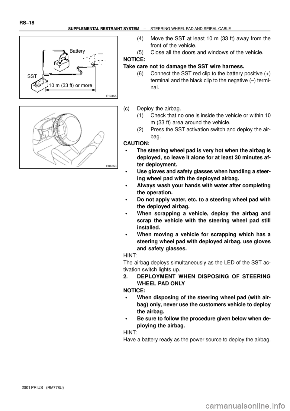
(4) Move the SST at least 10 m (33 ft) away from the
front of the vehicle.
(5) Close all the doors and windows of the vehicle.
NOTICE:
Take care not to damage the SST wire harness.
(6) Connect the SST red clip to the battery positive (+)
terminal and the black clip to the negative (±) termi-
nal.
(c) Deploy the airbag.
(1) Check that no one is inside the vehicle or within 10
m (33 ft) area around the vehicle.
(2) Press the SST activation switch and deploy the air-
bag.
CAUTION:
�The steering wheel pad is very hot when the airbag is
deployed, so leave it alone for at least 30 minutes af-
ter deployment.
�Use gloves and safety glasses when handling a steer-
ing wheel pad with the deployed airbag.
�Always wash your hands with water after completing
the operation.
�Do not apply water, etc. to a steering wheel pad with
the deployed airbag.
�When scrapping a vehicle, deploy the airbag and
scrap the vehicle with the steering wheel pad still
installed.
�When moving a vehicle for scrapping which has a
steering wheel pad with deployed airbag, use gloves
and safety glasses.
HINT:
The airbag deploys simultaneously as the LED of the SST ac-
tivation switch lights up.
2. DEPLOYMENT WHEN DISPOSING OF STEERING
WHEEL PAD ONLY
NOTICE:
�When disposing of the steering wheel pad (with air-
bag) only, never use the customers vehicle to deploy
the airbag.
�Be sure to follow the procedure given below when de-
ploying the airbag.
HINT:
Have a battery ready as the power source to deploy the airbag.