Page 627 of 1943

DI7SS±01
F02094
E7 E8 E9 E10
DI±20
± DIAGNOSTICSENGINE
2001 PRIUS (RM778U)
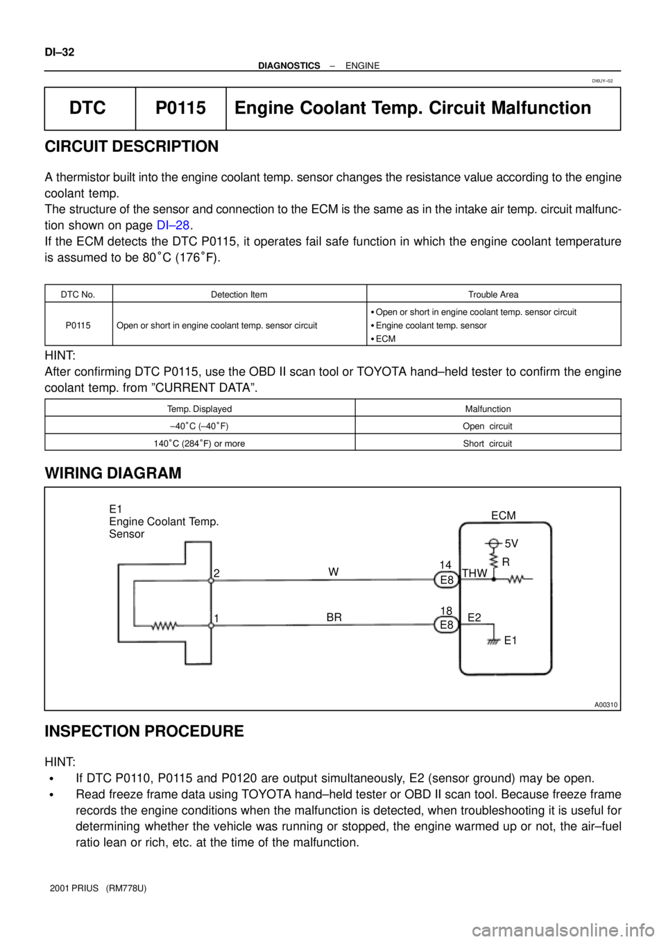
TERMINALS OF ECM
Symbols (Terminal No.)Wiring ColorConditionSTD Voltage (V)
BATT (E8 ± 3) ± E1 (E8 ± 17)R±W eBRAlways9 ± 14
+B (E8 ± 4) ± E1 (E8 ± 17)B e BRIG switch ON9 ± 14
+BM (E7 ± 6) ± E1 (E8 ± 17)GR e BRAlways9 ± 14
IGSW(E10 ± 9) ± E1(E8 ± 17)B±W e BRIG switch ON9 ± 14
MREL (E9 ± 25)
± E1(E8 ± 17)G±R e BRIG switch ON9 ± 14
VC (E8 ± 2) ± E2 (E8 ± 18)Y±R e BRIG switch ON4.5 ± 5.5
VTA (E8 23) E2 (E8 18)PBR
IG switch ON
Throttle valve fully closed0.4 ± 1.0
VTA (E8 ± 23) ± E2 (E8 ± 18)Pe BRIG switch ON
Throttle valve fully open3.2 ± 4.8
VTA2 (E8 21) E2 (E8 18)LBR
IG switch ON
Accelerator pedal released2.0 ± 2.9
VTA2 (E8 ± 21) ± E2 (E8 ± 18)Le BRIG switch ON
Accelerator pedal depressed4.6 ± 5.1
VG (E8 ± 10) ± EVG (E8 ± 19)G eRIdling, A/C switch OFF, Shift position in N or P position0.5 ± 3.0
THA (E8 ± 22) ± E2 (E8 ± 18)R±B eBRIdling, Intake air temp. 20°C (68°F)0.5 ± 3.4
THW (E8 ± 14) ± E2 (E8 ± 18)W eBRIdling, Engine coolant temp. 80°C (176°F) 0.2 ± 1.0
IG switch ON9 ± 14
#10 (E8 ± 5) ± E01 (E7 ± 21)Y eW±BIdlingPulse generation
(See page DI±65)
IG switch ON9 ± 14
#20 (E8 ± 6) ± E01 (E7 ± 21)B±R eW±BIdlingPulse generation
(See page DI±65)
IG switch ON9 ± 14
#30 (E7 ± 1) ± E01 (E7 ± 21)L±W eW±BIdlingPulse generation
(See page DI±65)
IG switch ON9 ± 14
#40 (E7 ± 2) ± E01 (E7 ± 21)R±W eW±BIdlingPulse generation
(See page DI±65)
IGT1 (E7 ± 11) ± E1 (E8 ± 17)Y±G eBRIdlingPulse generation
(See page DI±115)
IGT2 (E7 ± 12) ± E1 (E8 ± 17)W eBRIdlingPulse generation
(See page DI±115)
IGT3 (E7 ± 13) ± E1 (E8 ± 17)G eBRIdlingPulse generation
(See page DI±115)
Page 637 of 1943

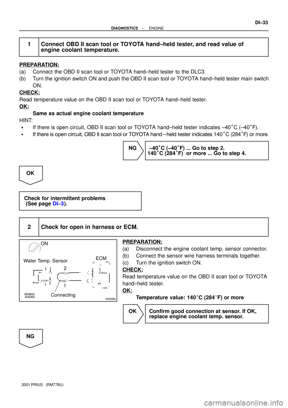
A00310
E1
Engine Coolant Temp.
Sensor
2
1ECM
W
BR14
E8
E8185V
THW
E2
E1 R DI±32
± DIAGNOSTICSENGINE
2001 PRIUS (RM778U)
DTC P0115 Engine Coolant Temp. Circuit Malfunction
CIRCUIT DESCRIPTION
A thermistor built into the engine coolant temp. sensor changes the resistance value according to the engine
coolant temp.
The structure of the sensor and connection to the ECM is the same as in the intake air temp. circuit malfunc-
tion shown on page DI±28.
If the ECM detects the DTC P0115, it operates fail safe function in which the engine coolant temperature
is assumed to be 80°C (176°F).
DTC No.Detection ItemTrouble Area
P0115Open or short in engine coolant temp. sensor circuit
�Open or short in engine coolant temp. sensor circuit
�Engine coolant temp. sensor
�ECM
HINT:
After confirming DTC P0115, use the OBD II scan tool or TOYOTA hand±held tester to confirm the engine
coolant temp. from ºCURRENT DATAº.
Temp. DisplayedMalfunction
±40°C (±40°F)Open circuit
140°C (284°F) or moreShort circuit
WIRING DIAGRAM
INSPECTION PROCEDURE
HINT:
�If DTC P0110, P0115 and P0120 are output simultaneously, E2 (sensor ground) may be open.
�Read freeze frame data using TOYOTA hand±held tester or OBD II scan tool. Because freeze frame
records the engine conditions when the malfunction is detected, when troubleshooting it is useful for
determining whether the vehicle was running or stopped, the engine warmed up or not, the air±fuel
ratio lean or rich, etc. at the time of the malfunction.
DI6UY±02
Page 638 of 1943

BE6653
A00365
A00366
ON
ECM
2
1 Water Temp. Sensor
Connecting
± DIAGNOSTICSENGINE
DI±33
2001 PRIUS (RM778U)
1 Connect OBD II scan tool or TOYOTA hand±held tester, and read value of
engine coolant temperature.
PREPARATION:
(a) Connect the OBD II scan tool or TOYOTA hand±held tester to the DLC3.
(b) Turn the ignition switch ON and push the OBD II scan tool or TOYOTA hand±held tester main switch
ON.
CHECK:
Read temperature value on the OBD II scan tool or TOYOTA hand±held tester.
OK:
Same as actual engine coolant temperature
HINT:
�If there is open circuit, OBD II scan tool or TOYOTA hand±held tester indicates ±40°C (±40°F).
�If there is open circuit, OBD II scan tool or TOYOTA hand-held tester indicates 140°C (284°F) or more.
NG ±40°C (±40°F) ... Go to step 2.
140°C (284°F) or more ... Go to step 4.
OK
Check for intermittent problems
(See page DI±3).
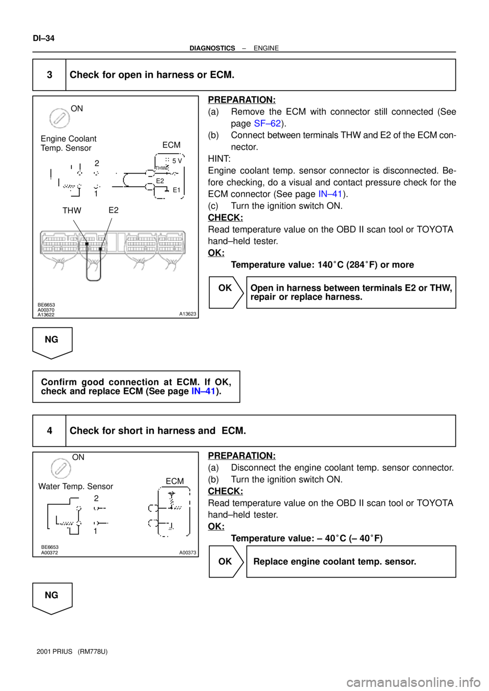
2 Check for open in harness or ECM.
PREPARATION:
(a) Disconnect the engine coolant temp. sensor connector.
(b) Connect the sensor wire harness terminals together.
(c) Turn the ignition switch ON.
CHECK:
Read temperature value on the OBD II scan tool or TOYOTA
hand±held tester.
OK:
Temperature value: 140°C (284°F) or more
OK Confirm good connection at sensor. If OK,
replace engine coolant temp. sensor.
NG
Page 639 of 1943

BE6653
A00370
A13622A13623
ON
Engine Coolant
Temp. Sensor
12
THWE2
ECM
5 V
E2THW
E1
BE6653
A00372A00373
ON
2
1ECM
Water Temp. Sensor
DI±34
± DIAGNOSTICSENGINE
2001 PRIUS (RM778U)
3 Check for open in harness or ECM.
PREPARATION:
(a) Remove the ECM with connector still connected (See
page SF±62).
(b) Connect between terminals THW and E2 of the ECM con-
nector.
HINT:
Engine coolant temp. sensor connector is disconnected. Be-
fore checking, do a visual and contact pressure check for the
ECM connector (See page IN±41).
(c) Turn the ignition switch ON.
CHECK:
Read temperature value on the OBD II scan tool or TOYOTA
hand±held tester.
OK:
Temperature value: 140°C (284°F) or more
OK Open in harness between terminals E2 or THW,
repair or replace harness.
NG
Confirm good connection at ECM. If OK,
check and replace ECM (See page IN±41).
4 Check for short in harness and ECM.
PREPARATION:
(a) Disconnect the engine coolant temp. sensor connector.
(b) Turn the ignition switch ON.
CHECK:
Read temperature value on the OBD II scan tool or TOYOTA
hand±held tester.
OK:
Temperature value: ± 40°C (± 40°F)
OK Replace engine coolant temp. sensor.
NG
Page 640 of 1943
A09085A09091
ON
Engine Coolant
Temp. Sensor
E8 Connector
ECM
5 V
E2THW
E1
± DIAGNOSTICSENGINE
DI±35
2001 PRIUS (RM778U)
5 Check for short in harness or ECM.
PREPARATION:
(a) Remove the ECM with connector still connected (See
page SF±62).
(b) Disconnect the E8 connector of the ECM.
HINT:
Engine coolant temp. sensor connector is disconnected.
(c) Turn the ignition switch ON.
CHECK:
Read temperature value on the OBD II scan tool or TOYOTA
hand±held tester.
OK:
Temperature value: ±40°C (±40°F)
OK Repair or replace harness or connector.
NG
Check and replace ECM (See page IN±41).
Page 641 of 1943

DI±36
± DIAGNOSTICSENGINE
2001 PRIUS (RM778U)
DTC P0116 Engine Coolant Temp. Circuit Range/
Performance Problem
CIRCUIT DESCRIPTION
Refer to DTC P0115 on page DI±32.
DTC No.DTC Detecting ConditionTrouble Area
When the engine starts, the water temp. is ±7°C (20°F) or
less. And, 20 min. or more after the engine starts, the engine
temp. sensor value is 5°C (41°F) or less (2 trip detection logic)
When the engine starts, the water temp. is between ±7°C
(20°F) and 10°C (50°F). And, 5 min. or more after the engine
starts, the engine coolant temp. sensor value is 5°C (41°F) or
less. (2 trip detection logic)
P0116When the fluctuations in the engine coolant tempeerature are
within 3 °C (37 °F)before and afrer the follwing conditions are
met:
1. IDL OFF time � 250 sec.
2. Vehicle speed change of 30 km/h (19 mph) or more occurs
10 times or more.
3. 35 °C (95 °F) � Engine coolant temperature when the
ignition switch is turned ON < 60 °C (140 °F)
4. Intake air temperature after starting the engine � ±6.7 °C
(20 °F)�Engine coolant temp. sensor
�Cooling system
INSPECTION PROCEDURE
HINT:
�If DTC P0115 and P0116 are output simultaneously, engine coolant temp. sensor circuit may be open.
Perform troubleshooting of DTC P0115 first.
�Read freeze frame data using TOYOTA hand±held tester or OBD II scan tool. Because freeze frame
records the engine conditions when the malfunction is detected, when troubleshooting it is useful for
determining whether the vehicle was running or stopped, the engine warmed up or not, the air±fuel
ratio lean or rich, etc. at the time of the malfunction.
1 Are there any other codes (besides DTC P0116) being output?
YES Go to relevant DTC chart.
NO
DI6UZ±03
Page 642 of 1943
± DIAGNOSTICSENGINE
DI±37
2001 PRIUS (RM778U)
2 Check thermostat (See page CO±9).
NG Replace thermostat.
OK
Replace engine coolant temp. sensor.
Page 664 of 1943

± DIAGNOSTICSENGINE
DI±61
2001 PRIUS (RM778U)
DTC P0171 System too Lean (Fuel Trim)
DTC P0172 System too Rich (Fuel Trim)
CIRCUIT DESCRIPTION
Fuel trim refers to the feedback compensation value compared against the basic injection time. Fuel trim
includes short±term fuel trim and long±term fuel trim.
Short±term fuel trim is the short±term fuel compensation used to maintain the air±fuel ratio at its ideal
theoretical value. The signal from the oxygen sensor indicates whether the air±fuel ratio is RICH or LEAN
compared to the ideal theoretical value, triggering a reduction in fuel volume if the air±fuel ratio is rich, and
an increase in fuel volume if it is lean.
Long±term fuel trim is overall fuel compensation carried out long±term to compensate for continual deviation
of the short±term fuel trim from the central value due to individual engine differences, wear over time and
changes in the usage environment.
If both the short±term fuel trim and long±term fuel trim are LEAN or RICH beyond a certain value, it is
detected as a malfunction and the MIL lights up.
DTC No.DTC Detecting ConditionTrouble Area
P0171
When the air±fuel ratio feedback is stable after engine warming
up, the fuel trim is considerably in error on the RICH side
(2 trip detection logic)
�Air induction system
�Injector blockage
�Mass air flow meter
�Engine coolant temp. sensor
�Fuel pressure
�Gas leakage on exhaust system
�Open or short in heated oxygen sensor (bank 1 sensor 1)
circuit
�Heated oxygen sensor (bank 1 sensor 1)
P0172
When air fuel ratio feedback is stable after warming up engine,
the fuel trim is considerably in error on LEAN side (2 trip detec-
tion logic)
�Injector leak, blockage
�Mass air flow meter
�Engine coolant temp. sensor
�Ignition system
�Fuel pressure
�Gas leakage on exhaust system
�Open or short in heated oxygen sensor (bank 1, 2 sensor 1)
circuit
�Heated oxygen sensor (bank 1, 2 sensor 1)
�ECM
HINT:
�When DTC P0171 is recorded, the actual air±fuel ratio is on the LEAN side. When DTC P0172 is re-
corded, the actual air±fuel ratio is on the RICH side.
�If the vehicle runs out of fuel, the air±fuel ratio is LEAN and DTC P0171 is recorded. The MIL then
comes on.
�If the total of the short±term fuel trim value and long±term fuel trim value is within + 38 %, the system
is functioning normally.
�The oxygen sensor output voltage and the short±term fuel trim value can be read using the OBD II scan
tool or TOYOTA hand±held tester.
DI6V7±02