Page 428 of 1943
 Room Temperature Sensor
T")
BODY ELECTRICAL ± AIR CONDITIONING
182BE24Room Temperature
Sensor
182BE25
Evaporator Temperature
Sensor
182BE26
Solar Sensor
182BE27
Engine Coolant
Temperature Sensor 166
2) Room Temperature Sensor
The room temperature sensor has been pro-
vided inside the instrument finish lower panel.
The signals from this sensor are directly trans-
mitted to the air conditioning ECU.
3) Evaporator Temperature Sensor
The evaporator temperature sensor has been
provided behind the evaporator in the air
conditioning unit.
The signals from this sensor are directly trans-
mitted to the air conditioning ECU.
4) Solar Sensor
The solar sensor has been provided on top of
the instrument panel.
The signals from this sensor are directly trans-
mitted to the air conditioning ECU.
5) Engine Coolant Temperature Sensor
The water temperature sensor has been pro-
vided on the water outlet area on the left side
of the engine.
The signals from this sensor are transmitted to
the air conditioning ECU via the ECM.
Page 429 of 1943

BODY ELECTRICAL ± AIR CONDITIONING
182BE50
Large
Target
Damper
Opening
Angle
Small
Large Small
Tentative Damper Opening Angle167
Calculation of Required Outlet Air Temperature (TAO: Temperature Air Outlet)
After receiving the signals from the sensors and the temperature control switch setting, the air conditioning
ECU uses the formula shown below to calculate the required outlet air temperature, to regulate the servomo-
tors and blower motor. This is an outlet air temperature that is required in maintaining the set temperature
in a stable manner.
TAO=KSETx TSET±Kr x TR±KAMx TAMdisp±KsxTS+C±TCTA O = KSET x TSET ± Kr x TR ± KAM x TAMdisp ± Ks x TS + C ± TC
KSET= Setting Temperature Coefficient TSET = Setting Temperature
Kr = Room Air Temperature Coefficient TR = Room Air TemperatureKr= Room Air Temperature CoefficientTR= Room Air Temperature
K
AM= Ambient Air Temperature Coefficient TAMdisp = Ambient Air TemperatureAMppp
Ks = Solar Radiation Coefficient TS = Solar Radiation
C = Correct Constant TC = Compressor ON / OFF CorrectC= Correct ConstantTC= Compressor ON / OFF Correct
= Constant
Temperature Control System
1) Air Mix Damper Control
In response to the temperature control switch setting, the required ambient temperature, evaporator tem-
perature sensor, and engine coolant temperature sensor compensations are used by the air mix damper
control to calculate a tentative damper opening angle, through an arithmetic circuit in the air mix damper,
to arrive at a target damper opening angle.
� Calculating the Target Damper Opening �
Page 430 of 1943
![TOYOTA PRIUS 2001 Service Repair Manual BODY ELECTRICAL ± AIR CONDITIONING
174BE06
Ex-HI
Blower
Air
Volume
LO
Low
Required Outlet
Air TemperatureHigh[�C]
174BE07
HI
Calculated
Air Volume
LO
OFF[�C]
Coolant Temperature (a) (b) (c) 168
Blowe](/manual-img/14/57461/w960_57461-429.png "TOYOTA PRIUS 2001 Service Repair Manual BODY ELECTRICAL ± AIR CONDITIONING
174BE06
Ex-HI
Blower
Air
Volume
LO
Low
Required Outlet
Air TemperatureHigh[�C]
174BE07
HI
Calculated
Air Volume
LO
OFF[�C]
Coolant Temperature (a) (b) (c) 168
Blowe")
BODY ELECTRICAL ± AIR CONDITIONING
174BE06
Ex-HI
Blower
Air
Volume
LO
Low
Required Outlet
Air TemperatureHigh[�C]
174BE07
HI
Calculated
Air Volume
LO
OFF[�C]
Coolant Temperature (a) (b) (c) 168
Blower Control System
1) Blower Motor Startup Control
When the blower motor is started up, the blower voltage in the auto mode (low speed) is output to the
blower controller for 3 seconds. This is designed to protect the blower controller from a sudden startup
current surge.
2) Manual Control
Sets the blower speed according to operation of the blower switch.
3) Automatic Control
a. Stepless Air Volume Control
As shown on the right, when the AUTO
switch on the heater control panel is pushed,
the air conditioning ECU automatically reg-
ulates the voltage to the blower controller, in
accordance with the required outlet air tem-
perature, to deliver stepless air volume.
b. Warm-Up Control
When the coolant temperature detected by the engine coolant temperature sensor is below a predeter-
mined level and the air outlet is in the FOOT or BI-LEVEL mode, the blower does not operate. When
the coolant temperature reaches specified temperature (b), the blower motor operates at low speed.
When the coolant temperature is between specified temperature (b) to (c), the air flow calculation using
the engine coolant temperature sensor signal, and, the air flow calculation using the required outlet air
temperature are compared, and the lesser of the two is automatically selected as the air flow to be used.
When the coolant temperature reaches specified temperature (c) or more, the blower motor runs at high
speed. Moreover, when the coolant temperature is under specified temperature (a), and the warm-up
control is effected (blower motor off), the air outlet is switched to the DEF mode. Later, when the blower
motor turns on, the air outlet changes from the DEF mode to the FOOT or BI-LEVEL mode.
Page 490 of 1943

� DTC No.
Indicates the diagnostic trouble code.
� Page or Instructions
Indicates the page where the inspection procedure
for each circuit is to be found, or gives instructions
for checking and repairs.
� Detection Item
Indicates the system of the problem or
contents of the problem.� Trouble Area
Indicates the suspect area of the
problem.
Mass Air Flow Circuit MalfunctionDetection Item
� Open or short in mass air flow meter circuit
� Mass air flow meter
� ECM DTC No.
(See page)Trouble AreaMIL* MemoryP0100
(DI±24)
P0101
(DI±28)
P0115
(DI±33)� Open or short in intake air temp. sensor
circuit
� Intake air temp. sensor
� ECM Intake Air Temp. Circuit
Malfunction P0110
(DI±29)
� Open or short in engine coolant temp. sensor circuit
� Engine coolant temp. sensor
� ECM
Throttle/ Pedal Position Sensor/Switch
ºAº Circuit MalfunctionEngine Coolant Temp.
Circuit Malfunction
� Open or short in throttle position sensor circuit
� Throttle position sensor
� ECM
DTC CHART (SAE Controlled)
HINT:
Parameters listed in the chart may not be exactly the same as your reading due to the type of instrument or other
factors.
If a malfunction code is displayed during the DTC check mode, check the circuit for that code listed in the table
below. For details of each code, turn to the page referred to under the ºSee pageº for the respective ºDTC No.º
in the DTC chart.
Mass Air Flow Circuit
Range/ Performance Problem� Mass air flow meter
� Throttle position sensor Throttle/ Pedal Position Sensor/ Switch
ºAº Circuit Range / Performance Prob-
lem P0116
(DI±37)Engine Coolant Temp.
Circuit Range/ Performance Problem� Engine coolant temp. sensor
� Cooling system
± INTRODUCTIONHOW TO TROUBLESHOOT ECU CONTROLLED
SYSTEMSIN±37
2001 PRIUS (RM778U)
4. DIAGNOSTIC TROUBLE CODE CHART
The inspection procedure is shown in the table below. This table permits efficient and accurate troubleshoot-
ing using the diagnostic trouble codes displayed in the diagnostic trouble code check. Proceed with trouble-
shooting in accordance with the inspection procedure given in the diagnostic chart corresponding to the
diagnostic trouble codes displayed. The engine diagnostic trouble code chart is shown below as an example.
Page 504 of 1943

GLOSSARY OF SAE AND TOYOTA TERMS
This glossary lists all SAE±J1930 terms and abbreviations used in this manual in compliance with SAE rec-")
IN0CI±02
± INTRODUCTIONTERMS
IN±51
2001 PRIUS (RM778U)
GLOSSARY OF SAE AND TOYOTA TERMS
This glossary lists all SAE±J1930 terms and abbreviations used in this manual in compliance with SAE rec-
ommendations, as well as their TOYOTA equivalents.
SAE
ABBREVIATIONSSAE TERMSTOYOTA TERMS
( )±±ABBREVIATIONS
A/CAir ConditioningAir Conditioner
ACLAir CleanerAir Cleaner, A/CL
AIRSecondary Air InjectionAir Injection (AI)
APAccelerator Pedal±
B+Battery Positive Voltage+B, Battery Voltage
BAROBarometric PressureHAC
CACCharge Air CoolerIntercooler
CARBCarburetorCarburetor
CFIContinuous Fuel Injection±
CKPCrankshaft PositionCrank Angle
CLClosed LoopClosed Loop
CMPCamshaft PositionCam Angle
CPPClutch Pedal Position±
CTOXContinuous Trap Oxidizer±
CTPClosed Throttle PositionLL ON, Idle ON
DFIDirect Fuel Injection (Diesel)Direct Injection (DI)
DIDistributor Ignition±
DLC1
DLC2
DLC3Data Link Connector 1
Data Link Connector 2
Data Link Connector 31: Check Connector
2: Total Diagnosis Comunication Link (TDCL)
3: OBD II Diagnostic Connector
DTCDiagnostic Trouble CodeDiagnostic Code
DTMDiagnostic Test Mode±
ECLEngine Control Level±
ECMEngine Control ModuleEngine ECU (Electronic Control Unit)
ECTEngine Coolant TemperatureCoolant Temperature, Water Temperature (THW)
EEPROMElectrically Erasable Programmable Read Only Memory
Electrically Erasable Programmable Read Only Memory
(EEPROM),
Erasable Programmable Read Only Memory (EPROM)
EFEEarly Fuel EvaporationCold Mixture Heater (CMH), Heat Control Valve (HCV)
EGRExhaust Gas RecirculationExhaust Gas Recirculation (EGR)
EIElectronic IgnitionTOYOTA Distributorless Ignition (TDI)
EMEngine ModificationEngine Modification (EM)
EPROMErasable Programmable Read Only MemoryProgrammable Read Only Memory (PROM)
EVAPEvaporative EmissionEvaporative Emission Control (EVAP)
FCFan Control±
FEEPROMFlash Electrically Erasable Programmable
Read Only Memory±
FEPROMFlash Erasable Programmable Read Only Memory±
FFFlexible Fuel±
FPFuel PumpFuel Pump
GENGeneratorAlternator
GNDGroundGround (GND)
Page 510 of 1943

UNDER HOOD
GENERAL MAINTENANCE
1. GENERAL NOTES
�Maintenance items may vary from country to country. Check the owner")
MA02G±02
MA±4
± MAINTENANCEUNDER HOOD
57 Author�: Date�:
2001 PRIUS (RM778U)
UNDER HOOD
GENERAL MAINTENANCE
1. GENERAL NOTES
�Maintenance items may vary from country to country. Check the owner's manual supplement in which
the maintenance schedule is shown.
�Every serice item in the periodic maintenance schedule must be performed.
�Periodic maintenance service must be performed according to whichever interval in the periodic main-
tenance schedule occurs first, the odometer reading (miles) or the time interval (months).
�Maintenance service after the last period should be performed at the same interval as before unless
otherwise noted.
2. WINDSHIELD WASHER FLUID
Check that there is sufficient fluid in the tank.
3. ENGINE COOLANT LEVEL
Check that the coolant level is between the ºFULLº and ºLOWº lines on the see±through reservoir.
4. RADIATOR AND HOSES
(a) Check that the front of the radiator is clean and not blocked with leaves, dirt or bugs.
(b) Check the hoses for cracks, kinks, rot or loose connections.
5. BRAKE FLUID LEVELS
Check that the brake fluid levels are near the upper level line on the see±through reservoirs.
6. CHECK TRANSAXLE OIL (FLUID)
�Visually check the transaxle for oil (fluid) leakage.
�If leakage is found, check for the cause and repair.
HINT:
Wait until the engine and motor cools down (approx. 30 min.) before checking the fluid level after extended
driving at high speeds, in hot weather, in heavy traffic or pulling a trailer.
Page 511 of 1943
MA00R±17
B08810
± MAINTENANCEENGINE
MA±5
58 Author�: Date�:
2001 PRIUS (RM778U)
ENGINE
INSPECTION
HINT:
Inspect these items when the engine is cold.
1. INSPECT DRIVE BELT
(See page CO±4)
2. REPLACE SPARK PLUGS
(See page IG±1)
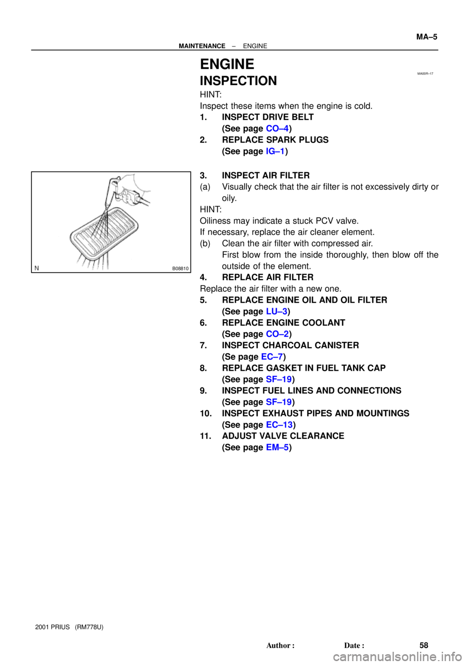
3. INSPECT AIR FILTER
(a) Visually check that the air filter is not excessively dirty or
oily.
HINT:
Oiliness may indicate a stuck PCV valve.
If necessary, replace the air cleaner element.
(b) Clean the air filter with compressed air.
First blow from the inside thoroughly, then blow off the
outside of the element.
4. REPLACE AIR FILTER
Replace the air filter with a new one.
5. REPLACE ENGINE OIL AND OIL FILTER
(See page LU±3)
6. REPLACE ENGINE COOLANT
(See page CO±2)
7. INSPECT CHARCOAL CANISTER
(Se page EC±7)
8. REPLACE GASKET IN FUEL TANK CAP
(See page SF±19)
9. INSPECT FUEL LINES AND CONNECTIONS
(See page SF±19)
10. INSPECT EXHAUST PIPES AND MOUNTINGS
(See page EC±13)
11. ADJUST VALVE CLEARANCE
(See page EM±5)
Page 528 of 1943
PP2FI±03
PP±14
± PREPARATIONCOOLING
2001 PRIUS (RM778U)
COOLANT
ItemCapacityClassification
Engine coolant4.9 liters (5.2 US qts, 4.3 lmp. qts)Ethylene±glycol base

COOLANT
ItemCapacityClassification
Engine coolant4.9 liters (5.2 US qts, 4.3 lmp. qts)Ethylene±glycol base")