Page 470 of 1943
B04751
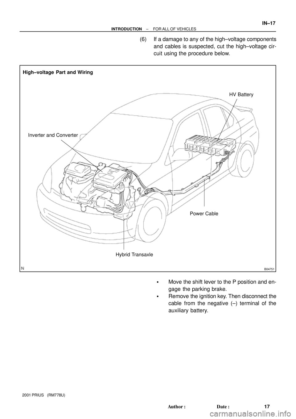
High±voltage Part and Wiring
Inverter and ConverterHV Battery
Power Cable
Hybrid Transaxle
± INTRODUCTIONFOR ALL OF VEHICLES
IN±17
17 Author�: Date�:
2001 PRIUS (RM778U)
(6) If a damage to any of the high±voltage components
and cables is suspected, cut the high±voltage cir-
cuit using the procedure below.
�Move the shift lever to the P position and en-
gage the parking brake.
�Remove the ignition key. Then disconnect the
cable from the negative (±) terminal of the
auxiliary battery.
Page 471 of 1943
B04757
B04752
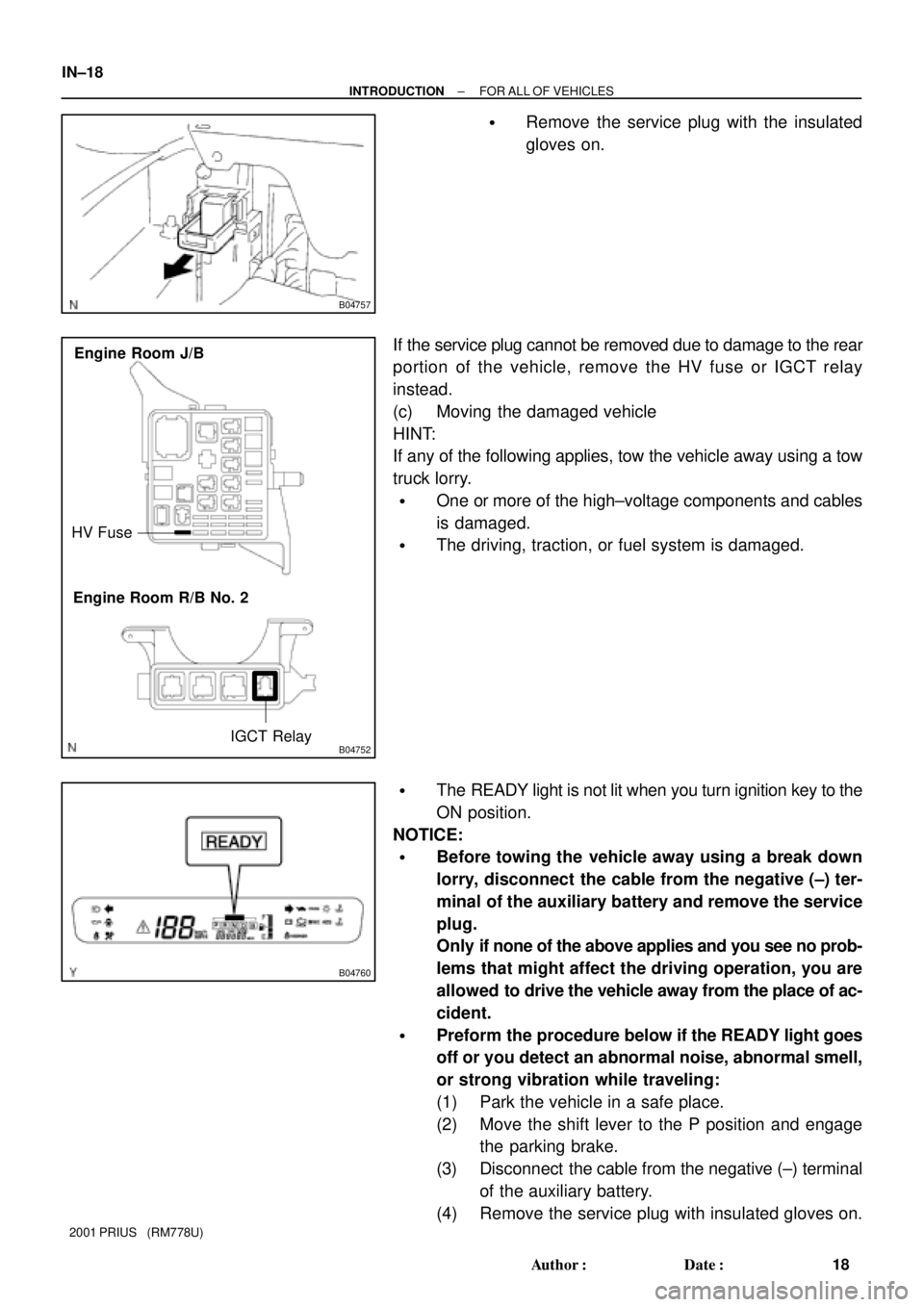
HV Fuse
IGCT Relay Engine Room J/B
Engine Room R/B No. 2
B04760
IN±18
± INTRODUCTIONFOR ALL OF VEHICLES
18 Author�: Date�:
2001 PRIUS (RM778U)
�Remove the service plug with the insulated
gloves on.
If the service plug cannot be removed due to damage to the rear
portion of the vehicle, remove the HV fuse or IGCT relay
instead.
(c) Moving the damaged vehicle
HINT:
If any of the following applies, tow the vehicle away using a tow
truck lorry.
�One or more of the high±voltage components and cables
is damaged.
�The driving, traction, or fuel system is damaged.
�The READY light is not lit when you turn ignition key to the
ON position.
NOTICE:
�Before towing the vehicle away using a break down
lorry, disconnect the cable from the negative (±) ter-
minal of the auxiliary battery and remove the service
plug.
Only if none of the above applies and you see no prob-
lems that might affect the driving operation, you are
allowed to drive the vehicle away from the place of ac-
cident.
�Preform the procedure below if the READY light goes
off or you detect an abnormal noise, abnormal smell,
or strong vibration while traveling:
(1) Park the vehicle in a safe place.
(2) Move the shift lever to the P position and engage
the parking brake.
(3) Disconnect the cable from the negative (±) terminal
of the auxiliary battery.
(4) Remove the service plug with insulated gloves on.
Page 473 of 1943
B04758
IN±20
± INTRODUCTIONFOR ALL OF VEHICLES
20 Author�: Date�:
2001 PRIUS (RM778U)
(6) If a damage to any of the high±voltage components
and cables is suspected, cut the high±voltage cir-
cuit using the procedure below:
�Move the shift lever to the P position and en-
gage the parking brake.
�Remove the ignition key. Then disconnect the
cable from the negative (±) terminal of the
auxiliary battery.
�Wear insulated gloves, and then remove the
service plug.
�If you cannot remove the service plug due to
damage to the rear portion of the vehicle, re-
move the HV fuse or IGCT relay instead.
(g) Precautions to be taken when disposing of the vehicle
When scrapping the vehicle, remove the HV battery from
the vehicle and return it through the route specified by the
manufacturer. The same applies to any damaged HV bat-
tery.
(h) Precautions to be observed when towing
Tow the damaged vehicle with its front wheels or its front
and rear wheels lifted off the ground.
NOTICE:
Towing the damaged vehicle with its front wheels on the
ground may cause the motor to generate electricity. This
electricity could, depending on the nature of the damage,
leak and cause a fire.
(i) Towing with 4 wheels on the ground
NOTICE:
�If you have to tow the damaged vehicle using a rope,
do it at a speed below 30 km/h. Such towing operation
is allowed only to cover very short distance, such as
the distance to a tow truck lorry, for example.
�Set the ignition switch to the ACC position and shift
lever to the N position.
�If you detect any abnormality in the damaged vehicle
during the towing operation, stop the towing opera-
tion immediately.
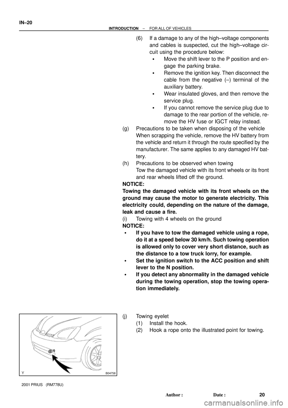
(j) Towing eyelet
(1) Install the hook.
(2) Hook a rope onto the illustrated point for towing.
Page 499 of 1943

IN04Q±11
IN±46
± INTRODUCTIONTERMS
46 Author�: Date�:
2001 PRIUS (RM778U)
TERMS
ABBREVIATIONS USED IN THIS MANUAL
AbbreviationsMeaning
ABSAnti±Lock Brake System
ACAlternating Current
ACCAccessory
ACISAcoustic Control Induction System
ACSDAutomatic Cold Start Device
A.D.D.Automatic Disconnecting Differential
A/FAir±Fuel Ratio
AHCActive Height Control Suspension
ALRAutomatic Locking Retractor
ALTAlternator
AMPAmplifier
ANTAntenna
APPROX.Approximately
A/TAutomatic Transmission (Transaxle)
AT FAutomatic Transmission Fluid
AUTOAutomatic
AUXAuxiliary
AV GAverage
AV SAdaptive Variable Suspension
BABrake Assist
BACSBoost Altitude Compensation System
BATBattery
BDCBottom Dead Center
B/LBi±Level
B/SBore±Stroke Ratio
BTDCBefore Top Dead Center
BVSVBimetallic Vacuum Switching Valve
Calif.California
CBCircuit Breaker
CCoCatalytic Converter For Oxidation
CDCompact Disc
CFCornering Force
CGCenter Of Gravity
CHChannel
COMB.Combination
CPECoupe
CPSCombustion Pressure Sensor
CPUCentral Processing Unit
CRSChild Restraint System
CTRCenter
C/VCheck Valve
CVControl Valve
Page 595 of 1943
SS1HH±02
SS±20
± SERVICE SPECIFICATIONSHYBRID VEHICLE CONTROL
142 Author�: Date�:
2001 PRIUS (RM778U)
HYBRID VEHICLE CONTROL
SERVICE DATA
HV battery therm-
istor
Resistance at 25 °C (77 °F)
1 e 2
3 e 4
5 e 6
7 e 8
9 e 10
9 ± 11 kW
9 ± 11 kW
9 ± 11 kW
9 ± 11 kW
9 ± 11 kW
ConverterOutput current100 A or less
Water temperature
switchat 48 °C (118.4 °F) or less
at more than 55 °C (131 °F)No continuity
Continuity
Service plugService plug lever Close
Stand upContinuity
No continuity
Auxiliary batteryVoltage at 20 °C (68 °F)12.5 ± 12.9 V
Page 775 of 1943
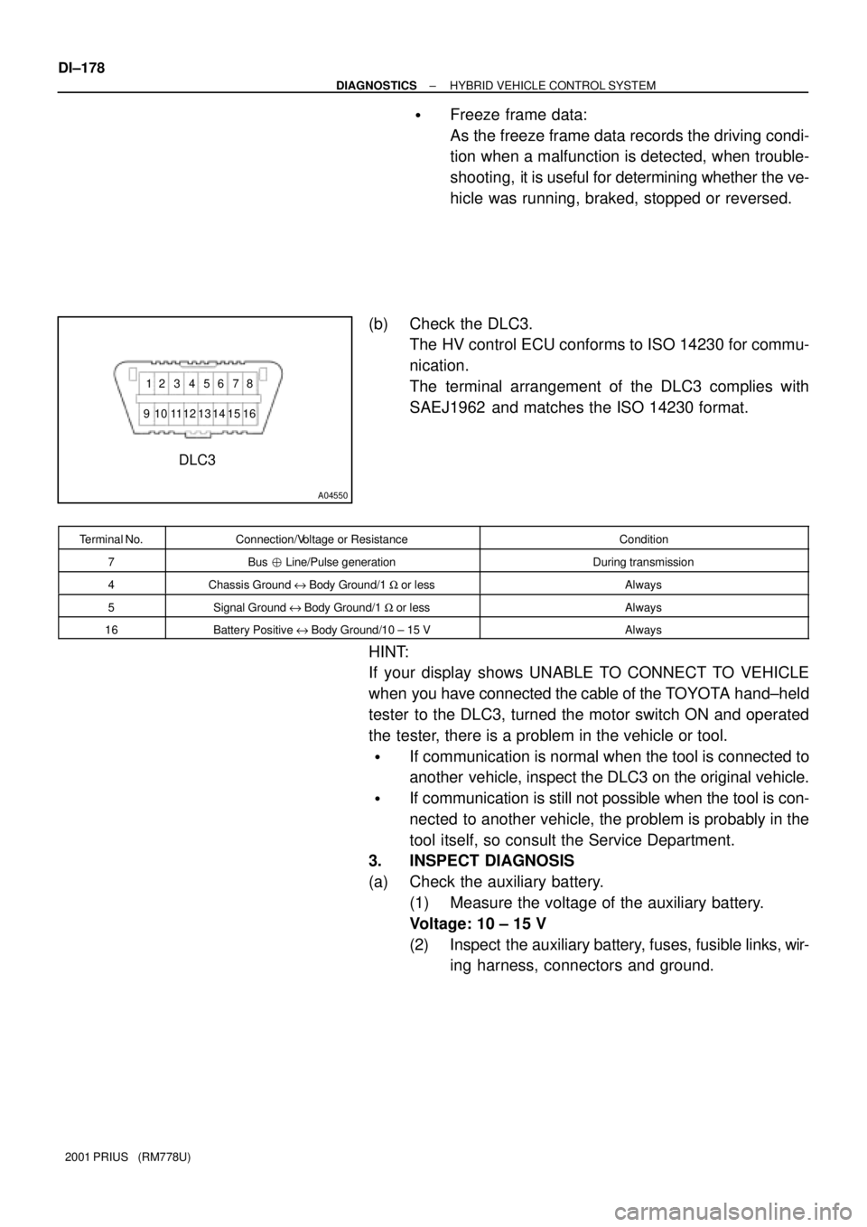
A04550
DLC3
912 3 4 56 78
16 15 14 13 12 11 10
DI±178
± DIAGNOSTICSHYBRID VEHICLE CONTROL SYSTEM
2001 PRIUS (RM778U)
�Freeze frame data:
As the freeze frame data records the driving condi-
tion when a malfunction is detected, when trouble-
shooting, it is useful for determining whether the ve-
hicle was running, braked, stopped or reversed.
(b) Check the DLC3.
The HV control ECU conforms to ISO 14230 for commu-
nication.
The terminal arrangement of the DLC3 complies with
SAEJ1962 and matches the ISO 14230 format.
Terminal No.Connection/Voltage or ResistanceCondition
7Bus � Line/Pulse generationDuring transmission
4Chassis Ground e Body Ground/1 W or lessAlways
5Signal Ground e Body Ground/1 W or lessAlways
16Battery Positive e Body Ground/10 ± 15 VAlways
HINT:
If your display shows UNABLE TO CONNECT TO VEHICLE
when you have connected the cable of the TOYOTA hand±held
tester to the DLC3, turned the motor switch ON and operated
the tester, there is a problem in the vehicle or tool.
�If communication is normal when the tool is connected to
another vehicle, inspect the DLC3 on the original vehicle.
�If communication is still not possible when the tool is con-
nected to another vehicle, the problem is probably in the
tool itself, so consult the Service Department.
3. INSPECT DIAGNOSIS
(a) Check the auxiliary battery.
(1) Measure the voltage of the auxiliary battery.
Voltage: 10 ± 15 V
(2) Inspect the auxiliary battery, fuses, fusible links, wir-
ing harness, connectors and ground.
Page 790 of 1943

± DIAGNOSTICSHYBRID VEHICLE CONTROL SYSTEM
DI±193
2001 PRIUS (RM778U)
5. CHECK FOR INTERMITTENT PROBLEMS
(a) Perform a simulation test (See page IN±41).
In the simulation test, reproduce the driving condition at the trouble occurrence according to the cus-
tomer 's comments and freeze frame data recorded with DTC, such as an opening angle of the acceler-
ator pedal, SOC, engine coolant temperature, engine rpm, and MG/1MG2 rpm and torque.
(b) Check the connector and terminal (See page IN±41).
(c) Handle the connector (See page IN±41).
6. TOYOTA HAND±HELD TESTER DISPLAY ITEMS
TOYOTA Hand±held tester displayMeasurement Item
1 BEF LATST ORNumber of operation of 1 trip before last
1 BEF LATST TRPNumber of trips before last
2 BEF LATST ORNumber of operation 2 trips before last
2 BEF LATST TRPNumber of trips 2 before last
ABNML CON BR±HVCommunication malfunction between HV ECU and brake
ACC SENSOR MAINMain accelerator sensor
ACC SENSOR SUBSub accelerator sensor
ACC TENT TRBLETentative trouble of accelerator
ACC THROTTLEAccelerator throttle
ACCEL MODEHistory of acceleration and reduction
AIR CON REQUESTAir conditioner request
AUX. BATT LOWAuxiliary battery becomes week
AUX. BATT VVoltage of auxiliary battery
BATT HIGH TEMPTemperature of the battery is too high
BATT HIGH VOLTVoltage of the battery is too high
BATT LOW BOLTVoltage of the battery is low
BATT OVER LOADBattery is overloaded
BATT SAVE RQSTRequest to save the main battery
BATTERY FULLBattery full
BRAKE TORQBrake torque
CELL TEMP±MAXHighest temperature of all battery cells
CELL TEMP±MINLowest temperature of all battery cells
CHG RESTRICTIONCharge restriction
COOLANT TEMPWater temperature
CRUISE CONTROLCondition of the cruise control
DC/DC CONV STOPDC/DC converter stop signal
DC/DC CONV STOPFactors causing DC/DC converter to stop
DC/DC STOP FACTDC/DC converter has stopped at least once
DC/DC V UNSETDC/DC voltage is unsettled
DCHG RQST SOCDischarge request to adjust SOC
DISCHAG INHIBITBattery is inhibited to discharge
Page 857 of 1943
A14140
C4
ConverterHybrid Vehicle
Control ECU
NODD
4L ± O
NODD 4
H12 DI±266
± DIAGNOSTICSHYBRID VEHICLE CONTROL SYSTEM
2001 PRIUS (RM778U)
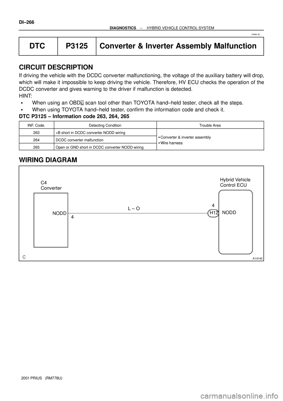
DTC P3125 Converter & Inverter Assembly Malfunction
CIRCUIT DESCRIPTION
If driving the vehicle with the DCDC converter malfunctioning, the voltage of the auxiliary battery will drop,
which will make it impossible to keep driving the vehicle. Therefore, HV ECU checks the operation of the
DCDC converter and gives warning to the driver if malfunction is detected.
HINT:
�When using an OBD scan tool other than TOYOTA hand±held tester, check all the steps.
�When using TOYOTA hand±held tester, confirm the information code and check it.
DTC P3125 ± Information code 263, 264, 265
INF. Code.Detecting ConditionTrouble Area
263+B short in DCDC converter NODD wiring
264DCDC converter malfunction�Converter & inverter assembly
�Wire harness265Open or GND short in DCDC converter NODD wiring�Wire harness
WIRING DIAGRAM
DI838±02