Page 1515 of 1943

INSTALLATION
1. INSTALL FLYWHEEL
(a) Apply adhesive to 2 or")
EM1J2±02
P08755
A13917
SSTSST
1
2
3
4
6
5
A13940
SST
A13917
SSTSST
1
2
3
4
6
5
EM±58
± ENGINE MECHANICALENGINE UNIT
2001 PRIUS (RM778U)
INSTALLATION
1. INSTALL FLYWHEEL
(a) Apply adhesive to 2 or 3 threads of the bolt end.
Adhesive: Part No. 08833±00070, THREE BOND 1324
or equivalent
(b) Install and uniformly tighten the new 6 bolts in several
passes, in the sequence shown.
Torque: 84 N´m (857 kgf´cm, 62 ft´lbf)
(c) Retighten the flywheel bolts by 90° in the numerical order
shown.
2. INSTALL DAMPER DISC
(a) Insert SST in the damper disc, then insert them in the fly-
wheel.
SST 09301±00110
HINT:
Take care not to insert damper disc in the wrong direction.
(b) Set the damper spring on the damper disc.
(c) Following the procedures shown in the illustration, tighten
the 6 bolts in the order starting the bolt locating near the
knock pin on the top.
Torque: 16 N´m (163 kgf´cm, 12 ft´lbf)
HINT:
�Following the order in the illustration, tighten the bolts at
a time evenly.
�Move SST up and down, right and left lightly, after check-
ing that the disc in the center, tighten the bolts.
3. INSTALL TRANSAXLE TO ENGINE
(a) Attach the transaxle to the engine, and install the 6 bolts.
Torque: 33 N´m (337 kgf´cm, 24 ft´lbf)
(b) Install the dust cover.
(c) Install the LH engine mounting bracket.
Torque: 52 N´m (530 kgf´cm, 38 ft´lbf)
Page 1516 of 1943

4. SET ENGINE JACK
NOTICE:
Using a chain, hold the engine tightly.
5. INSTALL ENGINE AND TRANSAXL")
A13913
A13914
A13912
AB
B
A
A13911
A13910
± ENGINE MECHANICALENGINE UNIT
EM±59
2001 PRIUS (RM778U)
4. SET ENGINE JACK
NOTICE:
Using a chain, hold the engine tightly.
5. INSTALL ENGINE AND TRANSAXLE ASSEMBLY IN
VEHICLE
(a) Raise the engine into the engine compartment.
(b) Keep the engine level, and align RH and LH mountings
with the insulator.
(c) Connect the LH mounting bracket to the insulator with the
nut.
Torque: 80 N´m (816 kgf´cm, 59 ft´lbf)
(d) Connect the RH mounting bracket to the insulator with the
2 bolts and 2 nuts.
Torque: 52 N´m (530 kgf´cm, 38 ft´lbf)
6. INSTALL SUSPENSION MEMBER
Connect the suspension member with the 4 bolts.
Torque:
Bolt A: 113 N´m (1,152 kgf´cm, 83 ft´lbf)
Bolt B: 157 N´m (1,601 kgf´cm, 116 ft´lbf)
7. INSTALL TORQUE ROD
(a) Install the torque rod through bolt and nut.
Torque: 100 N´m (1,020 kgf´cm, 74 ft´lbf)
(b) Install the 2 bolts.
Torque: 60 N´m (612 kgf´cm, 44 ft´lbf)
8. INSTALL DRIVE SHAFTS (See page SA±23)
9. CONNECT BALL JOINT TO LOWER ARM
Torque: 142 N´m (1,448 kgf´cm, 105 ft´lbf)
10. CONNECT STABILIZER BAR LINK
Torque: 74 N´m (755 kgf´cm, 55 ft´lbf)
11. CONNECT TIE ROD END TO STEERING KNUCKLE
(See page SA±14)
Page 1517 of 1943

12. INSTALL EXHAUST PIPE
(a) Install the 2 gaskets to the exhaust pipe and connect the
2 O±rings.
(b) Install")
A13939
I18009
A13909
A13938
EM±60
± ENGINE MECHANICALENGINE UNIT
2001 PRIUS (RM778U)
12. INSTALL EXHAUST PIPE
(a) Install the 2 gaskets to the exhaust pipe and connect the
2 O±rings.
(b) Install the 2 springs and 3 bolts.
Torque:
Front exhaust pipe: 62 N´m (630 kgf´cm, 46 ft´lbf)
Tailpipe: 32 N´m (326 kgf´cm, 24 ft´lbf)
(c) Connect the hose to the actuator.
(d) Connect the heated oxygen sensor.
13. INSTALL A/C COMPRESSER
(a) Connect the A/C compresser to the engine with the 4
bolts.
Torque: 25 N´m (255 kgf´cm, 18 ft´lbf)
(b) Connect the A/C compresser connector.
14. CONNECT INTERMEDIATE EXTENSION STEERING
ASSEMBLY (See page SR±14)
15. INSTALL DRIVE BELT (See page SA±23)
16. CONNECT FUEL TUBE
17. INSTALL J/B NO. 1 TO RH FENDER APRON
18. CONNECT ENGINE WIRE TO CABIN
(a) Pull in the engine wire to the cowk panel and connect the
grommet.
(b) Connect the ECM connectors.
(c) Install the ECM (See page SF±63).
19. INSTALL BRAKE RESERVOIR TANK
(a) Install the reservoir tank with the 2 bolts.
(b) Connect the brake fluid level sensor connector.
20. CONNECT SHIFT LEVER CABLE TO TRANSAXLE
21. CONNECT HEATER HOSE TO CYLINDER BLOCK
22. CONNECT 2 RADIATOR HOSES TO RADIATOR
23. INSTALL ENGINE COOLANT RESERVOIR TANK
24. INSTALL AIR INLET
Page 1519 of 1943
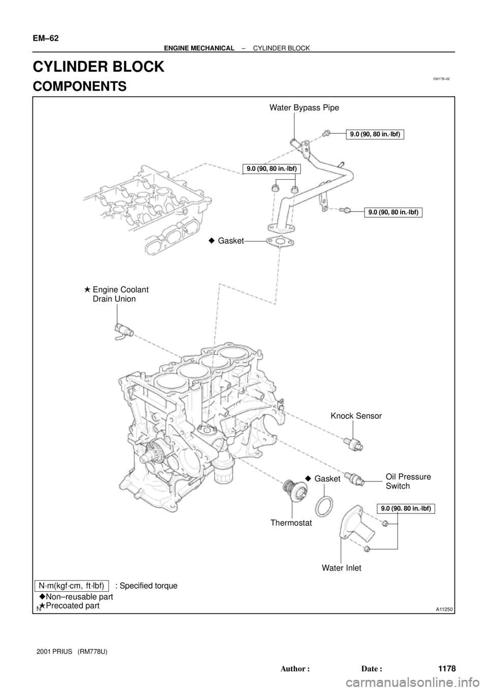
EM17B±02
A11250
Water Bypass Pipe
Knock Sensor
Thermostat
Water Inlet Engine Coolant
Drain Union
�
N´m(kgf´cm, ft´lbf) : Specified torque
�Non±reusable part
�Precoated part
Gasket
�
�GasketOil Pressure
Switch
9.0 (90, 80 in.´lbf)
9.0 (90, 80 in.´lbf)
9.0 (90. 80 in.´lbf)
9.0 (90, 80 in.´lbf)
EM±62
± ENGINE MECHANICALCYLINDER BLOCK
1178 Author�: Date�:
2001 PRIUS (RM778U)
CYLINDER BLOCK
COMPONENTS
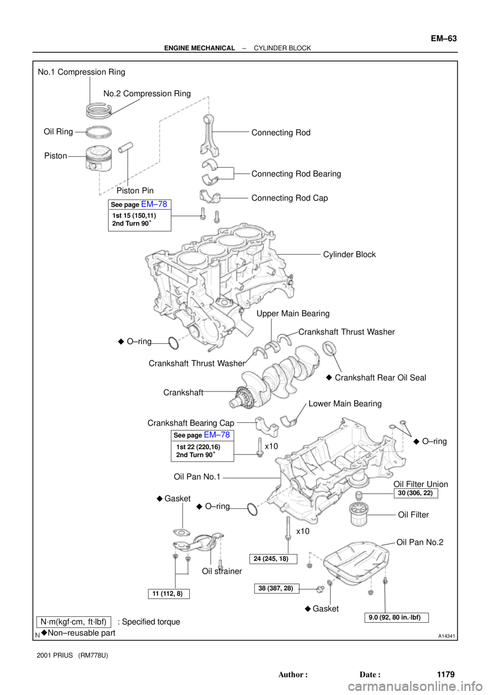
Page 1520 of 1943
A14341
No.1 Compression Ring
No.2 Compression Ring
Oil Ring
PistonConnecting Rod
Connecting Rod Bearing
� Crankshaft Rear Oil Seal
Lower Main Bearing Connecting Rod Cap
Cylinder Block
Upper Main Bearing
Crankshaft Thrust Washer
Crankshaft
Crankshaft Bearing Cap
GasketCrankshaft Thrust Washer
Oil Filter Union
Oil Filter
Oil Pan No.2
Oil strainer
11 (112, 8)38 (387, 28)
Piston Pin
30 (306, 22)
24 (245, 18)
N´m(kgf´cm, ft´lbf) : Specified torque
�Non±reusable part
See page EM±78
x10
x10
O±ring
�
�
Gasket
�O±ring
�
See page EM±78
1st 22 (220,16)
2nd Turn 90° 1st 15 (150,11)
2nd Turn 90°O±ring
�
Oil Pan No.1
9.0 (92, 80 in.´lbf)
± ENGINE MECHANICALCYLINDER BLOCK
EM±63
1179 Author�: Date�:
2001 PRIUS (RM778U)
Page 1523 of 1943

(f) Lay a strip of Plastigage the crank pin.
(g) Install the connec")
A10455
Plastigage
A10456
A10457
A01198
Mark
1, 2 or 3
Mark
1, 2 or 3
EM±66
± ENGINE MECHANICALCYLINDER BLOCK
2001 PRIUS (RM778U)
(f) Lay a strip of Plastigage the crank pin.
(g) Install the connecting rod cap with the 2 bolts.
(See page EM±78)
Torque:
1ST 15 N´m (150 kgf´cm, 11 ft´lbf)
2ND Turn 90 °
NOTICE:
Do not turn the crankshaft.
(h) Remove the 2 bolts, connecting rod cap and lower bear-
ing. (See procedure (b) and (c) above)
(i) Measure the Plastigage at its widest point.
Standard oil clearance:
0.016 ± 0.040 mm (0.0006 ± 0.0016 in.)
Maximum oil clearance:
0.06 mm (0.0024 in.)
If the oil clearance is greater than maximum, replace the bear-
ings. If necessary, grind or replace the crankshaft.
HINT:
If replacing a bearing, replace it with one having the same num-
ber as marked on the connecting rod. There are 3 sizes of stan-
dard bearings, marked º1º, º2º and º3º accordingly.
Reference
Standard bearing center wall thickness
Markmm (in.)
º1º1.488 ± 1.492 (0.0586 ± 0.0587)
º2º1.492 ± 1.496 (0.0587 ± 0.0589)
º3º1.496 ± 1.500 (0.0589 ± 0.0591)
(j) Completely remove the plastigage.
Page 1525 of 1943

+
Crankshaft (B)
Use bearing0 ± 2 3 ± 5")
A10461
A10462
A10463
No. 1No. 2
No. 3
No. 4No. 5
No. 5
No. 4
No. 3
No. 2
No. 1
Number
Mark
Total number º º: Number mark
Cylinder block (A)
+
Crankshaft (B)
Use bearing0 ± 2 3 ± 5 6 ± 8 9 ±11
º1º
EXAMPLE: Cylinder block º4º (A)
+ Crankshaft º3º (B)
= Total number 7 (Use bearing º3º)º2º º3º º4º EM±68
± ENGINE MECHANICALCYLINDER BLOCK
2001 PRIUS (RM778U)
(e) Check each main journal and bearing for pitting and
scratches.
If the journal or bearing is damaged, replace the bearing.
If necessary, grind or replace the crankshaft.
(f) Place the crankshaft on the cylinder block.
(g) Lay a strip of plastigage acrose each journal.
(h) Install the bearing caps (See page EM±45).
Torque:
1ST 22 N´m (220 kgf´cm, 16 ft´lbf)
2ND Turn 90 °
NOTICE:
Do not turn the crankshaft.
(i) Remove the bearing caps (See procedure (a) and (b)
above).
(j) Measure the plastigage at its widest point.
Standard oil clearance:
0.010 ± 0.023 mm (0.0004 ± 0.0009 in.)
Maximum oil clearance:
0.07 mm (0.0028 in.)
If the oil clearance is greater then maximum, replace the bear-
ings. If necessary, replace the crankshaft.
HINT:
If using a standard bearing, replace it with one having the same
number. If the number of the bearing cannot be determined, se-
lect the correct bearing by adding together the numbers im-
printed on the cylinder block and crankshaft, then selecting the
bearing with the same number as the total. There are 4 sizes
of standard bearings, marked º1º, º2º, º3º and º4º accordingly.
Page 1536 of 1943

(c) Install and uniformly tighten the 10 bolts of the bearing
cap is several passes, in the sequence shown.
Torque:
1ST 22")
A01205
A10456
EM±80
± ENGINE MECHANICALCYLINDER BLOCK
2001 PRIUS (RM778U)
(c) Install and uniformly tighten the 10 bolts of the bearing
cap is several passes, in the sequence shown.
Torque:
1ST 22 N´m (220 kgf´cm, 16 ft´lbf)
2ND Turn 90 °
(d) Check that the crankshaft turns smoothly.
7. CHECK CRANKSHAFT THRUST CLEARANCE
(See page EM±64)
8. INSTALL PISTON AND CONNECTING ROD
ASSEMBLES
Using a piston ring compressor, push the correctly numbered
piston and connecting rod assemblies into each cylinder with
the front mark of the piston facing forward.
9. PLACE CONNECTING ROD CAP ON CONNECTING
ROD
(a) Match the numbered connecting rod cap with the con-
necting rod.
(b) Align the pin dowels of the connecting rod cap with the
pins of the connecting rod, and install the connecting rod.
(c) Check that the protrusion of the connecting rod cap is fac-
ing in the correct direction.
10. INSTALL CONNECTING ROD CAP BOLTS
HINT:
�The connecting rod cap bolts are tightened in 2 progres-
sive steps (steps (b) and (d)).
�If any of the connecting rod cap bolts is broken or de-
formed, replace it.
(a) Apply a light coat of engine oil on the threads and under
the heads of the connecting rod cap bolts.
(b) Install and alternately tighten the 2 connecting rod cap
bolts in several passes.
Torque:
1ST 15 N´m (150 kgf´cm, 11 ft´lbf)
2ND Turn 90 °
If any of the connecting rod cap bolts does not meet the torque
specification, replace the connecting rod cap bolts.
11. CHECK CONNECTING ROD THRUST CLEARANCE
(See page EM±64)