Page 1475 of 1943
A13926
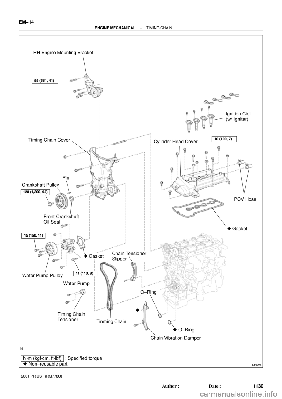
N´m (kgf´cm, ft´lbf)
� Non±reusable part: Specified torque RH Engine Mounting Bracket
Timing Chain Cover
Cylinder Head CoverIgnition Ciol
(w/ Igniter)
PCV Hose
Front Crankshaft
Oil Seal Crankshaft Pulley
Gasket
Water Pump Pulley
Water Pump
GasketChain Tensioner
Slipper
Chain Vibration Damper Tinming Chain
Timing Chain
TensionerPin
�
�
O±Ring
�
O±Ring �
11 (110, 8)
15 (150, 11)
128 (1,300, 94)
55 (561, 41)
10 (100, 7)
EM±14
± ENGINE MECHANICALTIMING CHAIN
1130 Author�: Date�:
2001 PRIUS (RM778U)
Page 1480 of 1943

INSTALLATION
1. INSTALL TIMING CHAIN
(a) After setting th")
EM1IV±02
A11224
ATDC20°Mark Link
Timing Mark
30°
Timing Mark
Mark Link
A11225
± ENGINE MECHANICALTIMING CHAIN
EM±21
2001 PRIUS (RM778U)
INSTALLATION
1. INSTALL TIMING CHAIN
(a) After setting the crankshaft at ATDC40±140 °, set cams
of intake and exhaust timing sprockets at ATDC 20 ° and
then the reset the crankshaft at ATDC 20 °.
(b) Install the chain vibration damper with the 2 bolts.
Torque: 9.0 N´m (92 kgf´cm, 80 in.´lbf)
(c) Align the match marks of timing chain mark plate (Yellow),
camshaft timing sprocket, camshaft timing gear and
crankshaft timing sprocket to install the timing chain as
shown in the illustration.
HINT:
To prevent the exhaust camshaft from spring back turn it using
a wrench and set it at the mark on a chain.
(d) Install the chain tensioner slipper.
2. INSTALL CHAIN TENSIONER
(a) While rotating the lock plate of the tensioner up±ward,
push in the plunger of the tensioner as shown in the il-
lustration.
(b) While rotating the lock plate of the tensioner down±ward,
insert a bar of 2.5 mm (0.098 in.) into the holes in the lock
plate.
(c) Install the chain tensioner with the 2 bolts.
Torque: 9.0 N´m (92 kgf´cm, 80 in.´lbf)
(d) Remove the bar from the chain tensioner.
(e) Check that the tension between the intake and exhaust
camshaft timing sprocket.
Page 1482 of 1943

(e) Install the timing chain cover, new O±ring and water pump
with the 16 bolts and 3 nuts. Uni")
A11274
A B
CE D
F
AG
G
EB
A
AA
A11258
A
B
± ENGINE MECHANICALTIMING CHAIN
EM±23
2001 PRIUS (RM778U)
(e) Install the timing chain cover, new O±ring and water pump
with the 16 bolts and 3 nuts. Uniformly tighten the bolts
and nut in several passes.
Torque:
Bolt A 11 N´m (113 kgf´cm, 8 ft´lbf)
Bolt B 24 N´m (245 kgf´cm, 18 ft´lbf)
Bolt C 11 N´m (113 kgf´cm, 8 ft´lbf)
Bolt D 24 N´m (245 kgf´cm, 18 ft´lbf)
Bolt E 11 N´m (113 kgf´cm, 8 ft´lbf)
Nut F 24 N´m (245 kgf´cm, 18 ft´lbf)
Nut G 11 N´m (113 kgf´cm, 8 ft´lbf)
NOTICE:
�Pay attention not to wrap the chain and slipper over
the chain cover seal line.
�After installing the chain cover, must install the
mounting bracket and water pump within 15 minutes.
HINT:
Each bolt length in indicated in the illustration.
A 20 mm (0.787 in.)
B 30 mm (1.181 in.)
C 35 mm (1.378 in.)
D 20 mm (0.787 in.)
E 35 mm (1.378 in.)
4. INSTALL RH ENGINE MOUNTING BRACKET
(a) Apply seal packing to threads of the mounting bolt.
Seal packing:
Part No. 08826 ± 00080 or equivalent
HINT:
Do not apply seal packing to 2 or 3 threads of the bolt end.
(b) Install the mounting bracket with the 4 bolts.
Torque: 55 N´m (561 kgf´cm, 41 ft´lbf)
5. INSTALL CRANKSHAFT POSITION SENSOR
Torque:
Bolt A 7.5 N´m (76 kgf´cm, 66 in.´lbf)
Bolt B 11 N´m (113 kgf´cm, 8 ft´lbf)
6. INSTALL OIL CONTROL VALVE (See page EM±45)
Torque: 7.5 N´m (76 kgf´cm, 66 in.´lbf)
Page 1483 of 1943

7. INSTALL CRANKSHAFT PULLEY
(a) Clean the crankshaft pulle")
A11262
SST
SST
B00301
Seal
Packing
A11222
1
23
4
5
6
7
8
9
10
11
B11761
A13928
EM±24
± ENGINE MECHANICALTIMING CHAIN
2001 PRIUS (RM778U)
7. INSTALL CRANKSHAFT PULLEY
(a) Clean the crankshaft pulley inside.
(b) Install the pin to the crankshaft.
(c) Align the hole in the crank pulley with the pin position and
install the crank pulley.
(d) Using SST, install the pulley bolt.
SST 09213±70010, 09330±00021
Torque: 128 N´m (1,300 kgf´cm, 94 ft´lbf)
8. INSTALL CYLINDER HEAD COVER
(a) Remove any old packing (FIPG) material.
(b) Apply seal packing to 2 locations as shown in the illustra-
tion.
Seal packing:
Part No. 08826 ± 00080 or equivalent
(c) Install the gasket to the cylinder head cover.
HINT:
Part must be assembled within 3 minutes of application.
Otherwise the material must be remove and reapplied.
(d) Install the cylinder head cover and cable bracket with the
7 bolts, 2 seal washers and 2 nuts.
Uniformly tighten the bolts and nuts, in the several
passes, in the sequence shown.
Torque: 10 N´m (100 kgf´cm, 7 ft´lbf)
(e) Connect the 2 PCV hoses to the cylinder head cover.
9. CONNECT ENGINE WIRE TO CYLINDER HEAD COV-
ER
10. INSTALL IGNITION COILS (See page IG±7)
11. REMOVE RH ENGINE MOUNTING INSULATOR
Install the RH engine mounting insulator with the 5 bolts and 2
nuts.
12. INSTALL VSV TO RH ENGINE MOUNTING INSULA-
TOR
13. INSTALL DRIVE BELT
14. INSTALL ENGINE COOLANT RESERVOIR TANK
15. INSTALL AIR INLET
Page 1485 of 1943
EM1IW±02
A13929
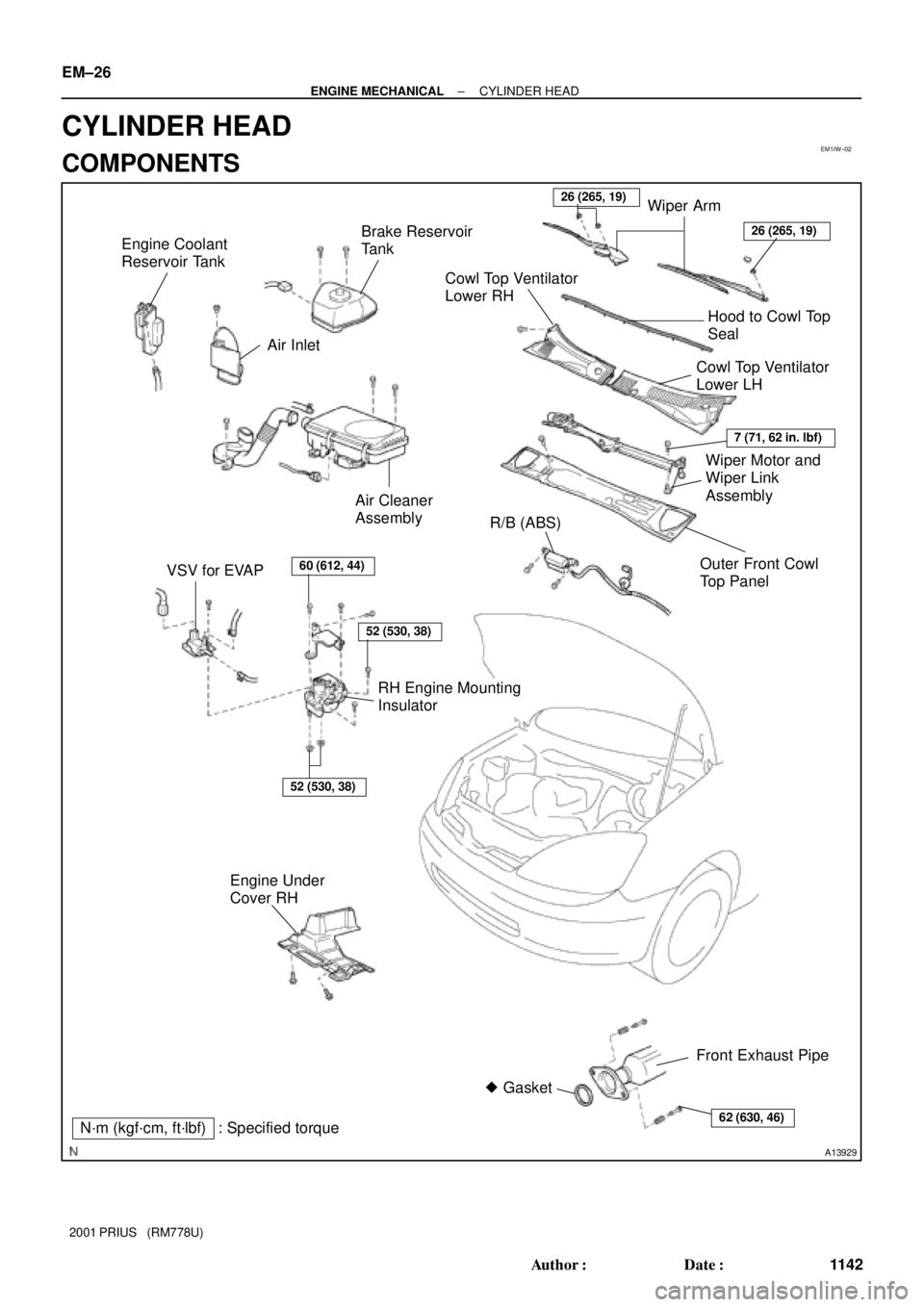
N´m (kgf´cm, ft´lbf)� Gasket
: Specified torque VSV for EVAPR/B (ABS) Air Cleaner
Assembly
RH Engine Mounting
Insulator Engine Coolant
Reservoir Tank
Engine Under
Cover RHOuter Front Cowl
Top Panel Air Inlet
60 (612, 44)
52 (530, 38)
52 (530, 38)
26 (265, 19)Brake Reservoir
Tank
Wiper Motor and
Wiper Link
Assembly
Cowl Top Ventilator
Lower LH
Cowl Top Ventilator
Lower RH
Wiper Arm
7 (71, 62 in. lbf)
26 (265, 19)
Hood to Cowl Top
Seal
62 (630, 46)
Front Exhaust Pipe
EM±26
± ENGINE MECHANICALCYLINDER HEAD
1142 Author�: Date�:
2001 PRIUS (RM778U)
CYLINDER HEAD
COMPONENTS
Page 1486 of 1943
A13930
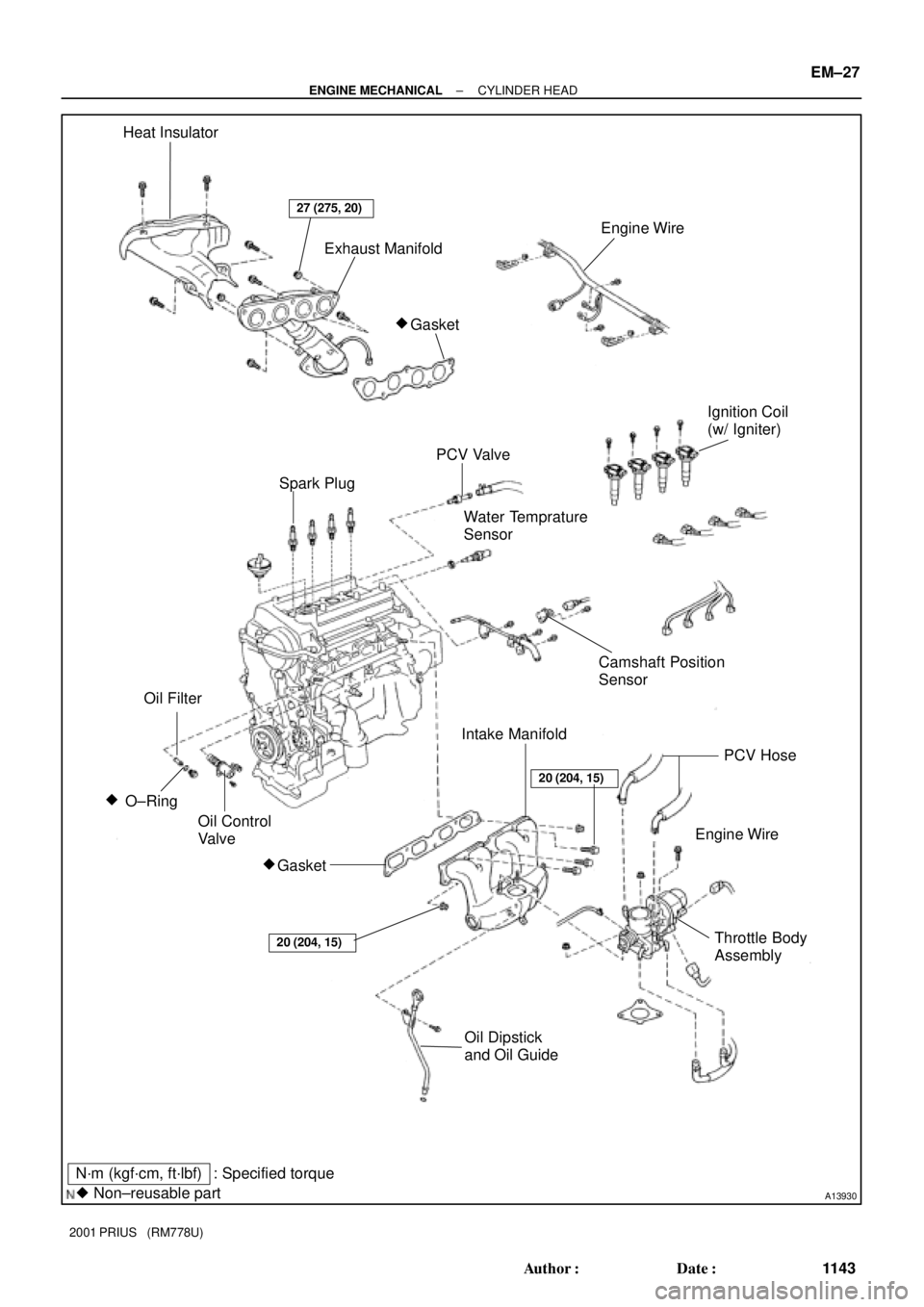
N´m (kgf´cm, ft´lbf)
� Non±reusable part: Specified torque Heat Insulator
Exhaust Manifold
Ignition Coil
(w/ Igniter)
PCV Valve
Water Temprature
Sensor
Camshaft Position
Sensor
Engine Wire
Oil Dipstick
and Oil GuideThrottle Body
Assembly O±Ring �
Gasket
�
Engine Wire
Gasket �
27 (275, 20)
Oil Filter
20 (204, 15)
PCV Hose
Oil Control
Valve
20 (204, 15)
Intake Manifold
Spark Plug
± ENGINE MECHANICALCYLINDER HEAD
EM±27
1143 Author�: Date�:
2001 PRIUS (RM778U)
Page 1487 of 1943
A13931
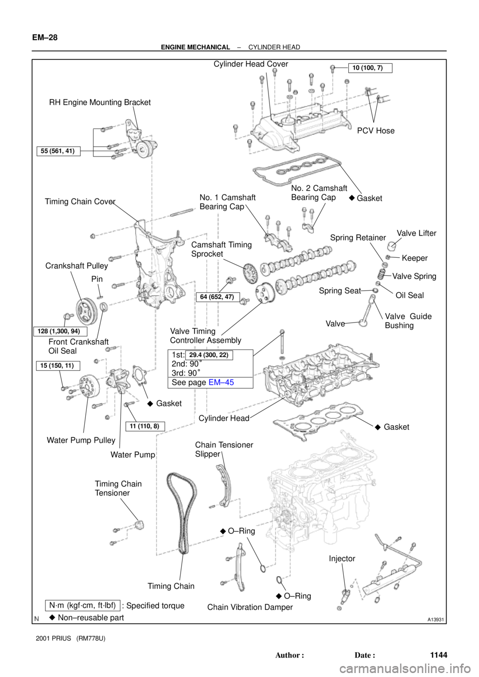
N´m (kgf´cm, ft´lbf)
� Non±reusable part: Specified torque RH Engine Mounting Bracket
Timing Chain CoverCylinder Head Cover
PCV Hose
Front Crankshaft
Oil SealGasket
Water Pump Pulley
Water Pump
O±Ring
Chain Tensioner
Slipper
Chain Vibration Damper Timing Chain
Timing Chain
Tensioner Pin
�
�
Crankshaft Pulley
Gasket
Valve Lifter
Keeper Spring Retainer
Valve Spring
Oil Seal Spring Seat
Valve Guide
Bushing
No. 1 Camshaft
Bearing Cap
Valve Timing
Controller AssemblyValve
Cylinder Head
Camshaft Timing
SprocketNo. 2 Camshaft
Bearing Cap
�
�Gasket
O±Ring
�
55 (561, 41)
128 (1,300, 94)
15 (150, 11)
11 (110, 8)
Injector
1st:
2nd: 90°
3rd: 90°
See page EM±4529.4 (300, 22)
10 (100, 7)
64 (652, 47)
EM±28
± ENGINE MECHANICALCYLINDER HEAD
1144 Author�: Date�:
2001 PRIUS (RM778U)
Page 1496 of 1943

14. INSPECT CAM LOBES
Using a micrometer, measure the cam lobe height.
Standard cam lobe he")
EM2011
EM2538
A01452
Plastigage
A12943
A01453
EM±38
± ENGINE MECHANICALCYLINDER HEAD
2001 PRIUS (RM778U)
14. INSPECT CAM LOBES
Using a micrometer, measure the cam lobe height.
Standard cam lobe height:
Intake 42.310 ± 42.410 mm (1.62637 ± 1.66968 in.)
Exhaust 44.046 ± 44.146 mm (1.73409 ± 1.73803 in.)
Minimum cam lobe height:
Intake 42.16 mm (1.6598 in.)
Exhaust 43.90 mm (1.7283 in.)
If the cam lobe height is less than minimum, replace the cam-
shaft.
15. INSPECT CAMSHAFT JOURNALS
Using a micrometer, measure the journal diameter.
No.1 journal diameter:
34.449 ± 34.465 mm (1.35626 ± 1.35689 in.)
Others journal diameter:
22.949 ± 22.965 mm (0.90350 ± 0.90413 in.)
If the journal diameter is not as specified, check the oil clear-
ance.
16. INSPECT CAMSHAFT JOURNAL CLEARANCE
(a) Clean the bearing caps and camshaft journals.
(b) Place the camshafts on the cylinder head.
(c) Lay a strip of Plastigage across each of the camshaft jour-
nal.
(d) Install the bearing caps (See page EM±45).
Torque:
No.1 23 N´m (235 kgf´cm, 17 ft´lbf)
No.2 12.7 N´m (130 kgf´cm, 10 ft´lbf)
NOTICE:
Do not turn the camshaft.
(e) Remove the bearing caps.
(f) Measure the plastigage at its widest point.
Standard oil clearance:
0.040 ± 0.095 mm (0.00157 ± 0.00374 in.)
Maximum oil clearance:
0.115 mm (0.00453 in.)
If the oil clearance is greater than maximum, replace the cam-
shaft. If necessary, replace the bearing caps and cylinder head
as a set.
(g) Completely remove the Plastigage.
(h) Remove the camshafts.