Page 1036 of 1943

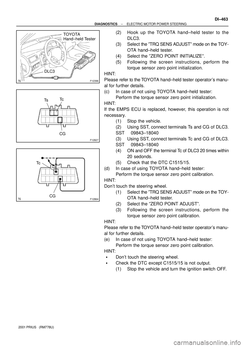
F12396
TOYOTA
Hand±held Tester
DLC3
F12827
Tc
CG
Ts
F12864
Tc
CG
± DIAGNOSTICSELECTRIC MOTOR POWER STEERING
DI±463
2001 PRIUS (RM778U)
(2) Hook up the TOYOTA hand±held tester to the
DLC3.
(3) Select the ºTRQ SENS ADJUSTº mode on the TOY-
OTA hand±held tester.
(4) Select the ºZERO POINT INITIALIZEº.
(5) Following the screen instructions, perform the
torque sensor zero point initialization.
HINT:
Please refer to the TOYOTA hand±held tester operator's manu-
al for further details.
(c) In case of not using TOYOTA hand±held tester:
Perform the torque sensor zero point initialization.
HINT:
If the EMPS ECU is replaced, however, this operation is not
necessary.
(1) Stop the vehicle.
(2) Using SST, connect terminals Ts and CG of DLC3.
SST 09843±18040
(3) Using SST, connect terminals Tc and CG of DLC3.
SST 09843±18040
(4) ON and OFF the terminal Tc of DLC3 20 times within
20 sedonds.
(5) Check that the DTC C1515/15.
(d) In case of using TOYOTA hand±held tester:
Perform the torque sensor zero point calibration.
HINT:
Don't touch the steering wheel.
(1) Select the ºTRQ SENS ADJUSTº mode on the TOY-
OTA hand±held tester.
(2) Select the ºZERO POINT ADJUSTº.
(3) Following the screen instructions, perform the
torque sensor zero point calibration.
HINT:
Please refer to the TOYOTA hand±held tester operator's manu-
al for further details.
(e) In case of not using TOYOTA hand±held tester:
Perform the torque sensor zero point calibration.
HINT:
�Don't touch the steering wheel.
�Check the DTC except C1515/15 is not output.
(1) Stop the vehicle and turn the ignition switch OFF.
Page 1038 of 1943

DI7QX±01
± DIAGNOSTICSELECTRIC MOTOR POWER STEERING
DI±465
2001 PRIUS (RM778U)
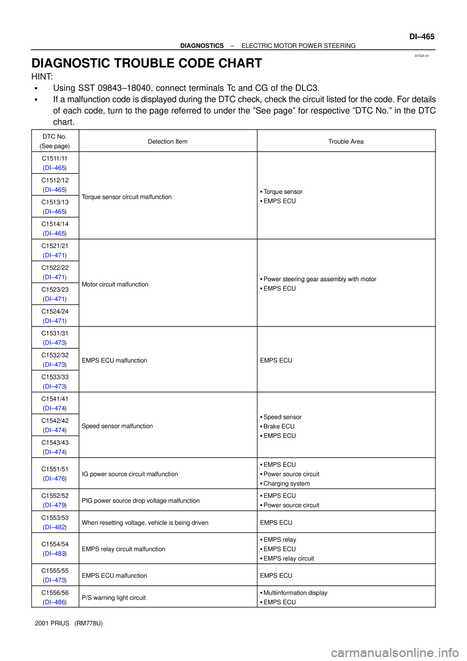
DIAGNOSTIC TROUBLE CODE CHART
HINT:
�Using SST 09843±18040, connect terminals Tc and CG of the DLC3.
�If a malfunction code is displayed during the DTC check, check the circuit listed for the code. For details
of each code, turn to the page referred to under the ºSee pageº for respective ºDTC No.º in the DTC
chart.
DTC No.
(See page)Detection ItemTrouble Area
C1511/11
(DI±465)
C1512/12
(DI±465)
T i it lf ti�Torque sensor
C1513/13
(DI±465)Torque sensor circuit malfunction�Torque sensor
�EMPS ECU
C1514/14
(DI±465)
C1521/21
(DI±471)
C1522/22
(DI±471)
Mt i it lf ti�Power steering gear assembly with motor
C1523/23
(DI±471)Motor circuit malfunction�Power steering gear assembly with motor
�EMPS ECU
C1524/24
(DI±471)
C1531/31
(DI±473)
C1532/32
(DI±473)EMPS ECU malfunctionEMPS ECU
C1533/33
(DI±473)
C1541/41
(DI±474)
C1542/42
(DI±474)Speed sensor malfunction
�Speed sensor
�Brake ECU
�EMPS ECUC1543/43
(DI±474)�EMPS ECU
C1551/51
(DI±476)IG power source circuit malfunction
�EMPS ECU
�Power source circuit
�Charging system
C1552/52
(DI±479)PIG power source drop voltage malfunction�EMPS ECU
�Power source circuit
C1553/53
(DI±482)When resetting voltage, vehicle is being drivenEMPS ECU
C1554/54
(DI±483)EMPS relay circuit malfunction
�EMPS relay
�EMPS ECU
�EMPS relay circuit
C1555/55
(DI±473)EMPS ECU malfunctionEMPS ECU
C1556/56
(DI±486)P/S warning light circuit�Multiinformation display
�EMPS ECU
Page 1040 of 1943
DI7R1±01
F12832
I01
E3
E3
E3
E31
4
2
3EMPS ECU
TRQV
TRQ1
TRQ2
TRQG (Shielded)
W
R
G
B 1 2
3
4 VCC
VT1
VT2
GND Steering Shaft
Torque Sensor
W±B 5
J/C
J18 J19AA
W±B W±B
J17 J/C
A
IG DI±470
± DIAGNOSTICSELECTRIC MOTOR POWER STEERING
2001 PRIUS (RM778U)
CIRCUIT INSPECTION
DTC
C1511/11±C1514/14Torque Sensor Circuit Malfunction
CIRCUIT DESCRIPTION
Steering torque is detected from output current of torque sensor.
DTC No.Detection ItemTrouble Area
C1511/11
C1512/12Torque sensor malfunction�Power steering gear assembly with motor
C1513/13
Torque sensor malfunction�Power steering gear assembly with motor
�EMPS ECU
C1514/14Open or short torque sensor circuit
WIRING DIAGRAM
Page 1041 of 1943
F12270
ON
TRQV
TRQG
F12271
VT1
VT2
GND
± DIAGNOSTICSELECTRIC MOTOR POWER STEERING
DI±471
2001 PRIUS (RM778U)
INSPECTION PROCEDURE
1 Check voltage between terminals TRQV and TRQG of EMPS ECU.
PREPARATION:
Remove the EMPS ECU with connectors still connected.
CHECK:
Measure the voltage between terminals TRQV and TRQG of
EMPS ECU connector.
OK:
Voltage: 4.5 ± 5.5 V
NG Check and replace the EMPS ECU.
OK
2 Check for open and short circuit in harness and connector between terminals
TRQV and TRQG of EMPS ECU connector (See page IN±41).
NG Repair and replace harness or connector.
OK
3 Check voltage between terminals VT1 and GND, VT2 and GND of torque sensor
connector.
PREPARATION:
Remove the torque sensor with connectors still connected.
CHECK:
Measure the voltage between terminals VT1 and GND, VT2 and
GND of torque sensor connector.
OK:
Steering PositionVT1VT2
Center position2.1 ± 2.9 V2.1 ± 2.9 V
Right turned0.15 ± 2.9 V2.1 ± 4.85 V
Left turned2.1 ± 4.85 V0.15 ± 2.9 V
Page 1042 of 1943
DI±472
± DIAGNOSTICSELECTRIC MOTOR POWER STEERING
2001 PRIUS (RM778U)
NG Check and replace power steering gear assem-
bly with motor (See page SR±17).
OK
4 Check for open and short circuit in harness and connector between terminals
VT
1 of torque sensor connector and TRQ1 of EMPS ECU connector, VT2 of torque
sensor connector and TRQ
2 of EMPS ECU connector (See page IN±41).
NG Repair and replace harness or connector.
OK
Check and replace EMPS ECU.
Page 1043 of 1943
DI±474
± DIAGNOSTICSELECTRIC MOTOR POWER STEERING
2001 PRIUS (RM778U)
DTC C1516/16 Calibration of Torque Sensor Zero Point Not
Completed
CIRCUIT DESCRIPTION
This DTC does not indicated trouble. This is detected when the torque sensor zero point calibration is not
completed normally.
DTC No.DTC Detecting ConditionTrouble Area
C1516/16This is detected when the torque sensor zero point calibra-
tion is not completed normally.±
INSPECTION PROCEDURE
1 Perform calibration of torque sensor zero point (See page DI±454).
2 Is DTC C1516/16 output?
Check DTC on page DI±460.
NO No problem.
YES
3 Is DTC C1532/32 output?
YES Check and replace EMPS ECU.
NO
4 Perform calibration of torque sensor zero point again (See page DI±454).
DI7R3±01
Page 1473 of 1943

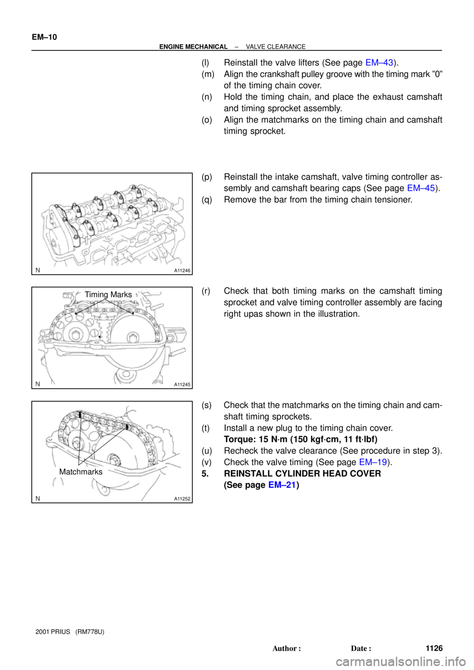
A11246
A11245
Timing Marks
A11252
Matchmarks
EM±10
± ENGINE MECHANICALVALVE CLEARANCE
1126 Author�: Date�:
2001 PRIUS (RM778U)
(l) Reinstall the valve lifters (See page EM±43).
(m) Align the crankshaft pulley groove with the timing mark º0º
of the timing chain cover.
(n) Hold the timing chain, and place the exhaust camshaft
and timing sprocket assembly.
(o) Align the matchmarks on the timing chain and camshaft
timing sprocket.
(p) Reinstall the intake camshaft, valve timing controller as-
sembly and camshaft bearing caps (See page EM±45).
(q) Remove the bar from the timing chain tensioner.
(r) Check that both timing marks on the camshaft timing
sprocket and valve timing controller assembly are facing
right upas shown in the illustration.
(s) Check that the matchmarks on the timing chain and cam-
shaft timing sprockets.
(t) Install a new plug to the timing chain cover.
Torque: 15 N´m (150 kgf´cm, 11 ft´lbf)
(u) Recheck the valve clearance (See procedure in step 3).
(v) Check the valve timing (See page EM±19).
5. REINSTALL CYLINDER HEAD COVER
(See page EM±21)
Page 1474 of 1943
EM173±04
A13942
Hood to Cowl Top
seal
VSV for EVAPR/B (ABS) Air Cleaner
Assembly
RH Engine Mounting
Insulator Engine Coolant
Reservoir Tank
Engine Under
Cover RH
N´m (kgf´cm, ft´lbf) : Specified torqueOuter Front Cowl
Top Panel Air Inlet
60 (612, 44)
52 (530, 38)
52 (530, 38)
26 (265, 19)Brake Reservoir
Tank
Wiper Motor and
Wiper Link
Assembly
Cowl Top Ventilator
Lower LH
Cowl Top Ventilator
Lower RH
Wiper Arm
7 (71, 62 in. lbf)
26 (265, 19)
± ENGINE MECHANICALTIMING CHAIN
EM±13
1129 Author�: Date�:
2001 PRIUS (RM778U)
TIMING CHAIN
COMPONENTS