Page 1476 of 1943

REMOVAL
1. DISCONNECT BATTERY NEGATIVE (±) TERMINAL
AND HV BATTERY SERVICE PLUG
(See page HV±1)
2")
EM1IU±03
A13907
A13908
A13934
A13943
± ENGINE MECHANICALTIMING CHAIN
EM±15
2001 PRIUS (RM778U)
REMOVAL
1. DISCONNECT BATTERY NEGATIVE (±) TERMINAL
AND HV BATTERY SERVICE PLUG
(See page HV±1)
2. REMOVE OUTER FR COWL TOP PANEL ASSEMBLY
(See page BO±32)
3. REMOVE RH ENGINE UNDER COVER
4. DRAIN ENGINE COOLANT
5. REMOVE AIR CLEANER ASSEMBLY
(a) Disconnect the MAF meter connector.
(b) Disconnect the EVAP hose from the air cleaner case.
(c) Loosen the 2 hose clamps.
(d) Remove the 3 bolts and air cleaner assembly.
6. REMOVE BRAKE RESERVOIR TANK
(a) Disconnect the brake fluid level sensor connector.
(b) Remove the 2 bolts and remove the reservoir tank and
suspend it.
(c) Remove the 3 bolts and reservoir tank bracket.
7. DISCONNECT CONNECTORS
(a) Disconnect the 4 ignition connectors.
(b) Disconnect the 4 injector connectors.
(c) Disconnect the 2 VSV connectors.
(d) Disconnect the camshaft position sensor connector.
(e) Disconnect the water temperature connector.
(f) Disconnect the Camshaft timing oil control valve connec-
tor.
8. REMOVE AIR INLET
9. REMOVE ENGINE COOLANT RESERVOIR TANK
10. REMOVE VSV FROM ENGINE MOUNTING INSULA-
TOR
11. REMOVE DRIVE BELT
Page 1484 of 1943
A13934
A13907
± ENGINE MECHANICALTIMING CHAIN
EM±25
2001 PRIUS (RM778U)
16. CONNECT CONNECTORS
(a) Connect the Camshaft timing oil control valve connector.
(b) Connect the water temperature sensor connector.
(c) Connect the camshaft position sensor connector.
(d) Connect the 2 VSV connectors.
(e) Connect the 4 injector connectors.
(f) Connect the 4 ignition connectors.
17. INSTALL AIR CLEANER ASSEMBLY
(a) Install the air cleaner assembly with the 2 bolts.
(b) Tighten the 2 hose clamps.
(c) Connect the EVAP hose to the air cleaner case.
(d) Connect the MAF meter connector.
18. INSTALL BRAKE RESERVOIR TANK
19. INSTALL OUTER FR COWL TOP PANEL ASSEMBLY
(See page BO±35)
20. FILL WITH ENGINE COOLANT
21. INSTALL ENGINE UNDER COVERS
22. CONNECT BATTERY NEGATIVE (±) TERMINAL AND
HV BATTERY SERVICE PLUG (See page HV±1)
23. ROAD TEST VEHICLE
Check for abnormal noises, shock slippage, correst shift points
and smooth operation.
24. RECHECK ENGINE COOLANT AND HV TRANSAXLE
COOLANT
Page 1512 of 1943

13. DISCONNECT SHIFT LEVER CABLE
14. REMOVE BRAKE RESERVOIR TANK
(a) Disconnect the brake fluid level se")
A13908
A13938
A13909
I18009
A13932
EM±54
± ENGINE MECHANICALENGINE UNIT
2001 PRIUS (RM778U)
13. DISCONNECT SHIFT LEVER CABLE
14. REMOVE BRAKE RESERVOIR TANK
(a) Disconnect the brake fluid level sensor connector.
(b) Remove the 2 bolts and remove the reservoir tank and
suspend it.
15. DISCONNECT ENGINE WIRE FROM CABIN
(a) Remove the ECM (See page SF±63).
(b) Disconnect the grommet from the cowl panel, and pull out
the engine wire.
16. REMOVE J/B NO. 1 FROM RH FENDER APRON
17. DISCONNECT FUEL TUBE
Disconnect the fuel tube from the fuel pump.
18. REMOVE DRIVE BELT
19. REMOVE ENGINE UNDER COVERS
20. REMOVE A/C COMPRESSER
(a) Disconnect the A/C compresser connector.
(b) Remove the 4 bolts and disconnect the A/C compresser
from the engine.
HINT:
Suspend the A/C compresser securely.
21. DISCONNECT INTERMEDIATE EXTENSION FROM
STEERING ASSEMBLY (See page SR±6)
22. REMOVE EXHAUST PIPE
(a) Disconnect the heated oxygen sensor from the exhaust
pipe.
(b) Remove the 2 springs and 3 bolts.
(c) Disconnect the 2 O±rings, and remove the exhaust pipe
and 2 gaskets.
Page 1517 of 1943

12. INSTALL EXHAUST PIPE
(a) Install the 2 gaskets to the exhaust pipe and connect the
2 O±rings.
(b) Install")
A13939
I18009
A13909
A13938
EM±60
± ENGINE MECHANICALENGINE UNIT
2001 PRIUS (RM778U)
12. INSTALL EXHAUST PIPE
(a) Install the 2 gaskets to the exhaust pipe and connect the
2 O±rings.
(b) Install the 2 springs and 3 bolts.
Torque:
Front exhaust pipe: 62 N´m (630 kgf´cm, 46 ft´lbf)
Tailpipe: 32 N´m (326 kgf´cm, 24 ft´lbf)
(c) Connect the hose to the actuator.
(d) Connect the heated oxygen sensor.
13. INSTALL A/C COMPRESSER
(a) Connect the A/C compresser to the engine with the 4
bolts.
Torque: 25 N´m (255 kgf´cm, 18 ft´lbf)
(b) Connect the A/C compresser connector.
14. CONNECT INTERMEDIATE EXTENSION STEERING
ASSEMBLY (See page SR±14)
15. INSTALL DRIVE BELT (See page SA±23)
16. CONNECT FUEL TUBE
17. INSTALL J/B NO. 1 TO RH FENDER APRON
18. CONNECT ENGINE WIRE TO CABIN
(a) Pull in the engine wire to the cowk panel and connect the
grommet.
(b) Connect the ECM connectors.
(c) Install the ECM (See page SF±63).
19. INSTALL BRAKE RESERVOIR TANK
(a) Install the reservoir tank with the 2 bolts.
(b) Connect the brake fluid level sensor connector.
20. CONNECT SHIFT LEVER CABLE TO TRANSAXLE
21. CONNECT HEATER HOSE TO CYLINDER BLOCK
22. CONNECT 2 RADIATOR HOSES TO RADIATOR
23. INSTALL ENGINE COOLANT RESERVOIR TANK
24. INSTALL AIR INLET
Page 1562 of 1943
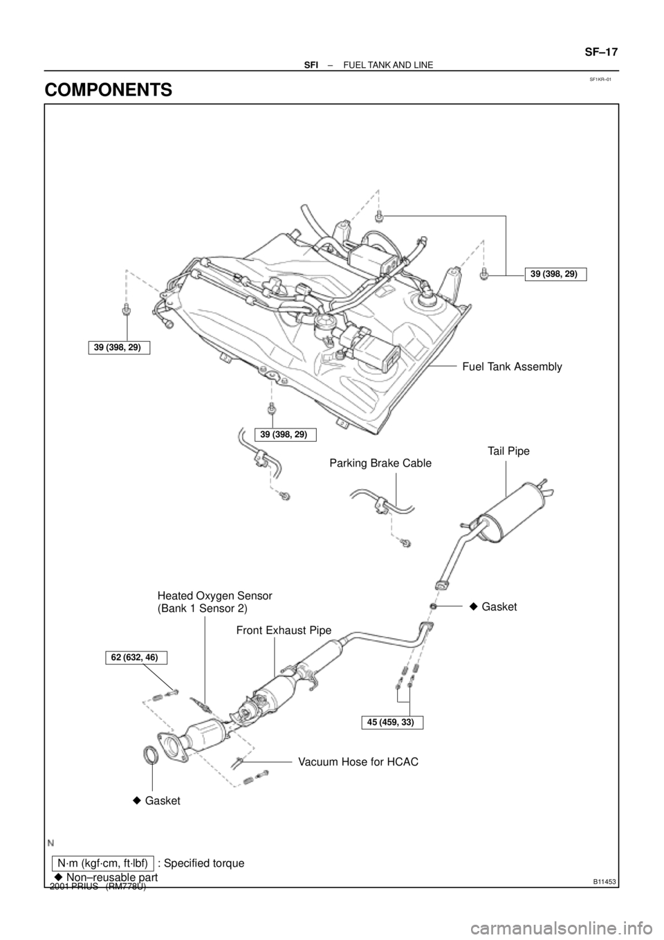
SF1KR±01
B11453
N´m (kgf´cm, ft´lbf)
� Non±reusable part: Specified torque� Gasket
Fuel Tank Assembly
Tail Pipe
39 (398, 29)
� Gasket
Front Exhaust Pipe
45 (459, 33)
39 (398, 29)
39 (398, 29)
Parking Brake Cable
62 (632, 46)
Vacuum Hose for HCAC Heated Oxygen Sensor
(Bank 1 Sensor 2)
± SFIFUEL TANK AND LINE
SF±17
2001 PRIUS (RM778U)
COMPONENTS
Page 1659 of 1943

REMOVAL
1. REMOVE FRONT WHEEL
Torque: 103 N´m (1,050 kgf´cm, 76 ft´lbf)
2. CH")
SA1ZR±01
F08617
R14731
Backlash:Deviation:
F12940SST
± SUSPENSION AND AXLEFRONT AXLE HUB
SA±9
2001 PRIUS (RM778U)
REMOVAL
1. REMOVE FRONT WHEEL
Torque: 103 N´m (1,050 kgf´cm, 76 ft´lbf)
2. CHECK BEARING BACKLASH AND AXLE HUB DEVI-
ATION
(a) Remove the 2 bolts, brake caliper and disc.
(b) Support the brake caliper securely.
(c) Using a dial indicator, check the backlash near the center
of the axle hub.
Maximum: 0.05 mm (0.0020 in.)
If the backlash exceeds the maximum, replace the bearing.
(d) Using a dial indicator, check the deviation at the surface
of the axle hub outside the hub bolt.
Maximum: 0.07 mm (0.0028 in.)
If the deviation exceeds the maximum, replace the axle hub.
(e) Install the disc, 2 bolts and brake caliper.
Torque: 107 N´m (1,090 kgf´cm, 79 ft´lbf)
3. REMOVE DRIVE SHAFT LOCK NUT
(a) Using SST and a hammer, unstake the staked part of the
lock nut.
SST 09930±00010
(b) While applying the brakes, remove the nut.
Torque: 216 N´m (2,200 kgf´cm, 159 ft´lbf)
(c) Remove the brake caliper and disc.
(d) Support the brake caliper securely.
4. REMOVE ABS SPEED SENSOR
Torque: 8.0 N´m (82 kgf´cm, 71 in.´lbf)
Page 1663 of 1943

REMOVAL
NOTICE:
�The hub bearing could be damaged if it is subjected
to the vehicle weigh")
SA20B±01
FA1535
SST
F12940SST
F11576
SST
± SUSPENSION AND AXLEFRONT DRIVE SHAFT
SA±17
2001 PRIUS (RM778U)
REMOVAL
NOTICE:
�The hub bearing could be damaged if it is subjected
to the vehicle weight, such as when moving the ve-
hicle with the drive shaft removed.
Therefore, if it is absolutely necessary to place the ve-
hicle weight on the hub bearing, first support it with
the SST.
SST 09608±16042 (09608±02021, 09608±02041)
�After disconnecting the drive shaft from the axle hub,
work carefully so as not to damage the ABS speed
sensor rotor serrations on the drive shaft.
1. REMOVE FRONT WHEEL
Torque: 103 N´m (1,050 kgf´cm, 76 ft´lbf)
2. REMOVE ENGINE UNDER COVER
3. DRAIN ATF
4. REMOVE DRIVE SHAFT LOCK NUT
(a) Using SST and a hammer, unstake the staked part of the
lock nut.
SST 09930±00010
(b) While applying the brakes, remove the nut.
Torque: 216 N´m (2,200 kgf´cm, 159 ft´lbf)
5. DISCONNECT TIE ROD END FROM STEERING
KNUCKLE
(a) Remove the cotter pin and nut.
Torque: 49 N´m (500 kgf´cm, 36 ft´lbf)
HINT:
At the time of installation, if the holes for a new cotter pin are not
aligned, tighten the nut further up to 60°.
(b) Using SST, disconnect the tie rod end from the steering
knuckle.
SST 09628±62011
Page 1673 of 1943
SA1ZU±01
F11598
SST
F11599
F11593
Wood
F11618
± SUSPENSION AND AXLEREAR SHOCK ABSORBER
SA±51
2001 PRIUS (RM778U)
REMOVAL
1. REMOVE REAR WHEELS
Torque: 103 N´m (250 kgf´cm, 18 ft´lbf)
2. REMOVE REAR SEAT (See page BO±83)
3. DISCONNECT BRAKE LINES
(a) Using SST, disconnect the brake lines from the flexible
hose. Use a container to catch brake fluid as it drains out.
SST 09751±36011
(b) Remove the clip.
(c) Employ the same manner described above to the other
side.
4. DISCONNECT ABS SPEED SENSOR WIRE HARNESS
Remove the 4 nuts, and disconnect the ABS speed sensor wire
harness from the axle beam.
Torque: 5.4 N´m (55 kgf´cm, 48 in.´lbf)
5. SUPPORT REAR AXLE BEAM AT RIGHT AND LEFT
SIDES WITH JACKS
6. REMOVE SHOCK ABSORBER
(a) Remove the 2 nuts and bolt.
Torque: 80 N´m (816 kgf´cm, 59 ft´lbf)

16. CONNECT CONNECTORS
(a) Connect the Camshaft timing oil control valve connector.
(b) Connect the water temperature sens")

REMOVAL
1. REMOVE REAR WHEELS
Torque: 103 N´m (250 kgf´cm, 18 ft´lbf)
2. REMOVE")