Page 974 of 1943

± DIAGNOSTICSANTI±LOCK BRAKE SYSTEM WITH EBD & RBS
DI±397
2001 PRIUS (RM778U)
DTCC1220±C1222/C1246/46Each Hydraulic Pressure Sensor Cir-
cuit
CIRCUIT DESCRIPTION
DTC No.DTC Detecting ConditionTrouble Area
C1220/46
Either of the following 1. or 2. is detected:
1. When the ignition switch is ON, the condition that the
voltage of the terminal PREG in brake ECU is 0.14 V or
less or 4.85 V or more, or that of terminal VREG is 4.4 V
or less or 5.6 V or more continues for 1.2 sec. or more.
2. At a vehicle speed of 15 km/h (24 mph) or more, when
both the brake switch and hydro motor are OFF, the
voltage ratio of the terminal PREG to VREG of brake
ECU is 0.06 or less or 0.14 or more continues for 8 sec.
and this condition occurs consecutively 10 times.
�Regulator (REG) pressure sensor
�Regulator (REG) pressure sensor circuit
�Brake actuator
C1221/46
Either of the following 1. or 2. is detected:
1. When the ignition switch is ON, the condition that the
voltage of the terminal PFR in brake ECU is 0.14 V or
less or 4.85 V or more, or that of terminal VFR is 4.4 V
or less or 5.6 V or more continues for 1.2 sec. or more.
2. At a vehicle speed of 15 km/h (24 mph) or more, when
both the brake switch and hydro motor are OFF, the
voltage ratio of the terminal PFR to VFR of brake ECU is
0.06 or less or 0.14 or more continues for 8 sec. and this
condition occurs consecutively 10 times.
�Front (FR) pressure sensor
�Front (FR) pressure sensor circuit
�Brake actuator
C1222/46
Either of the following 1. or 2. is detected:
1. When the ignition switch is ON, the condition that the
voltage of the terminal PRR in brake ECU is 0.14 V or
less or 4.85 V or more, or that of terminal VRR is 4.4 V
or less or 5.6 V or more continues for 1.2 sec. or more.
2. At a vehicle speed of 15 km/h (24 mph) or more, when
both the brake switch and hydro motor are OFF, the
voltage ratio of the terminal PRR to VRR of brake ECU
is 0.06 or less or 0.14 or more continues for 8 sec. and
this condition occurs consecutively 10 times.
�Rear (RR) pressure sensor
�Rear (RR) pressure sensor circuit
�Brake actuator
C1246/46
Either of the following 1. or 2. is detected:
1. When the ignition switch is ON, the condition that the
voltage of the terminal PMC in brake ECU is 0.14 V or
less or 4.85 V or more, or that of terminal VMC is 4.4 V
or less or 5.6 V or more continues for 1.2 sec. or more.
2. At a vehicle speed of 15 km/h (24 mph) or more, when
both the brake switch and hydro motor are OFF, the
voltage ratio of the terminal PMC to VMC of brake ECU
is 0.06 or less or 0.14 or more continues for 8 sec. and
this condition occurs consecutively 10 times.
�Master cylinder (M/C) pressure sensor
�Master cylinder (M/C) pressure sensor circuit
�Brake actuator
DI296±06
Page 976 of 1943
± DIAGNOSTICSANTI±LOCK BRAKE SYSTEM WITH EBD & RBS
DI±399
2001 PRIUS (RM778U)
INSPECTION PROCEDURE
HINT:
Start the inspection from step 1 in case of using the TOYOTA hand±held tester and start from step 2 in case
of not using the TOYOTA hand±held tester.
1 Check output value of the each pressure sensor.
PREPARATION:
(a) Connect the TOYOTA hand±held tester to the DLC3.
(b) Turn the ignition switch ON, and push the TOYOTA hand±held tester main switch ON.
(c) Select the DATALIST mode on the TOYOTA hand±held tester.
CHECK:
Check that the brake fluid pressure value of the master cylinder pressure sensor, regulator pressure sensor,
front pressure sensor and rear pressure sensor displayed on the TOYOTA hand±held tester is changing
when depressing the brake pedal.
OK:
Brake fluid pressure value must be changing.
OK Go to step 4.
NG
Page 977 of 1943

F12669
ON
E
2
FRR
PREG
PFR
PMC
EREGERR
EFR
DI±400
± DIAGNOSTICSANTI±LOCK BRAKE SYSTEM WITH EBD & RBS
2001 PRIUS (RM778U)
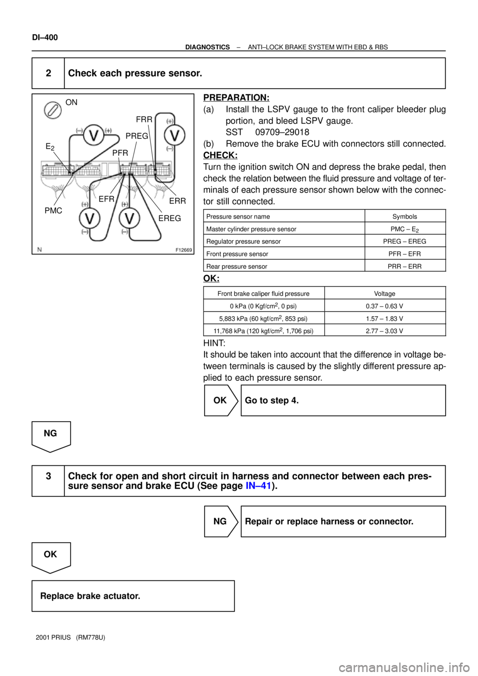
2 Check each pressure sensor.
PREPARATION:
(a) Install the LSPV gauge to the front caliper bleeder plug
portion, and bleed LSPV gauge.
SST 09709±29018
(b) Remove the brake ECU with connectors still connected.
CHECK:
Turn the ignition switch ON and depress the brake pedal, then
check the relation between the fluid pressure and voltage of ter-
minals of each pressure sensor shown below with the connec-
tor still connected.
Pressure sensor nameSymbols
Master cylinder pressure sensorPMC ± E2
Regulator pressure sensorPREG ± EREG
Front pressure sensorPFR ± EFR
Rear pressure sensorPRR ± ERR
OK:
Front brake caliper fluid pressureVoltage
0 kPa (0 Kgf/cm2, 0 psi)0.37 ± 0.63 V
5,883 kPa (60 kgf/cm2, 853 psi)1.57 ± 1.83 V
11,768 kPa (120 kgf/cm2, 1,706 psi)2.77 ± 3.03 V
HINT:
It should be taken into account that the difference in voltage be-
tween terminals is caused by the slightly different pressure ap-
plied to each pressure sensor.
OK Go to step 4.
NG
3 Check for open and short circuit in harness and connector between each pres-
sure sensor and brake ECU (See page IN±41).
NG Repair or replace harness or connector.
OK
Replace brake actuator.
Page 1030 of 1943
F12687
DLC3
2DTs 4
Ts
8
4 CG14ID1GR±G
B11
W±B
AJ11
J/C
A
ID
C Instrument Panel J/BBrake ECU
J16
J/C
J24
J/CB
W±B W±B
A2K 8 3
GR±G GR±G
B DI±454
± DIAGNOSTICSANTI±LOCK BRAKE SYSTEM WITH EBD & RBS
2001 PRIUS (RM778U)
Ts Terminal Circuit
CIRCUIT DESCRIPTION
The sensor check circuit detects abnormalities in the speed sensor signal which cannot be detected by the
DTC check.
Connecting terminals Ts and CG of the DLC3 starts the check.
WIRING DIAGRAM
DI29J±12
Page 1035 of 1943

F12396
TOYOTA
Hand±held Tester
DLC3
DI±462
± DIAGNOSTICSELECTRIC MOTOR POWER STEERING
2001 PRIUS (RM778U)
(b) In case of using TOYOTA hand±held tester:
Check the input signal.
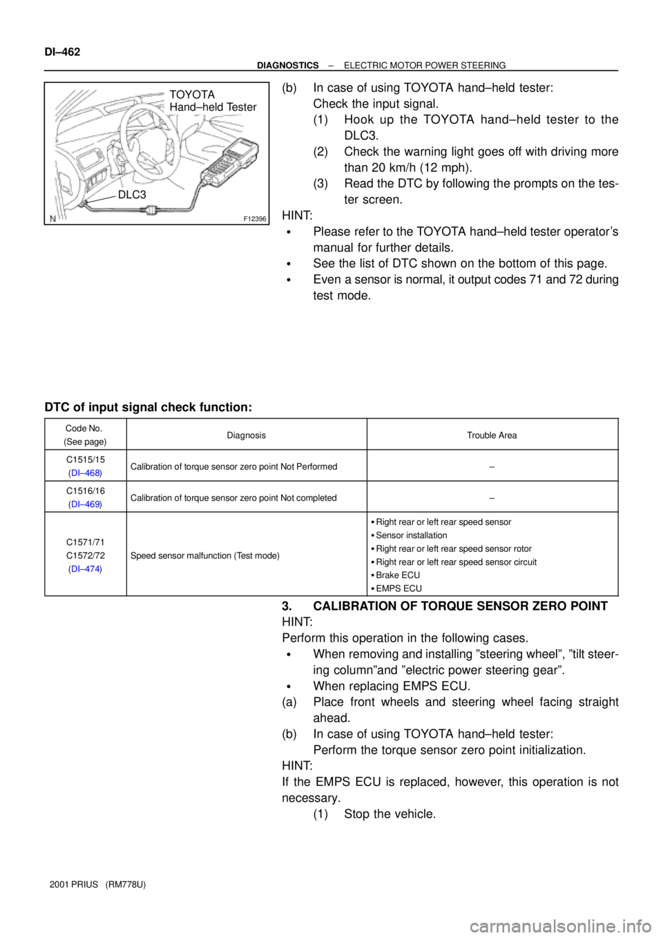
(1) Hook up the TOYOTA hand±held tester to the
DLC3.
(2) Check the warning light goes off with driving more
than 20 km/h (12 mph).
(3) Read the DTC by following the prompts on the tes-
ter screen.
HINT:
�Please refer to the TOYOTA hand±held tester operator's
manual for further details.
�See the list of DTC shown on the bottom of this page.
�Even a sensor is normal, it output codes 71 and 72 during
test mode.
DTC of input signal check function:
Code No.
(See page)DiagnosisTrouble Area
C1515/15
(DI±468)Calibration of torque sensor zero point Not Performed±
C1516/16
(DI±469)Calibration of torque sensor zero point Not completed±
C1571/71
C1572/72
(DI±474)
Speed sensor malfunction (Test mode)
�Right rear or left rear speed sensor
�Sensor installation
�Right rear or left rear speed sensor rotor
�Right rear or left rear speed sensor circuit
�Brake ECU
�EMPS ECU
3. CALIBRATION OF TORQUE SENSOR ZERO POINT
HINT:
Perform this operation in the following cases.
�When removing and installing ºsteering wheelº, ºtilt steer-
ing columnºand ºelectric power steering gearº.
�When replacing EMPS ECU.
(a) Place front wheels and steering wheel facing straight
ahead.
(b) In case of using TOYOTA hand±held tester:
Perform the torque sensor zero point initialization.
HINT:
If the EMPS ECU is replaced, however, this operation is not
necessary.
(1) Stop the vehicle.
Page 1038 of 1943

DI7QX±01
± DIAGNOSTICSELECTRIC MOTOR POWER STEERING
DI±465
2001 PRIUS (RM778U)
DIAGNOSTIC TROUBLE CODE CHART
HINT:
�Using SST 09843±18040, connect terminals Tc and CG of the DLC3.
�If a malfunction code is displayed during the DTC check, check the circuit listed for the code. For details
of each code, turn to the page referred to under the ºSee pageº for respective ºDTC No.º in the DTC
chart.
DTC No.
(See page)Detection ItemTrouble Area
C1511/11
(DI±465)
C1512/12
(DI±465)
T i it lf ti�Torque sensor
C1513/13
(DI±465)Torque sensor circuit malfunction�Torque sensor
�EMPS ECU
C1514/14
(DI±465)
C1521/21
(DI±471)
C1522/22
(DI±471)
Mt i it lf ti�Power steering gear assembly with motor
C1523/23
(DI±471)Motor circuit malfunction�Power steering gear assembly with motor
�EMPS ECU
C1524/24
(DI±471)
C1531/31
(DI±473)
C1532/32
(DI±473)EMPS ECU malfunctionEMPS ECU
C1533/33
(DI±473)
C1541/41
(DI±474)
C1542/42
(DI±474)Speed sensor malfunction
�Speed sensor
�Brake ECU
�EMPS ECUC1543/43
(DI±474)�EMPS ECU
C1551/51
(DI±476)IG power source circuit malfunction
�EMPS ECU
�Power source circuit
�Charging system
C1552/52
(DI±479)PIG power source drop voltage malfunction�EMPS ECU
�Power source circuit
C1553/53
(DI±482)When resetting voltage, vehicle is being drivenEMPS ECU
C1554/54
(DI±483)EMPS relay circuit malfunction
�EMPS relay
�EMPS ECU
�EMPS relay circuit
C1555/55
(DI±473)EMPS ECU malfunctionEMPS ECU
C1556/56
(DI±486)P/S warning light circuit�Multiinformation display
�EMPS ECU
Page 1047 of 1943
F12836
B11
E6 10
4EMPS ECU
WRL
WRR (Shielded)
W
B 15
J/C
J18 J19AA
W±B J17 J/C
A
IGE6
B1123 RLO
RRO BRAKE ECU
± DIAGNOSTICSELECTRIC MOTOR POWER STEERING
DI±479
2001 PRIUS (RM778U)
DTCC1541/41±C1543/43Speed Sensor Malfunction
DTC
C1571/71, C1572/72 Speed Sensor Malfunction (Test Mode)
CIRCUIT DESCRIPTION
DTC No.DTC Detecting ConditionTrouble Area
C1541/41�Speed sensor
C1542/42Speed sensor malfunction
�Speed sensor
�Brake ECU
C1543/43
S eed sensor malfunctionBrake ECU
�EMPS ECU
C1571/71S d lf ti (T t d )
�Right rear or left rear speed sensor
�Sensor installation
�Ri
ght rear or left rear speed sensor rotorC1571/71
C1572/72Speed sensor malfunction (Test mode)�Right rear or left rear s eed sensor rotor
�Right rear or left rear speed sensor circuit
�Brake ECU
�EMPS ECU
WIRING DIAGRAM
DI7R6±01
Page 1222 of 1943

DI7XS±01
DI±674
± DIAGNOSTICSCOMBINATION METER SYSTEM
2001 PRIUS (RM778U)
PROBLEM SYMPTOMS TABLE
TROUBLESHOOTING:
Flow chart No.SymptomSee page
1Check the communication between the combination meter and the multiplex com-
munication circuit.DI±671
2The whole meter does not functionDI±672
3The margin of error in speedometer is large. Or it remains as 0 mph.DI±673
4Fuel receiver gauge is inoperative or improper.DI±674
5Indicators or warning lights do not light up.DI±676
Fuel gauge:
SymptomSuspect AreaSee page
Displayed level is higher or lower than the actual level.1. Inclination sensor resetting
2. Body ECUBE±47
IN±41
General:
SymptomSuspect area
Meter display does not properly function.3. Combination meter ECU
Entirely black screen appears.1. Fuse
2. Wire harness and connector
3. Combination meter ECU
Turning the light control switch ON does not dim the light.1. Illumination switch
2. Wire harness and connector
3. Combination meter ECU
Brightness cannot be changed by the illumination switch operation.1. Illumination switch
2. Wire harness and connector
3. Combination meter ECU
Speedometer:
SymptomSuspect area
Improper display (Remained as 0 km/h)1. Accessory that utilizes vehicle speed signals
2. Brake ECU
3. Combination meter ECU
4. Wire harness and connector
Speedometer only does not light up.1. Combination meter ECU
Abnormal display (Incomplete numbers displayed)1. Combination meter ECU
DIsplayed value changes frequently or sharply.1. Accessory that utilizes vehicle speed signals
2. Brake ECU
3. Combination meter ECU
4. Wire harness and connector
Margin of error in speedometer is large.1. Accessory that utilizes vehicle speed signals
2. Brake ECU
3. Combination meter ECU
4. Wire harness and connector
ODO/TRIP Meter:
SymptomSuspect area
ODO/TRIP only does not light up.1. Combination meter ECU
Abnormal display (Incomplete number displayed)1. Combination meter ECU
Both meters do not integrate values. (When speedometer is normal)1. Combination meter ECU
Trip meter only does not integrate values.1. ODO/TRIP switch
2. Combination meter ECU