2001 TOYOTA PRIUS Door key lock
[x] Cancel search: Door key lockPage 8 of 1943
2001 PRIUS (EWD414U)
B HOW TO USE THIS MANUAL
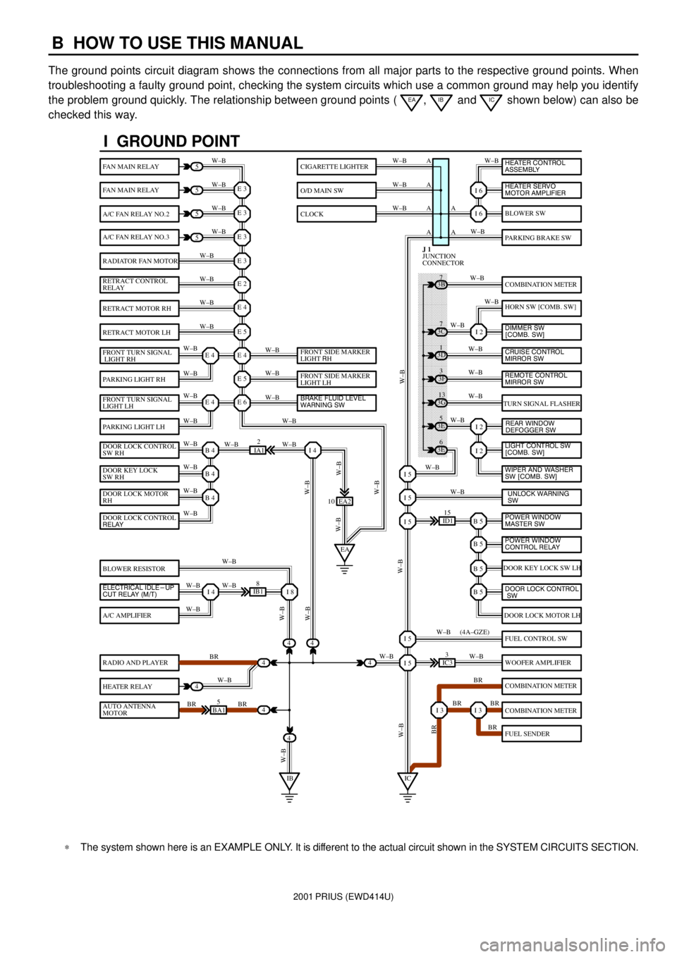
The ground points circuit diagram shows the connections from all major parts to the respective ground points. When
troubleshooting a faulty ground point, checking the system circuits which use a common ground may help you identify
the problem ground quickly. The relationship between ground points (
EA, IB and IC shown below) can also be
checked this way.
���� ���� ���� ���� ���� ���� ���� ���� ���� ���� ���� ���� ���� ���� ���� ���� ���� ���� ����
I GROUND POINT
FAN MAIN RELAY
FAN MAIN RELAY
A/C FAN RELAY NO.2
A/C FAN RELAY NO.3
RADIATOR FAN MOTOR
RETRACT CONTROL
RELAY
RETRACT MOTOR RH
RETRACT MOTOR LH
FRONT TURN SIGNAL
LIGHT RH
PARKING LIGHT RH
FRONT TURN SIGNAL
LIGHT LH
PARKING LIGHT LH
DOOR LOCK CONTROL
SW RH
DOOR KEY LOCK
SW RH
DOOR LOCK MOTOR
RH
BLOWER RESISTOR
A/C AMPLIFIER
RADIO AND PLAYER
HEATER RELAY
AUTO ANTENNA
MOTOR
BLOWER SW
PARKING BRAKE SW
COMBINATION METER
HORN SW [COMB. SW]
TURN SIGNAL FLASHER
DOOR KEY LOCK SW LH
DOOR LOCK MOTOR LH
FUEL CONTROL SW
WOOFER AMPLIFIER
COMBINATION METER
COMBINATION METER
FUEL SENDER
CIGARETTE LIGHTER
O/D MAIN SW
CLOCK
5
5
5
5
4
4
4
4
4BA15
IB18
EA2 10
3E5
3E
6 3G
13 3F
3 3D
1 3B
7
ID115
IC33
IA12
E 3
A
A AW±B
W±BW±B W±B
W±B W±B
W±B
W±B
W±B
W±B
W±B
W±B
W±B
W±B
W±B W±BW±B W±B W±B W±B
W±B W±B
W±BW±B
W±B
W±B
W±B W±B
W±B
BR
W±B
BR BRW±BW±B
W±B
W±B
W±B
W±B
W±B
W±B
W±B
W±B
W±B W±B
W±B
W±B
W±B
W±B
BR W±B
BR BR
BR W±B W±BW±B
W±BW±BBR W±B (4A±GZE)
W±B A A A
I 6
I 6
I 2
I 2
I 2
B 5I 5
I 5
I 5
B 5
B 5
B 5
I 5
I 5
I 3I 3
E 3
E 3
E 3
E 2
E 4
E 5
E 4
E 5
E 6E 4
E 4
B 4
EAI 4
B 4
B 4
I 4I 8
IBIC
3C7
4
JUNCTION
CONNECTOR J 1
4
DOOR LOCK CONTROL
RELAY
ELECTRICAL IDLE-UP
CUT RELAY (M/T)FRONT SIDE MARKER
LIGHT RH
FRONT SIDE MARKER
LIGHT LH
BRAKE FLUID LEVEL
WARNING SW
UNLOCK WARNING
SW WIPER AND WASHER
SW [COMB. SW] LIGHT CONTROL SW
[COMB. SW] HEATER CONTROL
ASSEMBLY
HEATER SERVO
MOTOR AMPLIFIER
DIMMER SW
[COMB. SW]
CRUISE CONTROL
MIRROR SW
REAR WINDOW
DEFOGGER SW
POWER WINDOW
MASTER SW
POWER WINDOW
CONTROL RELAY
DOOR LOCK CONTROL
SW
REMOTE CONTROL
MIRROR SW
*The system shown here is an EXAMPLE ONLY. It is different to the actual circuit shown in the SYSTEM CIRCUITS SECTION.
Page 9 of 1943
2001 PRIUS (EWD414U)
B
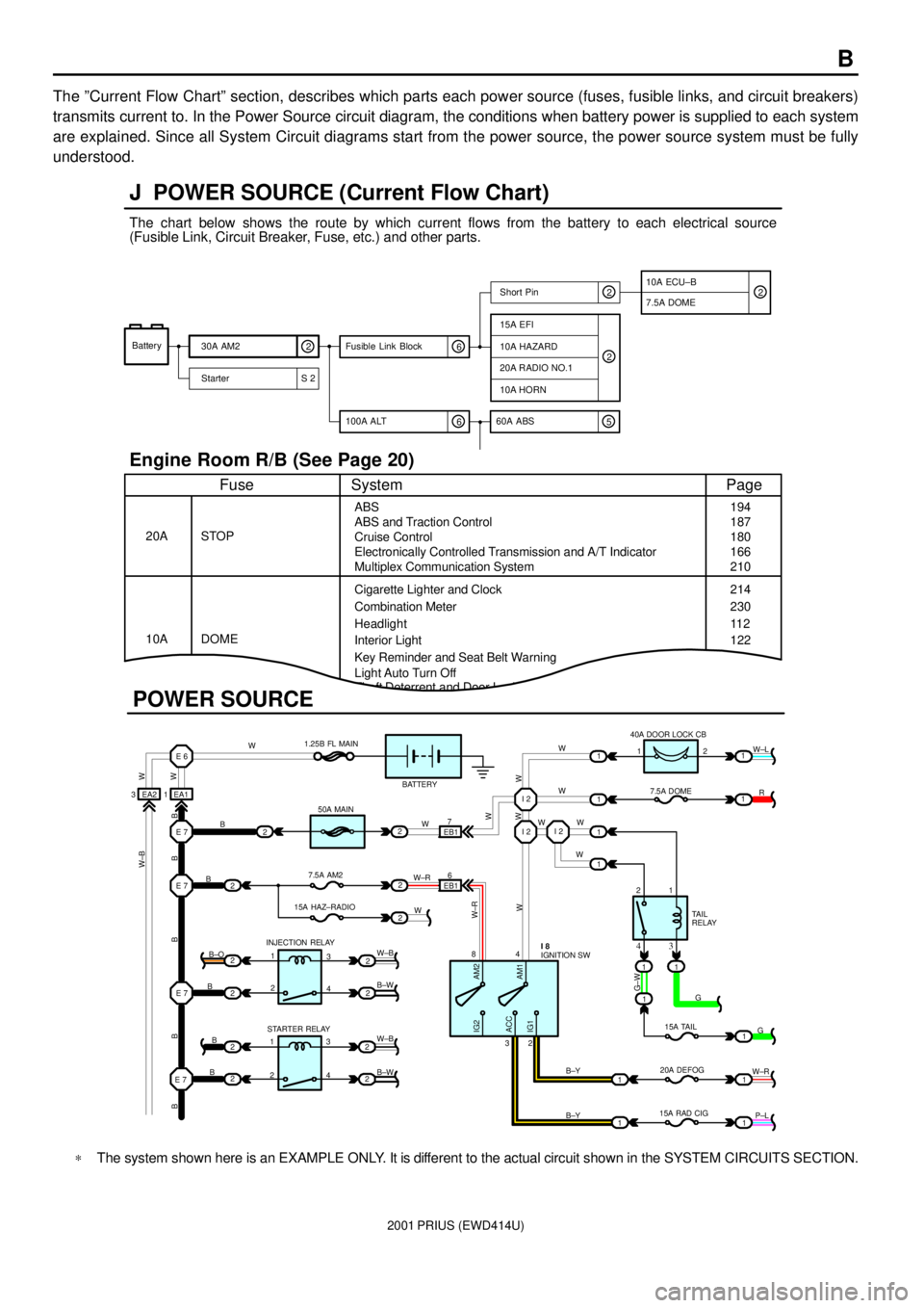
The ºCurrent Flow Chartº section, describes which parts each power source (fuses, fusible links, and circuit breakers)
transmits current to. In the Power Source circuit diagram, the conditions when battery power is supplied to each system
are explained. Since all System Circuit diagrams start from the power source, the power source system must be fully
understood.
Theft Deterrent and Door Lock Control
J POWER SOURCE (Current Flow Chart)
11
1
EA1 1EA2 3
7
EB16
E 6
E 7I 2I 2
I 2
E 7
E 7
E 7
2
1
1
2
2
2
2
2
B
B
W W
B B B B BW±B
B
B
B B±O
B±W
W±B
B±W STARTER RELAY INJECTION RELAY15A HAZ±RADIO7.5A AM250A MAIN 1.25B FL MAIN
BATTERY
WWW
W W W
R W±L
W
W
G±W
G
15A TAIL
20A DEFOG
15A RAD CIGTA I L
RELAY 7.5A DOME 40A DOOR LOCK CB
2 1
1 2
4 8
2 3
3 4
G
W±R
P±L B±Y
B±Y
W±R
AM2 IG2
ACC
IG1AM1W W
W±R
W W
W±B
21
1
1
1
1
2
2
2
2
3
4
3
4 1
2
1
22
1
11
1
IGNITION SW I 8
Battery
30A AM2
2
Starter S 220A RADIO NO.1
10A HORN
15A EFI
7.5A DOMEShort Pin
10A HAZARD
The chart below shows the route by which current flows from the battery to each electrical source
(Fusible Link, Circuit Breaker, Fuse, etc.) and other parts.
Engine Room R/B (See Page 20)
ABS
ABS and Traction Control
Cruise Control
Electronically Controlled Transmission and A/T Indicator
Multiplex Communication System
Cigarette Lighter and Clock
Key Reminder and Seat Belt Warning STOP
Fuse Page
194
214
11 2
System
DOME 20A
10ACombination Meter
Headlight
Interior Light
2
2
6 100A ALT
EB1
POWER SOURCE
Light Auto Turn Off187
180
166
210
230
122
10A ECU±B
5 60A ABS
2
6 Fusible Link Block2
*The system shown here is an EXAMPLE ONLY. It is different to the actual circuit shown in the SYSTEM CIRCUITS SECTION.
Page 11 of 1943
![TOYOTA PRIUS 2001 Service Repair Manual 2001 PRIUS (EWD414U)
B
[A]: Part Code
[B]: Part Name
[C]: Part Number
Toyota Part Number are indicated.
Not all of the above part numbers of the connector are established for the supply. In case of or TOYOTA PRIUS 2001 Service Repair Manual 2001 PRIUS (EWD414U)
B
[A]: Part Code
[B]: Part Name
[C]: Part Number
Toyota Part Number are indicated.
Not all of the above part numbers of the connector are established for the supply. In case of or](/manual-img/14/57461/w960_57461-10.png)
2001 PRIUS (EWD414U)
B
[A]: Part Code
[B]: Part Name
[C]: Part Number
Toyota Part Number are indicated.
Not all of the above part numbers of the connector are established for the supply. In case of ordering a connector
or terminal with wire, please confirm in advance if there is supply for it using
ªParts Catalog Newsº (published by
Parts Engineering Administration Dept.).
A 5�� ��
90980±11194
L PART NUMBER OF CONNECTORS
Code Part Name Part NumberCode Part NamePart Number
A 1
A 2
A 4
A 6
A 7A/C Ambient Temp. Sensor
A/C Condenser Fan Motor
A/C Triple Pressure SW (A/C Dual and
Single Pressure SW)
A/T Oil Temp. Sensor
ABS Actuator
ABS Actuator90980±11070
90980±11237
90980±10943
90980±11413
90980±11151D 4
D 5
D 6
D 7
D 8
D 9
D10
D11Diode (Door Courtesy Light)
Diode (Key Off Operation)
Diode (Luggage Compartment Light)
Door Lock Control Relay
Door Courtesy Light LH
Door Courtesy Light RH
Door Courtesy SW LH
Door Courtesy SW RH90980±11608
90980±10962
90980±11608
90980±10848
90980±11148
90980±11097
A 8ABS Speed Sensor Front LH
90980±10941
A 9ABS Speed Sensor Front RH
90980±11856 A10Airbag Sensor Front LH
A11Airbag Sensor Front RHD12Door Courtesy SW Front LH
90980±11156 D13Door Courtesy SW Front RH
D14Door Courtesy SW Rear LH
Door Courtesy SW Rear RH
D15
[B]�� ��[C]
A12
Auto Antenna Motor90980±11194 A 3
A/C Condenser Fan Relay90980±10940
[A]
90980±11009
90980±11002
D16
D17Door Key Lock and Unlock SW LH
Door Key Lock and Unlock SW RH90980±11170
Page 37 of 1943

2001 PRIUS (EWD414U)
G
Position of Parts in Instrument Panel
G 1 Gateway ECU
H 7 Hazard Warning SW
H 8 Hazard Warning SW
H 9 Heated Oxygen Sensor (Bank 1 Sensor 2)
H 10 Hybrid Vehicle Control ECU
H 11 Hybrid Vehicle Control ECU
H 12 Hybrid Vehicle Control ECU
H 13 Hybrid Vehicle Control ECU
H 14 Hybrid Vehicle Control ECU
I 15 Ignition SW
J 1 Junction Connector
J 2 Junction Connector
J 3 Junction Connector
J 4 Junction Connector
J 5 Junction Connector
J 6 Junction Connector
J 7 Junction Connector
J 8 Junction Connector
J 9 Junction Connector
J 10 Junction Connector
J 11 Junction Connector
J 12 Junction Connector
J 13 Junction Connector
J 14 Junction Connector
J 15 Junction Connector
J 16 Junction Connector
J 17 Junction Connector
J 18 Junction Connector
J 19 Junction Connector
J 20 Junction Connector
J 21 Junction ConnectorJ 22 Junction Connector
J 23 Junction Connector
J 24 Junction Connector
J 25 Junction Connector
J 26 Junction Connector
J 27 Junction Connector
J 28 Junction Connector
J 29 Junction Connector
L 1 Light Control Rheostat
M 5 Multi Display
M 6 Multi Display
M 7 Multi Display
P 1 Park/Neutral Position SW
P 2 Parking Brake SW
P 3 PTC Heater
P 4 PTC Heater
R 2 Radio and Player
R 3 Radio and Player
R 4 Radio and Player
R 5 Remote Control Mirror SW
S 2 Shift Lock ECU
S 3 Stop Light SW
T 4 Transponder Key Computer
T 5 Turn Signal Flasher Relay
U 1 Unlock Warning SW and Key Interlock Solenoid
W 5 Wireless Door Control Receiver
Page 38 of 1943

2001 PRIUS (EWD414U)
G ELECTRICAL WIRING ROUTING
Position of Parts in Body
A 23 ABS Speed Sensor Rear LH
A 24 ABS Speed Sensor Rear RH
B 15 Battery Blower Motor
B 16 Battery Blower Motor Controller
B 17 Battery ECU
B 18 Battery ECU
B 19 Battery Fan Relay
B 20 Buckle SW and Tension Reducer LH
B 21 Buckle SW RH and
Seat Belt Warning Occupant Detection Sensor
D 6 Door Courtesy SW Front LH
D 7 Door Courtesy SW Front RH
D 8 Door Courtesy SW Rear LH
D 9 Door Courtesy SW Rear RH
D 10 Door Lock Control SW Front RH
D 11 Door Lock Motor and Door Unlock Detection SW
Rear LH
D 12 Door Lock Motor and Door Unlock Detection SW
Rear RH
D 13 Door Lock Motor, Door Key Lock and Unlock SW and
Door Unlock Detection SW Front LH
D 14 Door Lock Motor, Door Key Lock and Unlock SW and
Door Unlock Detection SW Front RHF 14 Front Door Speaker LH
F 15 Front Door Speaker RH
F 16 Fuel Pump and Fuel Sender
F 17 Fusible Link Block No.2
F 18 Fusible Link Block No.2
H 15 High Mounted Stop Light
H 16 Hybrid Vehicle Battery
H 17 Hybrid Vehicle Battery
I 16 Interior Light
I 17 Interlock SW
J 30 Junction Connector
J 31 Junction Connector
J 32 Junction Connector
J 33 Junction Connector
L 2 License Plate Light LH
L 3 License Plate Light RH
L 4 Luggage Compartment Door Unlock SW
L 5 Luggage Compartment Light
L 6 Luggage Compartment Light SW
Page 76 of 1943
2001 PRIUS (EWD414U)
HYBRID VEHICLE IMMOBILISER SYSTEM
7. 5A
ECU±B FROM POWER SOURCE SYSTEM (
SEE PAGE 50)
2C 5
A A AA F
B H
5JUNCTION
CONNECTOR J20
JUNCTION
CONNECTOR J11 1
12
R±G R±G R±G LG±B
W±B W± B W±B
+B HEVC
IND
JUNCTION
CONNECTORB J27 A , J28
ID2 10 ID2 11 76
15A
AM2
1B 21J 92C 2
2G 1
D 1C 1
120A MAIN
1AM2 IG2
ST2
IFC 8
B 7B E
A A
JUNCTION
CONNECTORB J27 A , J28
JUNCTION
CONNECTORB J27 A , J28
B F
A D
JUNCTION
CONNECTORB J12 A , J13
B D
A B
JUNCTION
CONNECTORB J27 A , J28
A A
B A
JUNCTION
CONNECTORB J24 A , J25
ID A A
2D 8
1 2ID1 9B B
IB1 3
1 ID2 8
JUNCTION
CONNECTOR J10
JUNCTION
CONNECTOR J20
46711 7
238
6DATA LINK
CONNECTOR 3 D 2
HYBRID VEHICLE
CONTROL ECU H14
CENTER
CLUSTER SW C 7
DOOR COURTESY
SW FRONT LH D 6
UNLOCK WARNING SW U 1RADIO AND PLAYERC R 3 B , R 4FUSIBLE LINK
BLOCK NO. 1D F1 2 C , F13 BATTERYB±G B W±R W±R
B±W B±W B±W
B±R
B±WB±R R±W
L±B
W±BL±B L±B L±B
W±BR±W R±WLG±B BR BR
LG±B
2K 8
A IG D
KSW CTY
LG±B
FUSIBLE LINK
BLOCK NO. 2 F18
W±B
W± B ID1 8
R±G
IGNITION SW I15
OP1 FC VC
GND
TRANSPONDER KEY
COMPUTER T 4 A C
A CJUNCTION
CONNECTORJ24 A
Page 112 of 1943
2001 PRIUS (EWD414U)
KEY REMINDER AND LIGHT REMINDER BUZZER
120A MAIN
1B 1C1
D 11B 1130A
HEAD
1 2
32 41
1F 823 15
7. 5A
TAI L10A
GAUGE FROM POWER SOURCE SYSTEM (
SEE PAGE 50)
2K 62H 1
B 2B11ID2 2 IA2 6
ID2 3
B 17 B18
IG ID2 5ID262K 1
B F
A D
IB1 3
1 16 7
E6
E
13 14
A17 15
T HR±W R±WW
B W B±G
LG LGR±G R±G R±G R±G R±W R
LG±R R
LG±R W±B
R±W R±W R±W
2
(
*1) (
*1) (
*1)
R±W
(
*2)
(
*2)
(
*2) (
*1)H
HRLY TRLYH±LP
TAI L REL AY HEAD RELAYSHORT PIN
JUNCTION
CONNECTOR J20DAYTIME RUNNING
LIGHT RELAY D 3
OFF
TAIL
HEAD
100A DC/DC
FUSIBLE LINK
BLOCK NO. 2 F1 8
FUSIBLE LINK
BLOCK NO. 1C F11 B , F1 2
JUNCTION
CONNECTORB J12 A , J13
DOOR COURTESY
SW FRONT LH D 6
JUNCTION
CONNECTOR J17LIGHT CONTROL SW
[COMB. SW] C13
D , F13
BATTERY3 (
*1)
(
*2)
(
*2)
(
*1)
BODY ECUB B 8 , B 9AL 7. 5A
ECU±B
2C 5 2A 5
R±G
B 9F F
R±G
JUNCTION
CONNECTOR J2 7
DCTYTAIL IG B
Page 114 of 1943
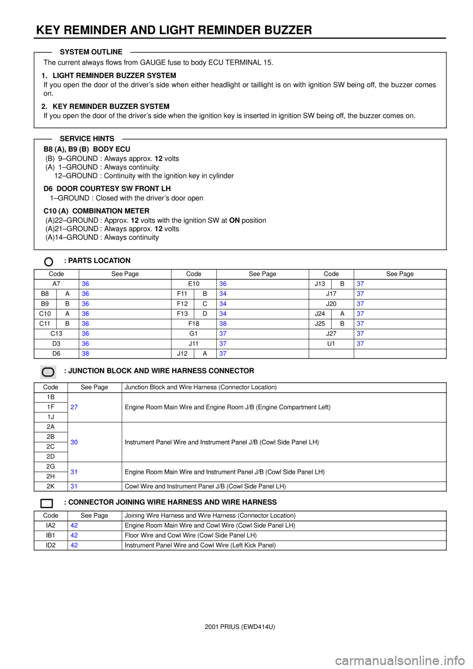
2001 PRIUS (EWD414U)
KEY REMINDER AND LIGHT REMINDER BUZZER
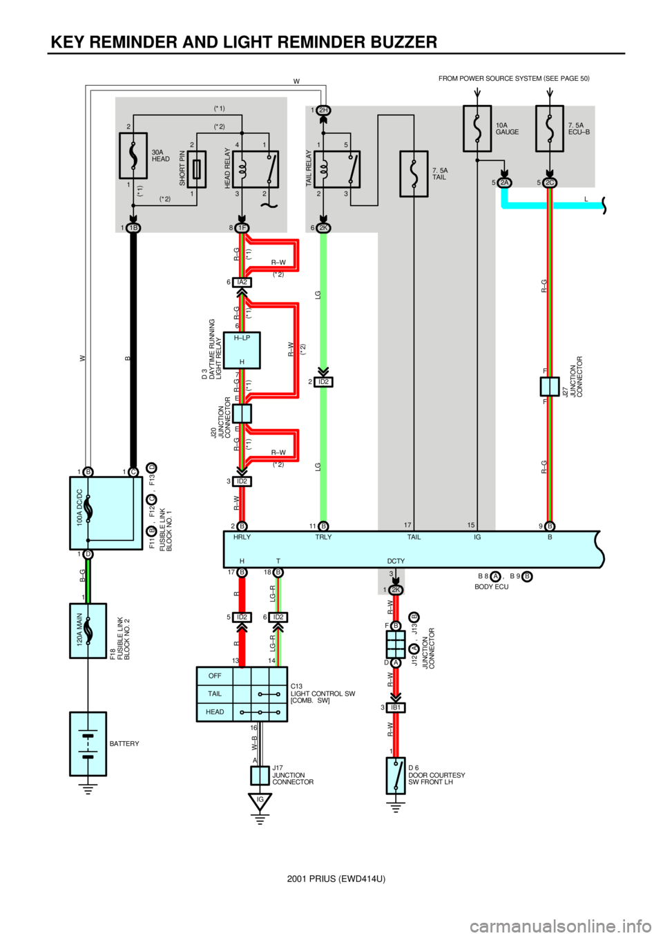
The current always flows from GAUGE fuse to body ECU TERMINAL 15.
1. LIGHT REMINDER BUZZER SYSTEM
If you open the door of the driver's side when either headlight or taillight is on with ignition SW being off, the buzzer comes
on.
2. KEY REMINDER BUZZER SYSTEM
If you open the door of the driver's side when the ignition key is inserted in ignition SW being off, the buzzer comes on.
B8 (A), B9 (B) BODY ECU
(B) 9±GROUND : Always approx. 12 volts
(A) 1±GROUND : Always continuity
12±GROUND : Continuity with the ignition key in cylinder
D6 DOOR COURTESY SW FRONT LH
1±GROUND : Closed with the driver's door open
C10 (A) COMBINATION METER
(A)22±GROUND : Approx. 12 volts with the ignition SW at ON position
(A)21±GROUND : Always approx. 12 volts
(A)14±GROUND : Always continuity
: PARTS LOCATION
CodeSee PageCodeSee PageCodeSee Page
A736E1036J13B37
B8A36F11B34J1737
B9B36F12C34J2037
C10A36F13D34J24A37
C11B36F1838J25B37
C1336G137J2737
D336J1137U137
D638J12A37
������ ���: JUNCTION BLOCK AND WIRE HARNESS CONNECTOR
CodeSee PageJunction Block and Wire Harness (Connector Location)
1B
1F27Engine Room Main Wire and Engine Room J/B (Engine Compartment Left)
1J
gg(g)
2A
2B30Instrument Panel Wire and Instrument Panel J/B (Cowl Side Panel LH)2C30Instrument Panel Wire and Instrument Panel J/B (Cowl Side Panel LH)
2D
2G31Engine Room Main Wire and Instrument Panel J/B (Cowl Side Panel LH)2H31Engine Room Main Wire and Instrument Panel J/B (Cowl Side Panel LH)
2K31Cowl Wire and Instrument Panel J/B (Cowl Side Panel LH)
: CONNECTOR JOINING WIRE HARNESS AND WIRE HARNESS
CodeSee PageJoining Wire Harness and Wire Harness (Connector Location)
IA242Engine Room Main Wire and Cowl Wire (Cowl Side Panel LH)
IB142Floor Wire and Cowl Wire (Cowl Side Panel LH)
ID242Instrument Panel Wire and Cowl Wire (Left Kick Panel)
SYSTEM OUTLINE
SERVICE HINTS