Page 741 of 2572
F46304
Combination Meter
Passenger Side J/BABS C11
Instrument Panel J/BSkid Control ECU with Actuator
I15
Ignition SW
F7
FL BlockC11 IF2
IL1 IC4 S27
S27 S27 4E
4H 4JJ6
J/C
IC4
IC1 1A
1C 1D
1G
1C 1C ECU-IG
IGN
AM1IG1 4M
IG2AM1
AM2WA
IG1
GND1
EA EB ALT
AM2
J4
J/C FL MAIN
Battery1
24 6
7 9
10 13
1729
4
446
4
62
10
32 12
12
1 E P W SB R-L
P
ESB
GRB-R
G
GR
W
Y
L-Y WB
W-B Y
W
AW-B 167 10
1
6 05-840
- DIAGNOSTICSABS WITH EBD & BA & TRAC & VSC SYSTEM
1030 Author�: Date�:
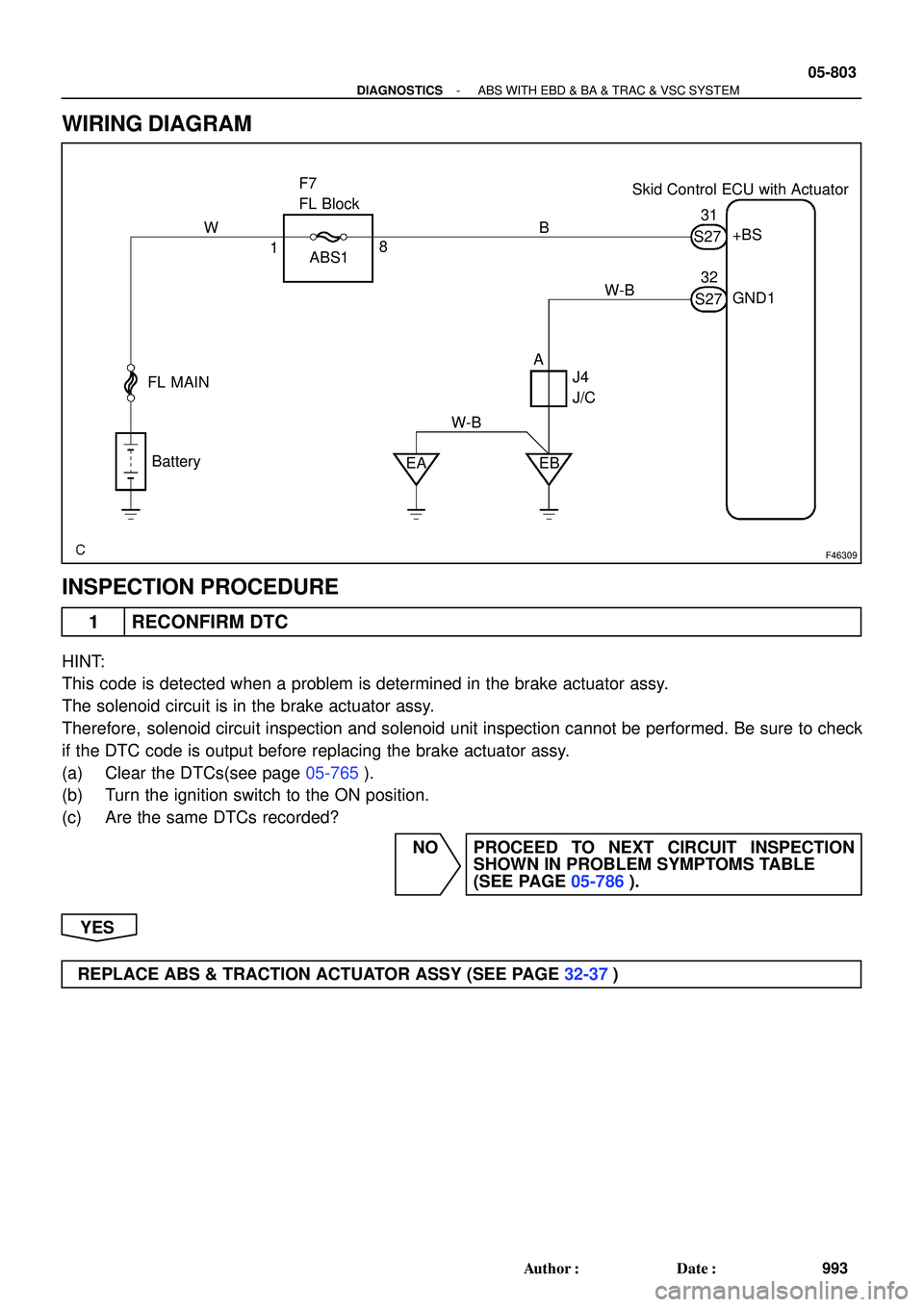
ABS WARNING LIGHT CIRCUIT (REMAINS ON)
CIRCUIT DESCRIPTION
During DTC read by SST (CHECK WIRE), if the ABS warning light remains on, troubleshoot by following
this inspection flow.
WIRING DIAGRAM
05CDG-1 1
Page 745 of 2572
F50610
Skid Control ECU with Actuator Combination Meter
B4
Brake Warning SW
Passenger Side J/B
Instrument Panel J/B
I15
Ignition SW
F7
FL Block Brake
IGN
AM2BRL
PKB
AM2 IG2
FL MAIN
BatteryC11 IF3 IC4 S27
IL1
S27 C12
C12IF3
IC4
4E 4M
1C
1G4J
4MIC4
IC1Passenger Side J/B
P3
Parking
Brake SW J4
J/C
EB1
2
3 46
791011 13
1644
15
1
28 J6
J/C
11
9
16
6
1
10
1 1
1 B
PR V
W YSB
P
EER-B SB
R-W
LG
B
A L-Y GRW W-B
LG-B
05-854
- DIAGNOSTICSABS WITH EBD & BA & TRAC & VSC SYSTEM
1044 Author�: Date�:
BRAKE WARNING LIGHT CIRCUIT
CIRCUIT DESCRIPTION
The BRAKE warning light comes on when the brake fluid is insufficient, the parking brake is applied or the
EBD is defective.
WIRING DIAGRAM
05F1V-09
Page 750 of 2572
F46304
Combination Meter
Passenger Side J/BABS C11
Instrument Panel J/BSkid Control ECU with Actuator
I15
Ignition SW
F7
FL BlockC11 IF2
IL1 IC4 S27
S27 S27 4E
4H 4JJ6
J/C
IC4
IC1 1A
1C 1D
1G
1C 1C ECU-IG
IGN
AM1IG1 4M
IG2AM1
AM2WA
IG1
GND1
EA EB ALT
AM2
J4
J/C FL MAIN
Battery1
24 6
7 9
10 13
1729
4
446
4
62
10
32 12
12
1 E P W SB R-L
P
ESB
GRB-R
G
GR
W
Y
L-Y WB
W-B Y
W
AW-B 167 10
1
6 05-844
- DIAGNOSTICSABS WITH EBD & BA & TRAC & VSC SYSTEM
1034 Author�: Date�:
ABS WARNING LIGHT CIRCUIT (DOES NOT LIGHT UP)
WIRING DIAGRAM
05F1T-06
Page 785 of 2572
F46309
Skid Control ECU with Actuator F7
FL Block
FL MAIN
Battery
EA EB ABS1+BS
GND1
J4
J/C 1831
32
AB W
W-BS27
S27 W-B
- DIAGNOSTICSABS WITH EBD & BA & TRAC & VSC SYSTEM
05-803
993 Author�: Date�:
WIRING DIAGRAM
INSPECTION PROCEDURE
1 RECONFIRM DTC
HINT:
This code is detected when a problem is determined in the brake actuator assy.
The solenoid circuit is in the brake actuator assy.
Therefore, solenoid circuit inspection and solenoid unit inspection cannot be performed. Be sure to check
if the DTC code is output before replacing the brake actuator assy.
(a) Clear the DTCs(see page 05-765).
(b) Turn the ignition switch to the ON position.
(c) Are the same DTCs recorded?
NO PROCEED TO NEXT CIRCUIT INSPECTION
SHOWN IN PROBLEM SYMPTOMS TABLE
(SEE PAGE 05-786).
YES
REPLACE ABS & TRACTION ACTUATOR ASSY (SEE PAGE 32-37)
Page 786 of 2572
05-804
- DIAGNOSTICSABS WITH EBD & BA & TRAC & VSC SYSTEM
994 Author�: Date�:
DTC C0273/13 OPEN CIRCUIT IN ABS MOTOR RELAY
CIRCUIT
DTC C0274/14 SHORT CIRCUIT IN ABS MOTOR RELAY
CIRCUIT
DTC C1361/91 SHORT CIRCUIT IN ABS MOTOR FAIL SAFE
RELAY CIRCUIT
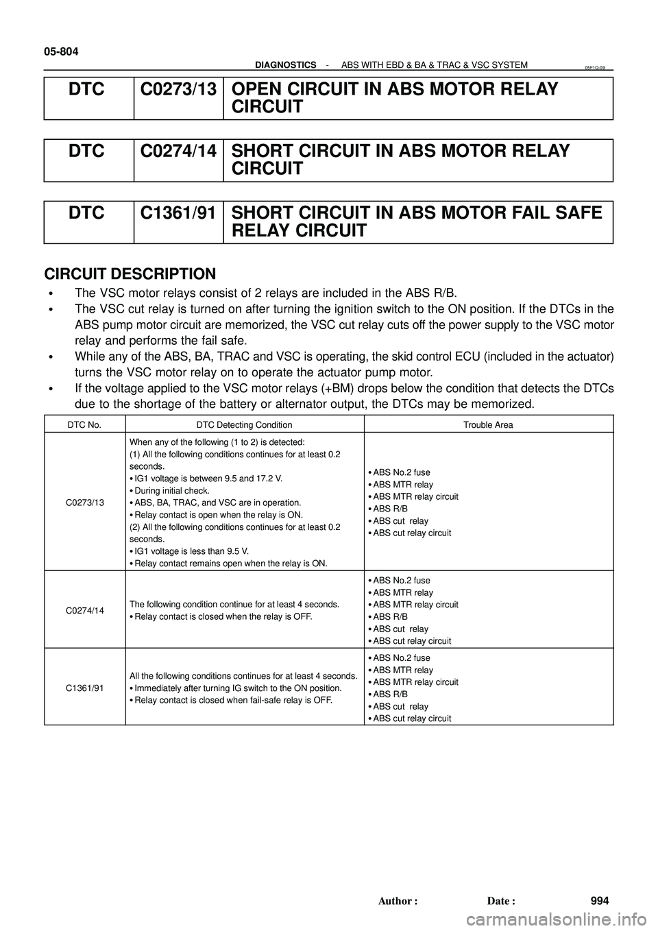
CIRCUIT DESCRIPTION
�The VSC motor relays consist of 2 relays are included in the ABS R/B.
�The VSC cut relay is turned on after turning the ignition switch to the ON position. If the DTCs in the
ABS pump motor circuit are memorized, the VSC cut relay cuts off the power supply to the VSC motor
relay and performs the fail safe.
�While any of the ABS, BA, TRAC and VSC is operating, the skid control ECU (included in the actuator)
turns the VSC motor relay on to operate the actuator pump motor.
�If the voltage applied to the VSC motor relays (+BM) drops below the condition that detects the DTCs
due to the shortage of the battery or alternator output, the DTCs may be memorized.
DTC No.DTC Detecting ConditionTrouble Area
C0273/13
When any of the following (1 to 2) is detected:
(1) All the following conditions continues for at least 0.2
seconds.
�IG1 voltage is between 9.5 and 17.2 V.
�During initial check.
�ABS, BA, TRAC, and VSC are in operation.
�Relay contact is open when the relay is ON.
(2) All the following conditions continues for at least 0.2
seconds.
�IG1 voltage is less than 9.5 V.
�Relay contact remains open when the relay is ON.
�ABS No.2 fuse
�ABS MTR relay
�ABS MTR relay circuit
�ABS R/B
�ABS cut relay
�ABS cut relay circuit
C0274/14The following condition continue for at least 4 seconds.
�Relay contact is closed when the relay is OFF.
�ABS No.2 fuse
�ABS MTR relay
�ABS MTR relay circuit
�ABS R/B
�ABS cut relay
�ABS cut relay circuit
C1361/91
All the following conditions continues for at least 4 seconds.
�Immediately after turning IG switch to the ON position.
�Relay contact is closed when fail-safe relay is OFF.
�ABS No.2 fuse
�ABS MTR relay
�ABS MTR relay circuit
�ABS R/B
�ABS cut relay
�ABS cut relay circuit
05F1Q-09
Page 787 of 2572
F46308
Skid Control ECU with Actuator
ABS MTR Relay
ABS CUT Relay
FL MAIN
BatteryS27
S27
S27
S27
ABS2 F7
FL Block ABS R/BR+
MR
BM
MRF 12
3 5
91415 45
5
55
55
555
1
2 35
12
B
W B-OLG
W-L
B-R
G-RB-O
- DIAGNOSTICSABS WITH EBD & BA & TRAC & VSC SYSTEM
05-805
995 Author�: Date�:
WIRING DIAGRAM
Page 791 of 2572
F46309
Skid Control ECU with Actuator F7
FL Block
FL MAIN
Battery
EA EB ABS1+BS
GND1
J4
J/C 1831
32
AB W
W-BS27
S27 W-B
- DIAGNOSTICSABS WITH EBD & BA & TRAC & VSC SYSTEM
05-809
999 Author�: Date�:
DTC C0278/11 OPEN CIRCUIT IN ABS SOLENOID RELAY
CIRCUIT
DTC C0279/12 SHORT CIRCUIT IN ABS SOLENOID RELAY
CIRCUIT
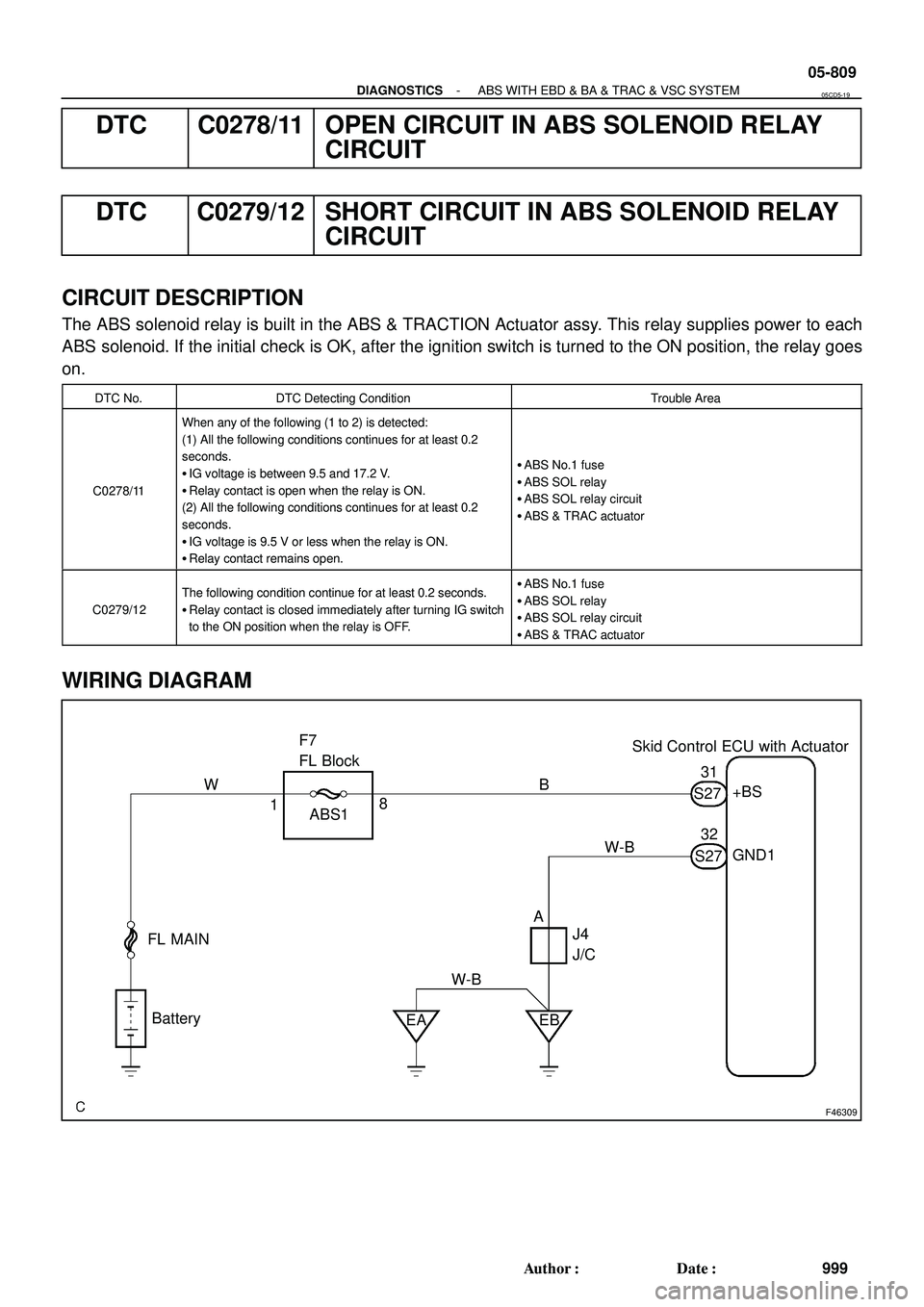
CIRCUIT DESCRIPTION
The ABS solenoid relay is built in the ABS & TRACTION Actuator assy. This relay supplies power to each
ABS solenoid. If the initial check is OK, after the ignition switch is turned to the ON position, the relay goes
on.
DTC No.DTC Detecting ConditionTrouble Area
C0278/11
When any of the following (1 to 2) is detected:
(1) All the following conditions continues for at least 0.2
seconds.
�IG voltage is between 9.5 and 17.2 V.
�Relay contact is open when the relay is ON.
(2) All the following conditions continues for at least 0.2
seconds.
�IG voltage is 9.5 V or less when the relay is ON.
�Relay contact remains open.
�ABS No.1 fuse
�ABS SOL relay
�ABS SOL relay circuit
�ABS & TRAC actuator
C0279/12
The following condition continue for at least 0.2 seconds.
�Relay contact is closed immediately after turning IG switch
to the ON position when the relay is OFF.�ABS No.1 fuse
�ABS SOL relay
�ABS SOL relay circuit
�ABS & TRAC actuator
WIRING DIAGRAM
05CD5-19
Page 804 of 2572
F46318
S14
Steering SensorSkid Control ECU
with Actuator
Passenger Side J/B
Instrument Panel J/B
Passenger Side J/B
Instrument Panel J/B
Engine Room J/B I15
Ignition SW
F7 FL Block
FL
MAIN
BatteryJ17
J/C
AM1IG1ECU-IG
ALT
D.C.C ECU-B
IC AM1IC4 S27
IC4
IC3S27
1A 1C 1D 1G
2A 2I4C
4J4N
4L
4C
1C1D J16
J/C
1 2
3
45
67 8 9
1011 19 2125
1012 13
31
910
11
710
1
4 1 24
12
3B L W
YW W
E PP
E
LY
G
W
B
W W
W-L W-B W-B
W-B
BR CANL
ESS
IG1 CANH
BATCANL
CANH
1 2 05-822
- DIAGNOSTICSABS WITH EBD & BA & TRAC & VSC SYSTEM
1012 Author�: Date�:
WIRING DIAGRAM