Page 2460 of 2572

F46317
Instrument Panel J/BSkid Control ECU
with Actuator
F7
FL Block I15
Ignition SWPassenger Side J/B
4
1
FL MAIN IG1
Battery 4JS27BZ
630
B 1C 1DV8
VSC Warning
Buzzer ECU-IG
W8
1A AM1
W
2 710
ALT4M
1 AM1G
1C
2
11 2
BR-WIC420
Y G
4 2O
05-866
- DIAGNOSTICSABS WITH EBD & BA & TRAC & VSC SYSTEM
1056 Author�: Date�:
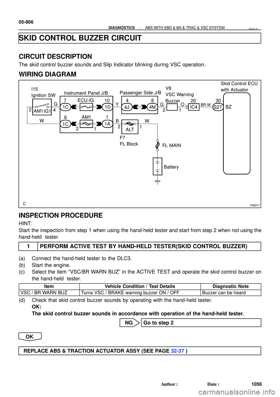
SKID CONTROL BUZZER CIRCUIT
CIRCUIT DESCRIPTION
The skid control buzzer sounds and Slip Indicator blinking during VSC operation.
WIRING DIAGRAM
INSPECTION PROCEDURE
HINT:
Start the inspection from step 1 when using the hand-held tester and start from step 2 when not using the
hand-held tester.
1 PERFORM ACTIVE TEST BY HAND-HELD TESTER(SKID CONTROL BUZZER)
(a) Connect the hand-held tester to the DLC3.
(b) Start the engine.
(c) Select the item ºVSC/BR WARN BUZº in the ACTIVE TEST and operate the skid control buzzer on
the hand-held tester.
ItemVehicle Condition / Test DetailsDiagnostic Note
VSC / BR WARN BUZTurns VSC / BRAKE warning buzzer ON / OFFBuzzer can be heard
(d) Check that skid control buzzer sounds by operating with the hand-held tester.
OK:
The skid control buzzer sounds in accordance with operation of the hand-held tester.
NG Go to step 2
OK
REPLACE ABS & TRACTION ACTUATOR ASSY (SEE PAGE 32-37)
05CDL-18
Page 2462 of 2572
F46302
1A
1C E5
E6IC4 S27
C11 E5 IC4 S27
E5 IC4
S27
E5 IC4 S27
E6 C12C11
1C1K 3A 3C1 5
678
9
13 1819
2122
23
24 25
2930 31
18
9
7
1
1
1 27 4
24 ECMSkid Control ECU with Actuator
Combination Meter
Instrument Panel J/B
Center J/B
F7
FL Block I15
Ignition SW
FL MAIN
Battery TRC-
ENG-
MPX
SystemSlip
HEATER
AM1 IG1
ALT AM1 TRC+
ENG+
MPX2TRC-
ENG- TRC+
ENG+
B G
R
V YY-B
G-B
W-G
W-L
P
G
WB MPX1
2 W
- DIAGNOSTICSABS WITH EBD & BA & TRAC & VSC SYSTEM
05-863
1053 Author�: Date�:
SLIP INDICATOR LIGHT CIRCUIT
CIRCUIT DESCRIPTION
The SLIP indicator blinks during TRAC & VSC operation.
WIRING DIAGRAM
05CDK-07
Page 2484 of 2572
F46300
1A 1C
3F 3J E5
E6IC4 S27
C11
IF3 E5 IC4 S27
E5 IC4 S27
E5 IC4 S27
E6 C12C11
S27 IC4 1C1K
3A3C
IB 1
2
45
67
8
9
13
17 1819
2122
23
24 25
2930 31
43 18
9
7
1
1
1
413 1
27 4
13 24 ECM
Skid Control ECU with Actuator
Combination Meter
Instrument Panel J/BCenter J/B
F7
FL Block I15
Ignition SW
Center J/B
FL MAIN
BatteryT6
Trac Off SW TRC-
ENG-
MPX
SystemTRAC
OFF
HEATER
AM1 IG1
ALT
CSW AM1 TRC+
ENG+
MPX2TRC-
ENG- TRC+
ENG+
B G
R
V
WYY-B
G-B
W-G
W-L
P
WW G
WB
L-R
W-B
W-B MPX1
(*1) (*1) (*1)
(*1)
*1 : 2WD
- DIAGNOSTICSABS WITH EBD & BA & TRAC & VSC SYSTEM
05-859
1049 Author�: Date�:
TRAC OFF INDICATOR LIGHT, TRAC OFF SWITCH CIRCUIT
CIRCUIT DESCRIPTION
The skid control ECU detects the track control main switch ON/OFF signal and turns the track off light on/off.
This is the TRAC control main switch. When the TRAC control switch is pressed, the TRAC control does not
operate and the TRAC OFF light comes on.
WIRING DIAGRAM
05H3X-03
Page 2502 of 2572
F46303
Combination MeterSkid Control ECU with Actuator
Instrument Panel J/BI15
Ignition SW
F7
FL BlockECU-IG
IGN
AM1
ALT
AM2VSC
IG1 AM1VSCW
IG1
FL MAIN
BatteryIG2 AM2 IF3IC2
S27
IL1
S27 IC4 C11
J6
J/C Passenger Side J/B
IC1 C12
4E
4H 4J 4M
1A1C
1D
1C
1C 1G 1
2 45
6 7
1013 1636
9
4
11 7
6
642
746
10
1 12
10 PV
L-Y
SB
PP
WYEE
GR B-R
G
GR
W
Y B W
L-Y12
- DIAGNOSTICSABS WITH EBD & BA & TRAC & VSC SYSTEM
05-847
1037 Author�: Date�:
VSC WARNING LIGHT CIRCUIT (REMAINS ON)
CIRCUIT DESCRIPTION
If the ECU stores DTC, the VSC warning light comes on in the combination meter.
WIRING DIAGRAM
05CDH-1 1
Page 2506 of 2572
F46303
Combination MeterSkid Control ECU with Actuator
Instrument Panel J/BI15
Ignition SW
F7
FL BlockECU-IG
IGN
AM1
ALT
AM2VSC
IG1 AM1VSCW
IG1
FL MAIN
BatteryIG2 AM2 IF3IC2
S27
IL1
S27 IC4 C11
J6
J/C Passenger Side J/B
IC1 C12
4E
4H 4J 4M
1A1C
1D
1C
1C 1G 1
2 45
6 7
1013 1636
9
4
11 7
6
642
746
10
1 12
10 PV
L-Y
SB
PP
WYEE
GR B-R
G
GR
W
Y B W
L-Y12
- DIAGNOSTICSABS WITH EBD & BA & TRAC & VSC SYSTEM
05-851
1041 Author�: Date�:
VSC WARNING LIGHT CIRCUIT (DOES NOT LIGHT UP)
CIRCUIT DESCRIPTION
If the ECU stores DTC, the VSC warning light comes on in the combination meter.
WIRING DIAGRAM
05F1U-05
Page 2566 of 2572

Registration begins.
END
START
Insert the key into the ignition key cylinder.
(The registration is completed approx. 1 second after the key is inserted.)
Remove the key.
Register another key?
NoYe s
BLINKING
(Until the first key is
inserted.)
OFF
(Approx. 1 second)
ON
(When the maximum
number of key codes
are registered, the
security indicator re-
mains OFF until the
last key registered is
removed. After it is
removed, the securi-
ty indicator starts
blinking.)
Security Indicator
Automatic Key Code Registration
(New Registration):
- THEFT DETERRENT & DOOR LOCKENGINE IMMOBILIZER SYSTEM
73-17
3697 Author�: Date�:
2005 HIGHLANDER REPAIR MANUAL (RM1144U)
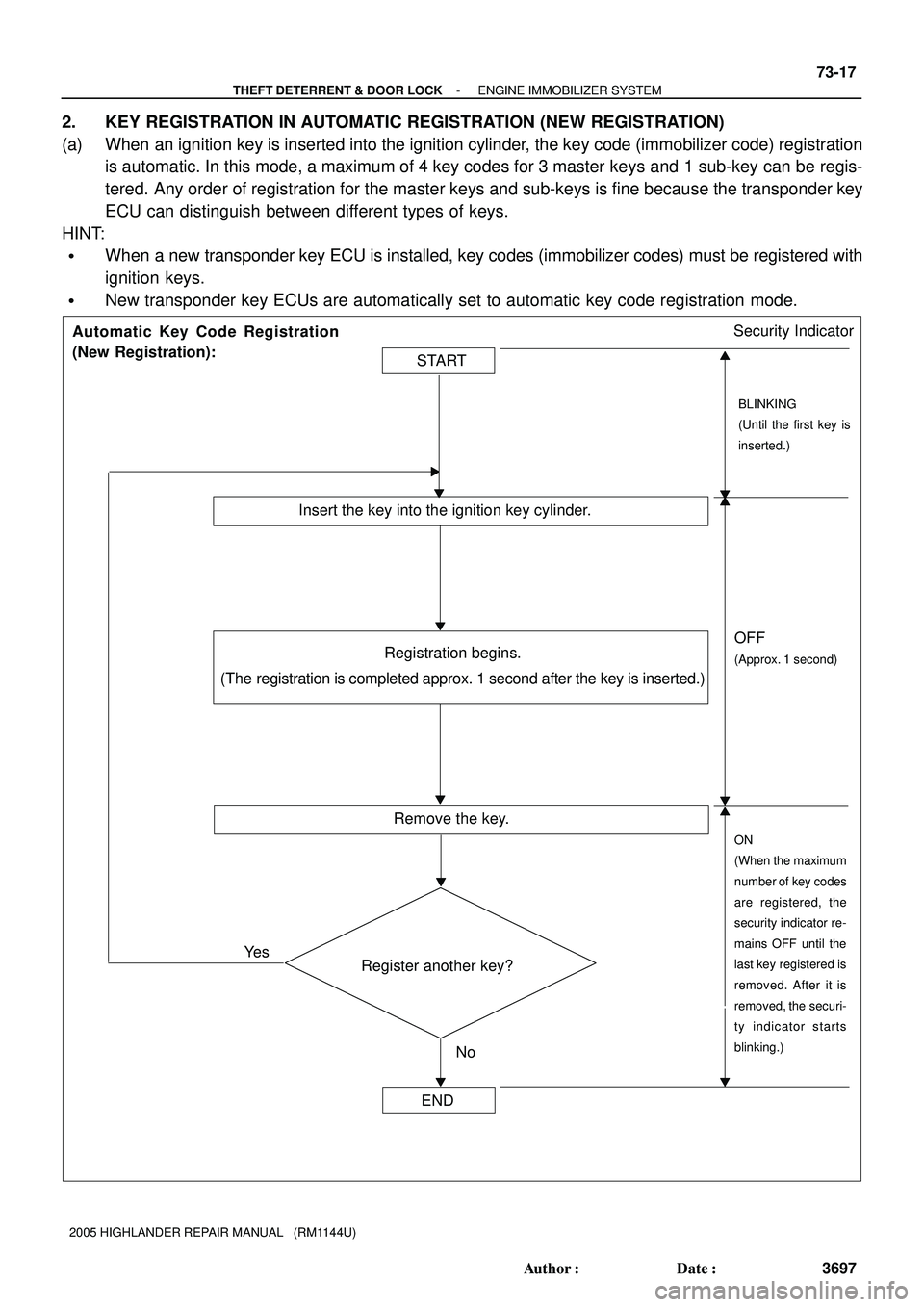
2. KEY REGISTRATION IN AUTOMATIC REGISTRATION (NEW REGISTRATION)
(a) When an ignition key is inserted into the ignition cylinder, the key code (immobilizer code) registration
is automatic. In this mode, a maximum of 4 key codes for 3 master keys and 1 sub-key can be regis-
tered. Any order of registration for the master keys and sub-keys is fine because the transponder key
ECU can distinguish between different types of keys.
HINT:
�When a new transponder key ECU is installed, key codes (immobilizer codes) must be registered with
ignition keys.
�New transponder key ECUs are automatically set to automatic key code registration mode.
Page 2567 of 2572

1.8 sec. 0.2 sec.
0.25 sec.
0.5 sec. 0.25 sec.
Code 2-1
Code 2-21 sec. Security Indicator:
Normal
(Immobilizer system is
operating normally.)
ON
OFF
ON
OFF ON
OFF
0.25 sec.1 sec.
0.25 sec.
0.25 sec.1 sec.
0.25 sec.
Code 2-3ON
OFF
0.5 sec.
0.5 sec.
73-18
- THEFT DETERRENT & DOOR LOCKENGINE IMMOBILIZER SYSTEM
3698 Author�: Date�:
2005 HIGHLANDER REPAIR MANUAL (RM1144U)
HINT:
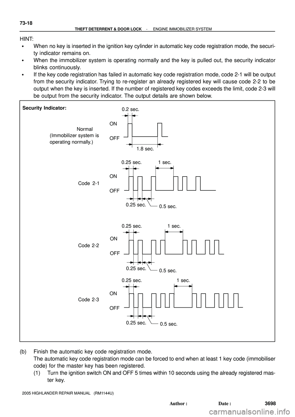
�When no key is inserted in the ignition key cylinder in automatic key code registration mode, the securi-
ty indicator remains on.
�When the immobilizer system is operating normally and the key is pulled out, the security indicator
blinks continuously.
�If the key code registration has failed in automatic key code registration mode, code 2-1 will be output
from the security indicator. Trying to re-register an already registered key will cause code 2-2 to be
output when the key is inserted. If the number of registered key codes exceeds the limit, code 2-3 will
be output from the security indicator. The output details are shown below.
(b) Finish the automatic key code registration mode.
The automatic key code registration mode can be forced to end when at least 1 key code (immobiliser
code) for the master key has been registered.
(1) Turn the ignition switch ON and OFF 5 times within 10 seconds using the already registered mas-
ter key.