Page 653 of 1897
W04200
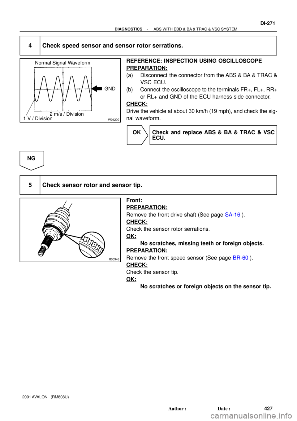
Normal Signal Waveform
2 m/s / DivisionGND
1 V / Division
R00948
- DIAGNOSTICSABS WITH EBD & BA & TRAC & VSC SYSTEM
DI-271
427 Author�: Date�:
2001 AVALON (RM808U)
4 Check speed sensor and sensor rotor serrations.
REFERENCE: INSPECTION USING OSCILLOSCOPE
PREPARATION:
(a) Disconnect the connector from the ABS & BA & TRAC &
VSC ECU.
(b) Connect the oscilloscope to the terminals FR+, FL+, RR+
or RL+ and GND of the ECU harness side connector.
CHECK:
Drive the vehicle at about 30 km/h (19 mph), and check the sig-
nal waveform.
OK Check and replace ABS & BA & TRAC & VSC
ECU.
NG
5 Check sensor rotor and sensor tip.
Front:
PREPARATION:
Remove the front drive shaft (See page SA-16).
CHECK:
Check the sensor rotor serrations.
OK:
No scratches, missing teeth or foreign objects.
PREPARATION:
Remove the front speed sensor (See page BR-60).
CHECK:
Check the sensor tip.
OK:
No scratches or foreign objects on the sensor tip.
Page 654 of 1897
R00947
DI-272
- DIAGNOSTICSABS WITH EBD & BA & TRAC & VSC SYSTEM
428 Author�: Date�:
2001 AVALON (RM808U)
Rear:
PREPARATION:
Remove the axle hub (See page SA-45).
CHECK:
Check the sensor rotor serrations.
OK:
No scratches, missing teeth or foreign objects.
PREPARATION:
Remove the rear speed sensor (See page BR-63).
CHECK:
Check the sensor tip.
OK:
No scratches or foreign objects on the sensor tip.
NG Replace sensor rotor or speed sensor.
NOTICE:
Check the speed sensor signal last (See page DI-252).
OK
Check and replace ABS & BA & TRAC & VSC
ECU.
Page 667 of 1897
F09813
Deceleration Sensor
IGA
GNDA
GL1(Shielded)
34
18YGNA
GL1 YIGA
A2078 13
AR
A20
A20ABS & BA & TRAC
& VSC ECU
(Shielded)
W
G ID1
14
ID1
16
ID1
15
ID1 BRBR-W
BR
BR3
Y1
6
Y1
5
Y1
IG
J4
J/CAR
W
G
BR-W
- DIAGNOSTICSABS WITH EBD & BA & TRAC & VSC SYSTEM
DI-285
441 Author�: Date�:
2001 AVALON (RM808U)
DTC C0365 / 43 Deceleration Sensor Circuit
CIRCUIT DESCRIPTION
Deceleration sensor is combined with yaw rate sensor.
DTC No.DTC Detecting ConditionTrouble Area
C0365 / 43
Detection of any of conditions from 1. through 4.:
1. The sensor signal is out of range, less than 0.25 V or
more than 4.75 V.
2. Deceleration difference between sensor signal and refer-
ence value is large.
3. Offset value of sensor signal is higher than the standard
value.
4. sensor signal change rapidly higher than the value at the
normal condition.
�Deceleration sensor
�Deceleration sensor circuit
WIRING DIAGRAM
DI6O1-03
Page 668 of 1897

INSPECTION PROCEDURE
HINT:
Start the inspection from step 1 in case of using the TOYOTA hand-held t")
DI-286
- DIAGNOSTICSABS WITH EBD & BA & TRAC & VSC SYSTEM
442 Author�: Date�:
2001 AVALON (RM808U)
INSPECTION PROCEDURE
HINT:
Start the inspection from step 1 in case of using the TOYOTA hand-held tester and start from step 2 in case
of not using the TOYOTA hand-held tester.
1 Check output value of the deceleration sensor.
PREPARATION:
(a) Connect the TOYOTA hand-held tester to the DLC3.
(b) Turn the ignition switch ON and push the TOYOTA hand-held tester main switch ON.
(c) Select the DATALIST mode on the TOYOTA hand-held tester.
CHECK:
Check that the deceleration value of the deceleration sensor displayed on the TOYOTA hand-held tester
is changing when tilting the vehicle.
OK:
Deceleration value must be changing.
OK Check and replace ABS & BA & TRAC & VSC
ECU.
NG
2 Check deceleration sensor (See page DI-252).
NG Replace deceleration sensor.
OK
3 Check for open or short circuit in harness and connector between deceleration
sensor and ABS & BA & TRAC & VSC ECU (See page IN-30).
NG Repair or replace harness and connector.
OK
Check and replace ABS & BA & TRAC & VSC
ECU.
Page 669 of 1897
F09813
Yaw Rate Sensor
YD
GYW2
YAW 2(Shielded)
75
77GYAW
YAWYD
A2076 1
ABR
A20
A20ABS & BA & TRAC
& VSC ECU
(Shielded)
Y
L BR
Y
LID1
2
ID1
12
ID1
15
ID1 BR
BR-W
BR
BR2
Y1
1
Y1
4
Y1
IGJ4
J/C
ABR-W
- DIAGNOSTICSABS WITH EBD & BA & TRAC & VSC SYSTEM
DI-287
443 Author�: Date�:
2001 AVALON (RM808U)
DTC C0371 / 55 Yaw Rate Sensor Circuit
CIRCUIT DESCRIPTION
DTC No.DTC Detecting ConditionTrouble Area
C0371 / 55
Detection of any of conditions from 1. through 4.:
1. The voltage of sensor signal is out of range.
2. The offset value of sensor signal is outside the plausible
range.
3. Sensor signal change rapidly under normal driving.
4. Sensor is more or worse sensitivity than reference yaw
rate during cornering.
�Yaw rate sensor
�Yaw rate sensor circuit
WIRING DIAGRAM
DI6O2-03
Page 670 of 1897

INSPECTION PROCEDURE
HINT:
Start the inspection from step 1 in case of using the TOYOTA hand")
F07893
DI-288
- DIAGNOSTICSABS WITH EBD & BA & TRAC & VSC SYSTEM
444 Author�: Date�:
2001 AVALON (RM808U)
INSPECTION PROCEDURE
HINT:
Start the inspection from step 1 in case of using the TOYOTA hand-held tester and start from step 2 in case
of not using the TOYOTA hand-held tester.
1 Check output value of the yaw rate sensor.
PREPARATION:
(a) Remove the 2 bolts and yaw rate sensor with connector
still connected.
(b) Connect the TOYOTA hand-held tester to the DLC3.
(c) Turn the ignition switch ON and push the TOYOTA hand-
held tester main switch ON.
(d) Select the DATALIST mode on the TOYOTA hand-held
tester.
CHECK:
Check that the yaw rate value of the yaw rate sensor displayed
on the TOYOTA hand-held tester is changing: Place the yaw
rate sensor vertically to the ground and turn the sensor pivoted
on its center.
OK:
Yaw rate value must be changing.
OK Go to step 3.
NG
2 Check whether continuity exists between terminal YD of yaw rate sensor and ter-
minal YD of ABS & BA & TRAC & VSC ECU.
NG Repair or replace harness or connector.
OK
Check and replace ABS & BA & TRAC & VSC
ECU.
Page 671 of 1897
F09478
1
3
4
1
2
- DIAGNOSTICSABS WITH EBD & BA & TRAC & VSC SYSTEM
DI-289
445 Author�: Date�:
2001 AVALON (RM808U)
3 Check yaw rate sensor.
CHECK:
(a) Turn the ignition switch ON.
(b) Measure the voltage between terminals IGA (3) and
GYW2 (1), YAW2 (4) and GYW2 (1) of the yaw rate sensor
with connector still connected.
OK:
Terminals 3 and 1
(IGA - GYW2)Approx. 12 V
Terminals 4 and 1
(YAW2 - GYW2)Approx. 2.5 V
NG Replace yaw rate sensor.
OK
4 Check for open and short circuit in harness and connector between yaw rate
sensor and ABS & BA & TRAC & VSC ECU (See page IN-30).
NG Repair or replace harness or connector.
OK
Check and replace ABS & BA & TRAC & VSC
ECU.
Page 674 of 1897
5
48
7 C11
Steering
Sensor
W-B R-B19 6
77
3B 3A 3A
3A(Shielded)
59
61
60
2 ABS & BA &
TRAC & VSC ECU
SS1
SS2")
F09819
Translate ECU
SS2 SS1 RSS VSC- VSC+ T5
T5
T5
T5
T54
5
18 17
6W
O
BR
L
B-W
(Shielded)5
48
7 C11
Steering
Sensor
W-B R-B19 6
77
3B 3A 3A
3A(Shielded)
59
61
60
2 ABS & BA &
TRAC & VSC ECU
SS1
SS2
FSS
R+ A20
BR
GR-R
W-B
A
AJ5
J/C
W-B
IG J/B No. 3A20
A20
A20 DI-292
- DIAGNOSTICSABS WITH EBD & BA & TRAC & VSC SYSTEM
448 Author�: Date�:
DTC C1208 / 54 Steering Angle Sensor Circuit
CIRCUIT DESCRIPTION
DTC No.DTC Detecting ConditionTrouble Area
C1208 / 54
Detection of any of conditions 1. through 7:
1. When the condition that ECU terminal IG1 voltage is 9.8
v or more, and does not receive data from steering angle
sensor continues for 0.1 sec. or more.
2. Sensor internal failure.
3. The offset value is out of range.
4. Sensor signal change higher.
5. Steering angle value difference between measured and
reference is out of range.
6. Steering sensor is not centered.
7. Steering sensor signal is out of range.
�Steering angle sensor
�Steering angle sensor circuit
WIRING DIAGRAM
DI6O4-01


34
18YGNA
GL1 YIGA
A2078 13
AR
A20
A20ABS & BA & TRAC
& VSC ECU
(Shielded)
W
G ID1
14
ID1
16
ID1
15
ID1 BRBR-W
BR
BR3
Y1
6
Y1
5
Y1
IG
J4
J/CAR
W
G
BR-")

75
77GYAW
YAWYD
A2076 1
ABR
A20
A20ABS & BA & TRAC
& VSC ECU
(Shielded)
Y
L BR
Y
LID1
2
ID1
12
ID1
15
ID1 BR
BR-W
BR
BR2
Y1
1
Y1
4
Y1
IGJ4
J/C
ABR-W
- DI")