Page 1343 of 1897
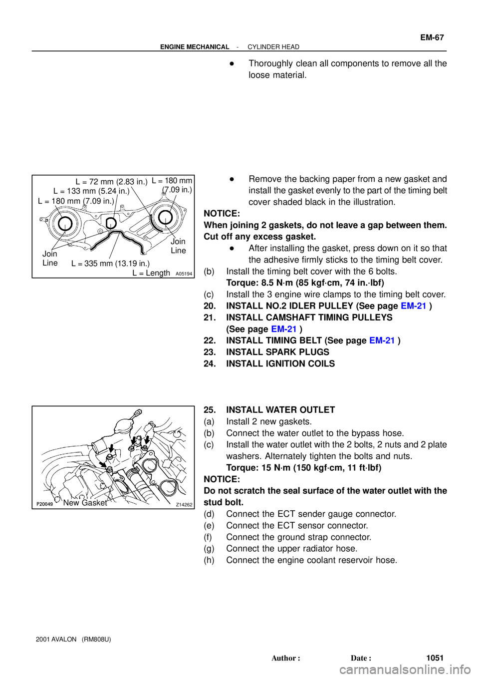
A05194
L = 133 mm (5.24 in.)
L = 180 mm (7.09 in.)L = 72 mm (2.83 in.)
L = 335 mm (13.19 in.)L = 180 mm
(7.09 in.)
L = Length Join
LineJoin
Line
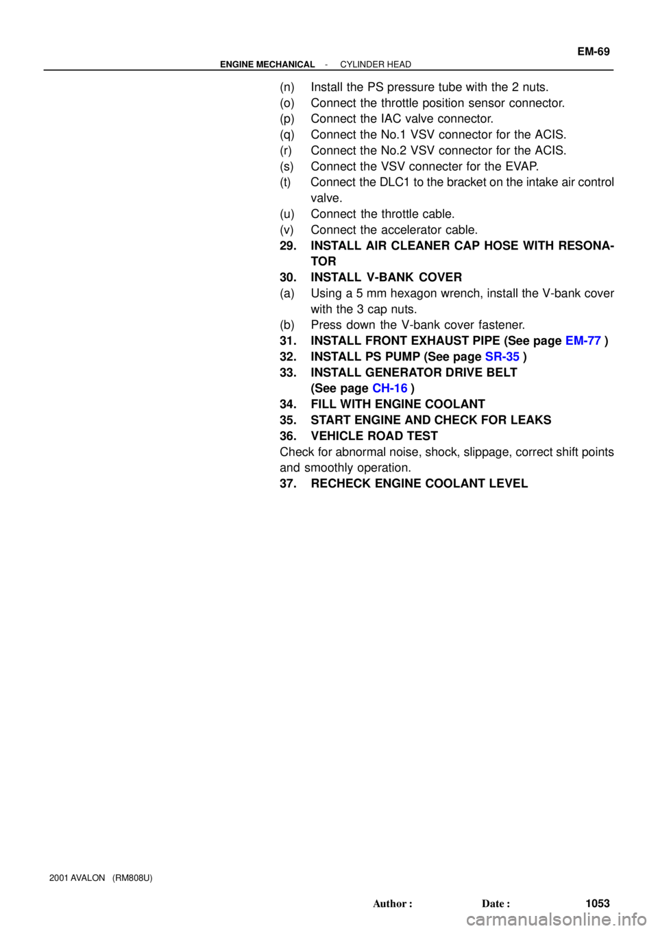
Z14262New Gasket
- ENGINE MECHANICALCYLINDER HEAD
EM-67
1051 Author�: Date�:
2001 AVALON (RM808U)
�Thoroughly clean all components to remove all the
loose material.
�Remove the backing paper from a new gasket and
install the gasket evenly to the part of the timing belt
cover shaded black in the illustration.
NOTICE:
When joining 2 gaskets, do not leave a gap between them.
Cut off any excess gasket.
�After installing the gasket, press down on it so that
the adhesive firmly sticks to the timing belt cover.
(b) Install the timing belt cover with the 6 bolts.
Torque: 8.5 N´m (85 kgf´cm, 74 in.´lbf)
(c) Install the 3 engine wire clamps to the timing belt cover.
20. INSTALL NO.2 IDLER PULLEY (See page EM-21)
21. INSTALL CAMSHAFT TIMING PULLEYS
(See page EM-21)
22. INSTALL TIMING BELT (See page EM-21)
23. INSTALL SPARK PLUGS
24. INSTALL IGNITION COILS
25. INSTALL WATER OUTLET
(a) Install 2 new gaskets.
(b) Connect the water outlet to the bypass hose.
(c) Install the water outlet with the 2 bolts, 2 nuts and 2 plate
washers. Alternately tighten the bolts and nuts.
Torque: 15 N´m (150 kgf´cm, 11 ft´lbf)
NOTICE:
Do not scratch the seal surface of the water outlet with the
stud bolt.
(d) Connect the ECT sender gauge connector.
(e) Connect the ECT sensor connector.
(f) Connect the ground strap connector.
(g) Connect the upper radiator hose.
(h) Connect the engine coolant reservoir hose.
Page 1345 of 1897
- ENGINE MECHANICALCYLINDER HEAD
EM-69
1053 Author�: Date�:
2001 AVALON (RM808U)
(n) Install the PS pressure tube with the 2 nuts.
(o) Connect the throttle position sensor connector.
(p) Connect the IAC valve connector.
(q) Connect the No.1 VSV connector for the ACIS.
(r) Connect the No.2 VSV connector for the ACIS.
(s) Connect the VSV connecter for the EVAP.
(t) Connect the DLC1 to the bracket on the intake air control
valve.
(u) Connect the throttle cable.
(v) Connect the accelerator cable.
29. INSTALL AIR CLEANER CAP HOSE WITH RESONA-
TOR
30. INSTALL V-BANK COVER
(a) Using a 5 mm hexagon wrench, install the V-bank cover
with the 3 cap nuts.
(b) Press down the V-bank cover fastener.
31. INSTALL FRONT EXHAUST PIPE (See page EM-77)
32. INSTALL PS PUMP (See page SR-35)
33. INSTALL GENERATOR DRIVE BELT
(See page CH-16)
34. FILL WITH ENGINE COOLANT
35. START ENGINE AND CHECK FOR LEAKS
36. VEHICLE ROAD TEST
Check for abnormal noise, shock, slippage, correct shift points
and smoothly operation.
37. RECHECK ENGINE COOLANT LEVEL
Page 1349 of 1897
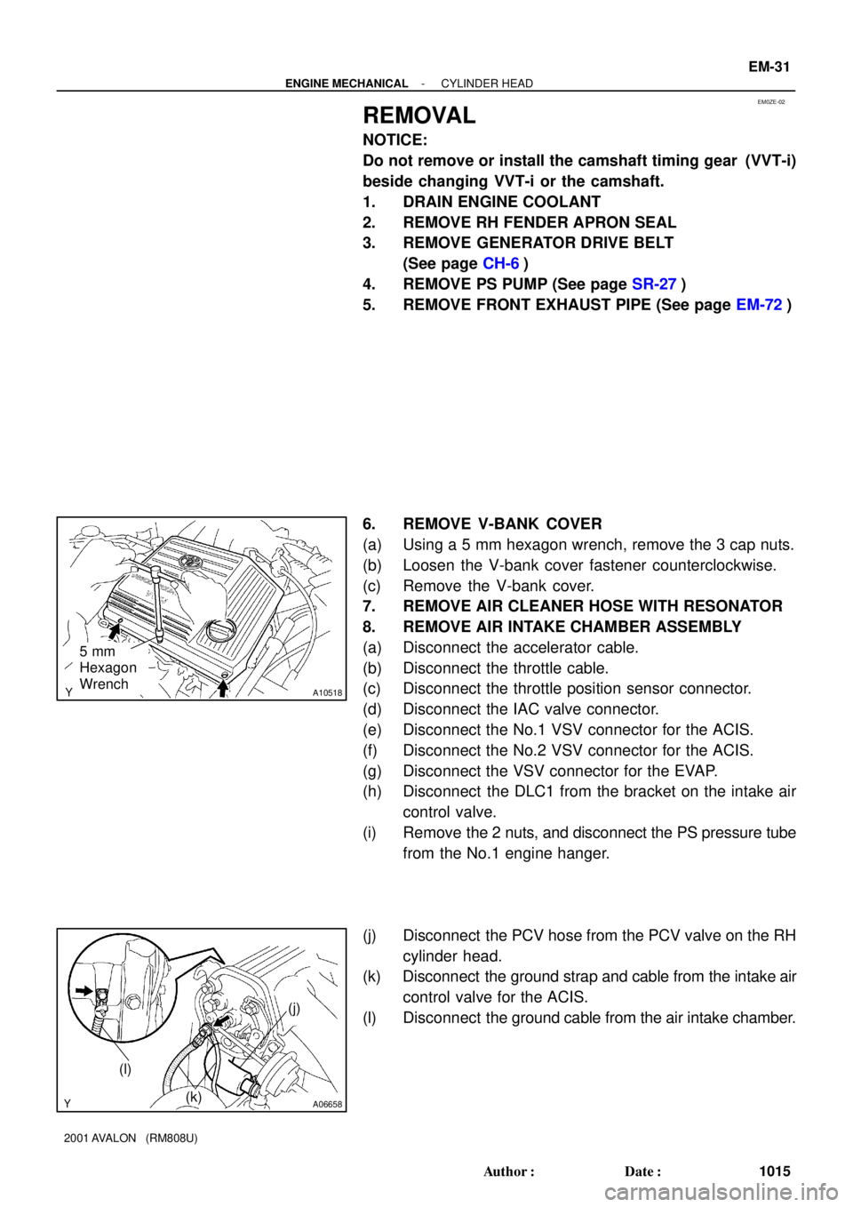
EM0ZE-02
A10518
5 mm
Hexagon
Wrench
A06658
(j)
(k) (l)
- ENGINE MECHANICALCYLINDER HEAD
EM-31
1015 Author�: Date�:
2001 AVALON (RM808U)
REMOVAL
NOTICE:
Do not remove or install the camshaft timing gear (VVT-i)
beside changing VVT-i or the camshaft.
1. DRAIN ENGINE COOLANT
2. REMOVE RH FENDER APRON SEAL
3. REMOVE GENERATOR DRIVE BELT
(See page CH-6)
4. REMOVE PS PUMP (See page SR-27)
5. REMOVE FRONT EXHAUST PIPE (See page EM-72)
6. REMOVE V-BANK COVER
(a) Using a 5 mm hexagon wrench, remove the 3 cap nuts.
(b) Loosen the V-bank cover fastener counterclockwise.
(c) Remove the V-bank cover.
7. REMOVE AIR CLEANER HOSE WITH RESONATOR
8. REMOVE AIR INTAKE CHAMBER ASSEMBLY
(a) Disconnect the accelerator cable.
(b) Disconnect the throttle cable.
(c) Disconnect the throttle position sensor connector.
(d) Disconnect the IAC valve connector.
(e) Disconnect the No.1 VSV connector for the ACIS.
(f) Disconnect the No.2 VSV connector for the ACIS.
(g) Disconnect the VSV connector for the EVAP.
(h) Disconnect the DLC1 from the bracket on the intake air
control valve.
(i) Remove the 2 nuts, and disconnect the PS pressure tube
from the No.1 engine hanger.
(j) Disconnect the PCV hose from the PCV valve on the RH
cylinder head.
(k) Disconnect the ground strap and cable from the intake air
control valve for the ACIS.
(l) Disconnect the ground cable from the air intake chamber.
Page 1351 of 1897

A07428
P20049Gasket
A05077
Clamp
Clamp
Clamp
A10531
- ENGINE MECHANICALCYLINDER HEAD
EM-33
1017 Author�: Date�:
2001 AVALON (RM808U)
(d) Remove the 9 bolts, 2 nuts, 2 plate washers, the intake
manifold, delivery pipes and injectors assembly.
NOTICE:
�Be careful not to drop the injectors when removing
the delivery pipes.
�Pay attention to put any hung load on the injector to
and from the side direction.
10. REMOVE WATER OUTLET
(a) Disconnect the ECT sender gauge connector.
(b) Disconnect the ECT sensor connector.
(c) Disconnect the ground strap connector.
(d) Disconnect the upper radiator hose.
(e) Disconnect the engine coolant reservoir hose.
(f) Remove the 2 bolts, 2 nuts and 2 plate washers.
(g) Disconnect the water bypass hose, and remove the water
outlet.
(h) Remove the 2 gaskets.
11. REMOVE IGNITION COILS
12. REMOVE SPARK PLUGS
13. REMOVE TIMING BELT (See page EM-15)
14. REMOVE CAMSHAFT TIMING PULLEYS
(See page EM-15)
15. REMOVE NO.2 IDLER PULLEY (See page EM-15)
16. REMOVE NO.3 TIMING BELT COVER
(a) Disconnect the 3 engine wire clamps from the timing belt
cover.
(b) Remove the 6 bolts and timing belt cover.
17. REMOVE CAMSHAFT POSITION SENSORS
18. REMOVE CAMSHAFT TIMING OIL CONTROL VALVES
19. DISCONNECT ENGINE WIRE PROTECTOR FROM
REAR SIDE
Remove the nut, and disconnect the engine wire protector from
the RH cylinder head.
Page 1367 of 1897
S04497
A07300
- ENGINE MECHANICALENGINE UNIT
EM-79
1063 Author�: Date�:
2001 AVALON (RM808U)
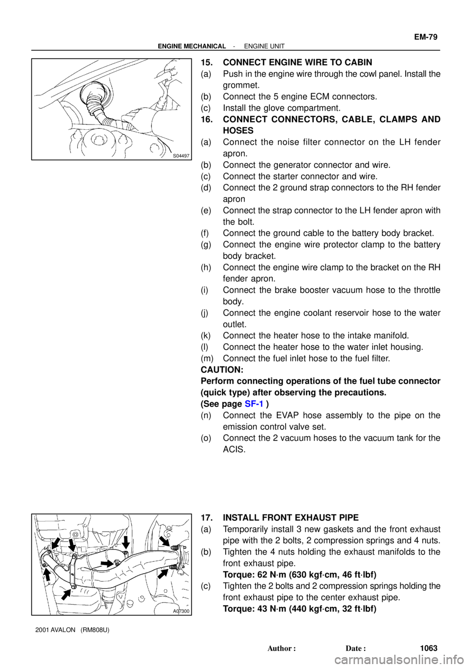
15. CONNECT ENGINE WIRE TO CABIN
(a) Push in the engine wire through the cowl panel. Install the
grommet.
(b) Connect the 5 engine ECM connectors.
(c) Install the glove compartment.
16. CONNECT CONNECTORS, CABLE, CLAMPS AND
HOSES
(a) Connect the noise filter connector on the LH fender
apron.
(b) Connect the generator connector and wire.
(c) Connect the starter connector and wire.
(d) Connect the 2 ground strap connectors to the RH fender
apron
(e) Connect the strap connector to the LH fender apron with
the bolt.
(f) Connect the ground cable to the battery body bracket.
(g) Connect the engine wire protector clamp to the battery
body bracket.
(h) Connect the engine wire clamp to the bracket on the RH
fender apron.
(i) Connect the brake booster vacuum hose to the throttle
body.
(j) Connect the engine coolant reservoir hose to the water
outlet.
(k) Connect the heater hose to the intake manifold.
(l) Connect the heater hose to the water inlet housing.
(m) Connect the fuel inlet hose to the fuel filter.
CAUTION:
Perform connecting operations of the fuel tube connector
(quick type) after observing the precautions.
(See page SF-1)
(n) Connect the EVAP hose assembly to the pipe on the
emission control valve set.
(o) Connect the 2 vacuum hoses to the vacuum tank for the
ACIS.
17. INSTALL FRONT EXHAUST PIPE
(a) Temporarily install 3 new gaskets and the front exhaust
pipe with the 2 bolts, 2 compression springs and 4 nuts.
(b) Tighten the 4 nuts holding the exhaust manifolds to the
front exhaust pipe.
Torque: 62 N´m (630 kgf´cm, 46 ft´lbf)
(c) Tighten the 2 bolts and 2 compression springs holding the
front exhaust pipe to the center exhaust pipe.
Torque: 43 N´m (440 kgf´cm, 32 ft´lbf)
Page 1368 of 1897
EM-80
- ENGINE MECHANICALENGINE UNIT
1064 Author�: Date�:
2001 AVALON (RM808U)
(d) Install the support stay with the 2 bolts.
Torque: 33 N´m (330 kgf´cm, 24 ft´lbf)
18. INSTALL RADIATOR (See page CO-22)
19. INSTALL CRUISE CONTROL ACTUATOR
20. INSTALL AIR CLEANER CAP ASSEMBLY AND AIR
CLEANER CASE
21. CONNECT ACCELERATOR CABLE
22. INSTALL V-BANK COVER
(a) Using a 5 mm hexagon wrench, install the V-bank cover
with the 3 cap nuts.
(b) Press down the V-bank cover fastener.
23. INSTALL ENGINE FENDER APRON SEALS
24. INSTALL BATTERY TRAY AND BATTERY
25. INSTALL HOOD
26. FILL ENGINE WITH OIL
27. FILL WITH ENGINE COOLANT
28. START ENGINE AND CHECK FOR LEAKS
29. PERFORM ROAD TEST
Check for abnormal noise, shock, slippage, correct shift points
and smooth operation.
30. RECHECK ENGINE COOLANT AND OIL LEVELS
Page 1369 of 1897
EM0ZL-02
A10518
5 mm
Hexagon
Wrench
A07300
EM-72
- ENGINE MECHANICALENGINE UNIT
1056 Author�: Date�:
2001 AVALON (RM808U)
REMOVAL
1. REMOVE BATTERY AND TRAY
2. REMOVE HOOD
3. REMOVE ENGINE FENDER APRON SEALS
4. DRAIN ENGINE COOLANT
5. DRAIN ENGINE OIL
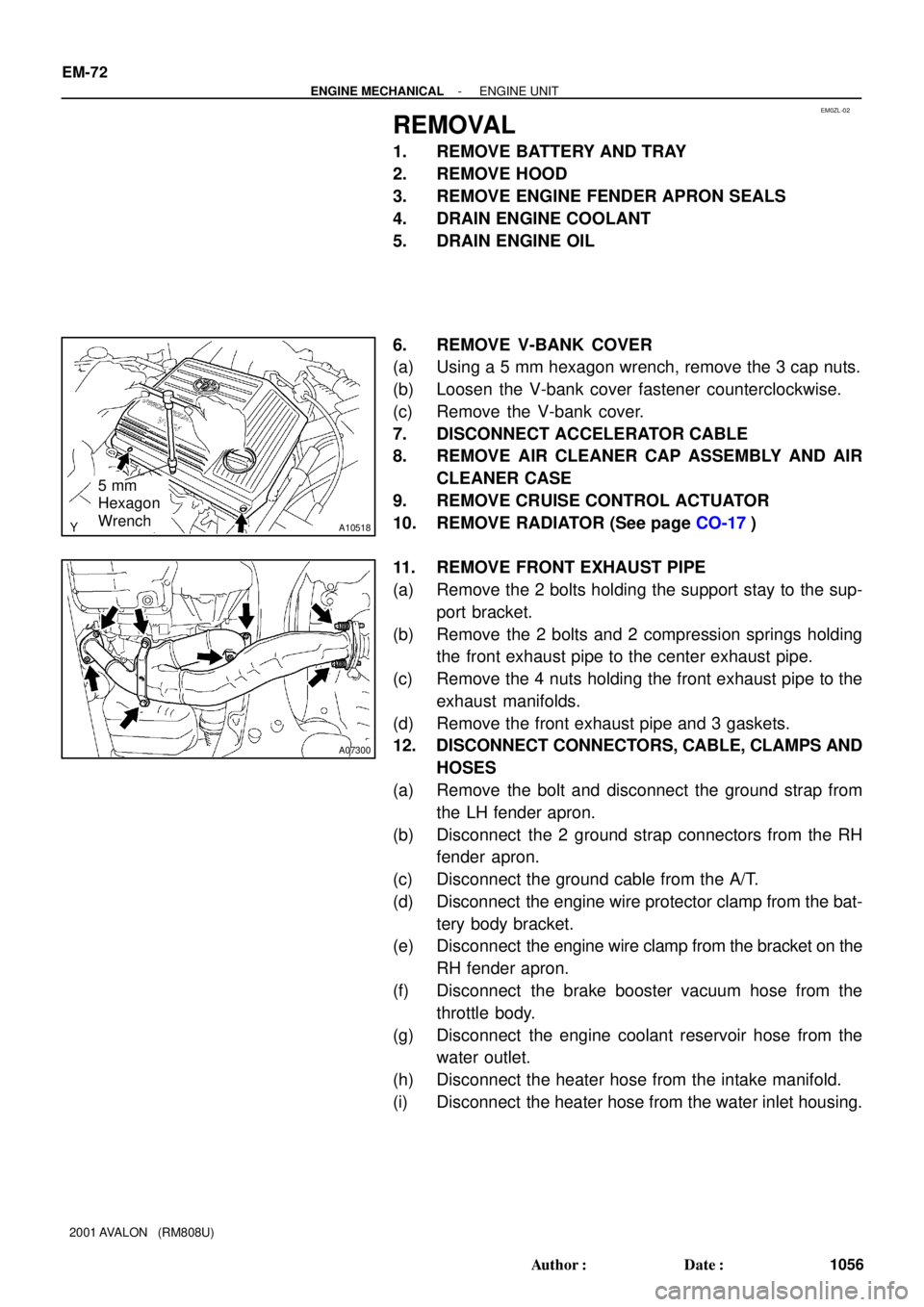
6. REMOVE V-BANK COVER
(a) Using a 5 mm hexagon wrench, remove the 3 cap nuts.
(b) Loosen the V-bank cover fastener counterclockwise.
(c) Remove the V-bank cover.
7. DISCONNECT ACCELERATOR CABLE
8. REMOVE AIR CLEANER CAP ASSEMBLY AND AIR
CLEANER CASE
9. REMOVE CRUISE CONTROL ACTUATOR
10. REMOVE RADIATOR (See page CO-17)
11. REMOVE FRONT EXHAUST PIPE
(a) Remove the 2 bolts holding the support stay to the sup-
port bracket.
(b) Remove the 2 bolts and 2 compression springs holding
the front exhaust pipe to the center exhaust pipe.
(c) Remove the 4 nuts holding the front exhaust pipe to the
exhaust manifolds.
(d) Remove the front exhaust pipe and 3 gaskets.
12. DISCONNECT CONNECTORS, CABLE, CLAMPS AND
HOSES
(a) Remove the bolt and disconnect the ground strap from
the LH fender apron.
(b) Disconnect the 2 ground strap connectors from the RH
fender apron.
(c) Disconnect the ground cable from the A/T.
(d) Disconnect the engine wire protector clamp from the bat-
tery body bracket.
(e) Disconnect the engine wire clamp from the bracket on the
RH fender apron.
(f) Disconnect the brake booster vacuum hose from the
throttle body.
(g) Disconnect the engine coolant reservoir hose from the
water outlet.
(h) Disconnect the heater hose from the intake manifold.
(i) Disconnect the heater hose from the water inlet housing.
Page 1377 of 1897
EM03Y-03
A10834
RH Fender Apron Seal
Generator Drive Belt
Engine Moving
Control Rod
No.2 RH Engine
Mounting Bracket
Ground Strap
Connector PS Pump Drive Belt
Engine Coolant Reservoir Hose
: Specified torque
64 (650, 47)
32 (320, 23)
N´m (kgf´cm, ft´lbf)
- ENGINE MECHANICALTIMING BELT
EM-13
997 Author�: Date�:
2001 AVALON (RM808U)
TIMING BELT
COMPONENTS