Page 858 of 1897
 (+)
- DIAGNOSTICSCRUIS")
Input SignalIndicator Light
Blinking Pattern
SET/COAST
switch
RESUME/ACCEL
switch
CANCEL switch2 Pulses
ON
OFF
ON
OFF3 Pulses
ON
OFFSW OFF
SW ON
AB0119
I00168
I00171
ON
CCS
(-) (+)
- DIAGNOSTICSCRUISE CONTROL SYSTEM
DI-573
729 Author�: Date�:
2001 AVALON (RM808U)
INSPECTION PROCEDURE
1 Input signal check.
PREPARATION:
See input signal check on page DI-551.
CHECK:
Check the indicator light operation when each of the SET/
COAST, RESUME/ACCEL and CANCEL is turned on.
OK:
SET/COAST, RESUME/ACCEL switch
The signals shown in the table on the left should be
output when each switch is ON. The signal should
disappear when the switch is turned OFF.
CANCEL switch
The indicator light goes off when the cancel switch is
turned ON.
OK Wait and see.
NG
2 Check voltage between terminals CCS of cruise control ECU connector and body
ground.
PREPARATION:
(a) Remove the ECU with connector still connected.
(b) Turn ignition switch ON.
CHECK:
Measure voltage between terminals 18 of ECU connector and
body ground, when each of the SET/COAST, RESUME/AC-
CEL and CANCEL is turned ON.
Switch positionResistance (V)
Neutral10 - 16 V
MAINBelow 1V
REST/ACC4.7 - 7.7 V
SET/COAST2.6 - 4.2 V
NG Proceed to next circuit inspection shown in
problem symptom table (See page DI-560)
OK
Page 866 of 1897
I13610
Cruise Control ECU
4
PI
R-B
W-B10
1D
IF17W-R
4 IG1 AM1Ignition Switch 2
W
AM1 GAUGE NO. 1
2 1
5
B-L1
ALTFL Block
1 B
FL MAIN
BatteryF8 2G1
F6 F10
1
1
2H
B 5
W-LW-L 1
43 3
1B1
1G
4
1C IG1 RERAY 4
4D13
4F4
M7 M64
4H17
4A17
GR-R
R-BGR-R Cruise Control
Indicator Light
(in Multi Display)
IG
C15
I15
2J/B No. 4 J/B No. 4
Driver Side J/B
Engine Room R/B No. 5
Engine Room J/B DI-592
- DIAGNOSTICSCRUISE CONTROL SYSTEM
748 Author�: Date�:
2001 AVALON (RM808U)
CRUISE MAIN Indicator Light Circuit
CIRCUIT DESCRIPTION
When the cruise control main switch is turned ON, CRUISE MAIN indicator light lights up.
WIRING DIAGRAM
DI090-28
Page 876 of 1897
I17550
Cruise Control ECU
D 3
W-B 2
Ignition Switch1 II1
1G
3
4 4
2 1C
1
F10
1
ALT FL Block
1
FL MAINBattery IG1AM1CCS
F6 F8W-L26
1 20
AM1 Y-RY-R
R-L
R-LR-L
R-Y23
3D20
3C20
3C7
R-LY-R 4C6
4C19
II14
10 DL 2
W-R W
4
27
IF15
5 2
1
1 1
2H
2G
B-L1C1
1B3
IG B IG1 Relay
GAUGE NO. 2 A/T Indicator Light
Translate ECU
*1: w/ Traction Control
*2: w/o Tranction Control*1*2
T5
P1C15
I15
W-L
D6
DiodeY-R
*3: Floor Shift
*4: Column ShiftJ/B No. 4
J/B No. 3
*4
*3
Driver Side J/B
Engine Room R/B No. 5
BEngine Room J/B DI-584
- DIAGNOSTICSCRUISE CONTROL SYSTEM
740 Author�: Date�:
2001 AVALON (RM808U)
Park/Neutral Position Switch Circuit
CIRCUIT DESCRIPTION
When the shift position is except D, a signal is sent from the park/neutral position switch to the ECU. When
this signal is input during cruise control driving, the ECU cancels the cruise control.
WIRING DIAGRAM
DI08V-15
Page 877 of 1897
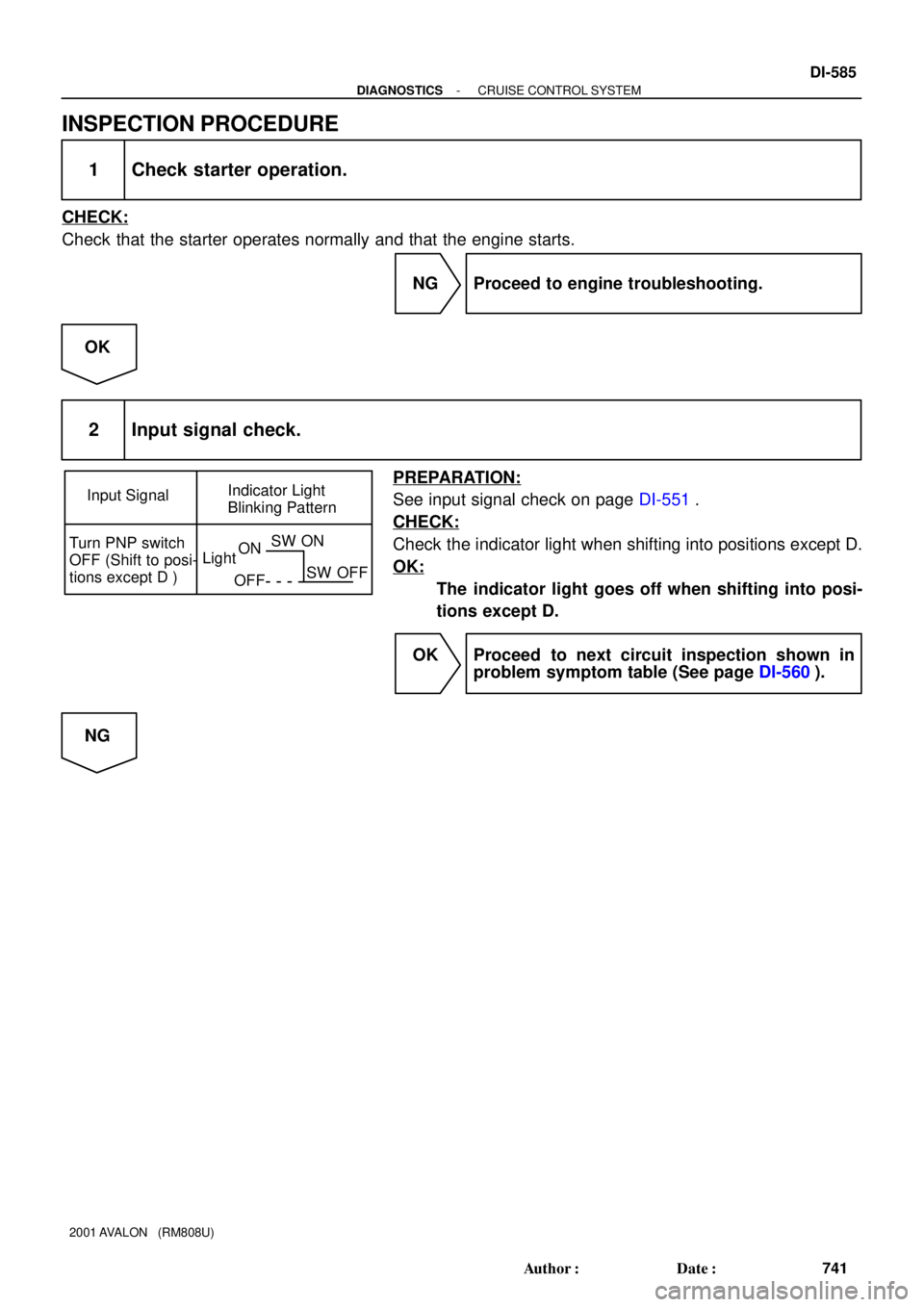
Input SignalIndicator Light
Blinking Pattern
Turn PNP switch
OFF (Shift to posi-
tions except D )LightON
OFFSW ON
SW OFF
- DIAGNOSTICSCRUISE CONTROL SYSTEM
DI-585
741 Author�: Date�:
2001 AVALON (RM808U)
INSPECTION PROCEDURE
1 Check starter operation.
CHECK:
Check that the starter operates normally and that the engine starts.
NG Proceed to engine troubleshooting.
OK
2 Input signal check.
PREPARATION:
See input signal check on page DI-551.
CHECK:
Check the indicator light when shifting into positions except D.
OK:
The indicator light goes off when shifting into posi-
tions except D.
OK Proceed to next circuit inspection shown in
problem symptom table (See page DI-560).
NG
Page 879 of 1897

I13608
Cruise Control ECU
2
STP
G-W
R3
3C 1B
1
4Stop Light Switch
2
95
FL BlockC15
C15 3
II1
BatterySTOP
W
B 1D33
3D
P-B
W-B
IJ AJ9 J/C W-BP-BG-B8
L F61
F101
ALT
FL MAIN1D11
1G1
II1 13
43
C4
Cruise Control Actuator
S4 Stop Light Switch
S4J/B No. 3
Driver Side J/B Driver Side J/B
G-W
G-W DI-578
- DIAGNOSTICSCRUISE CONTROL SYSTEM
734 Author�: Date�:
2001 AVALON (RM808U)
Stop Light Switch Circuit
CIRCUIT DESCRIPTION
When the brake pedal is depressed, the stop light switch sends a signal to the ECU. When the ECU receives
this signal, it cancels the cruise control.
A fail-safe function is provided so that the cancel functions normally, even if there is a malfunction in the stop
light signal circuit.
The cancel conditions are: Battery positive voltage at terminal STP-
When the brake is ON, battery positive voltage normally is applied through the STOP fuse and stop light
switch to terminal STP- of the ECU, and the ECU turns the cruise control OFF.
If the harness connected to terminal STP- has an open circuit, terminal STP- will have battery positive volt-
age and the cruise control will be turned OFF.
Also, when the brake is ON, the magnetic clutch circuit is cut mechanically by the stop light switch, turning
the cruise control OFF. (See page DI-563 for operation of the magnetic clutch)
WIRING DIAGRAM
DI08T-17
Page 880 of 1897
Input SignalIndicator Light
Blinking Pattern
Stop Light
switch ON
LightOFF
ONSW OFF
SW ON
- DIAGNOSTICSCRUISE CONTROL SYSTEM
DI-579
735 Author�: Date�:
2001 AVALON (RM808U)
INSPECTION PROCEDURE
1 Check operation of stop light.
CHECK:
Check that stop light comes ON when brake pedal is depressed, and turns OFF when brake pedal is re-
leased.
NG Check stop light system (See page BE-2).
OK
2 Input signal check.
CHECK:
(a) See input signal check on DI-551.
(b) Check the indicator light when the brake pedal is de-
pressed.
OK:
The indicator light goes OFF when the brake pedal is
depressed.
OK Proceed to next circuit inspection shown in
problem symptom table (See page DI-560).
NG
Page 881 of 1897
AB0119
I00142
I00173
ON
STP-
(-) (+)
DI-580
- DIAGNOSTICSCRUISE CONTROL SYSTEM
736 Author�: Date�:
2001 AVALON (RM808U)
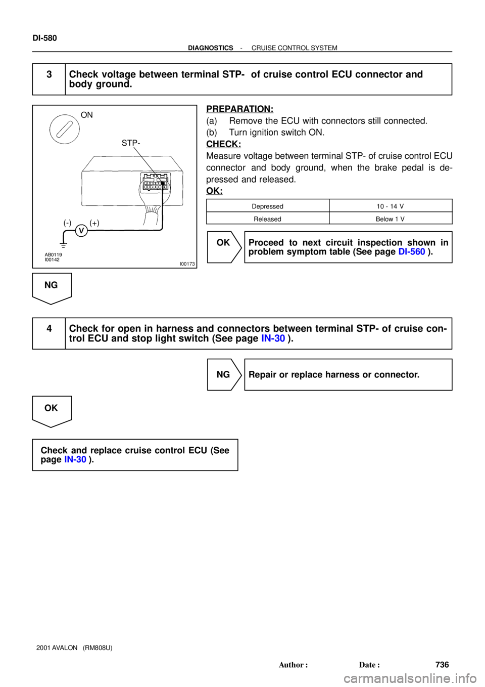
3 Check voltage between terminal STP- of cruise control ECU connector and
body ground.
PREPARATION:
(a) Remove the ECU with connectors still connected.
(b) Turn ignition switch ON.
CHECK:
Measure voltage between terminal STP- of cruise control ECU
connector and body ground, when the brake pedal is de-
pressed and released.
OK:
Depressed10 - 14 V
ReleasedBelow 1 V
OK Proceed to next circuit inspection shown in
problem symptom table (See page DI-560).
NG
4 Check for open in harness and connectors between terminal STP- of cruise con-
trol ECU and stop light switch (See page IN-30).
NG Repair or replace harness or connector.
OK
Check and replace cruise control ECU (See
page IN-30).
Page 882 of 1897

DI08G-10
CRUISE CONTROL SYSTEM Check Sheet
Inspector 's name:
Customer 's Name
Date VehicleRegistration No.
Registration Year
Frame No.
Odometer Reading / /km
Mile
Condition of
Problem Occurrence
Date of Problem
How Often does
Occurrence
Problem Occurs
Vehicle Speed when
Problem Occurred / /
Continuous Intermittent ( Times a day)
km
Mile Brought in
Auto cancel
occurs� Driving condition
� City driving � Freeway � Up hill � Down hill
� After cancel occurred, did the driver activate cruise control
again?
� Yes � No
� Cancel does not
occur� With brake ON
� Except D position shift � At 40 km/h (25 mph) or less
� When control SW turns to CANCEL position
� Cruise control
malfunction� Slip to acceleration side
� Slip to deceleration side
� Hunting occurs
� O/D cut off does not occur
� O/D does not return
� Switch
malfunction� SET � ACCEL � COAST � RESUME � CANCEL
� Cruise MAIN
indicator light� Remains ON � Does not light up � Blinking Symptoms
DTC Check1st Time2nd Time
� Normal Code � Malfunction Code (Code )
� Normal Code � Malfunction Code (Code ) DI-550
- DIAGNOSTICSCRUISE CONTROL SYSTEM
706 Author�: Date�:
2001 AVALON (RM808U)
CUSTOMER PROBLEM ANALYSIS CHECK