Page 826 of 1897
I13638
Battery FL MAIN
B 1 1
ALT
F10 F6 W111 STOP
1G 1D
R2
S4
Stop Light Switch
1
G-W3
1D11
STOP Engine Room J/BBody ECU
Engine
Room J/B DI-662
- DIAGNOSTICSBODY CONTROL SYSTEM
818 Author�: Date�:
2001 AVALON (RM808U)
Stop light switch circuit
CIRCUIT DESCRIPTION
The Body ECU is detecting the condition of the stop light switch.
WIRING DIAGRAM
DI6M0-01
Page 827 of 1897
- DIAGNOSTICSBODY CONTROL SYSTEM
DI-663
819 Author�: Date�:
2001 AVALON (RM808U)
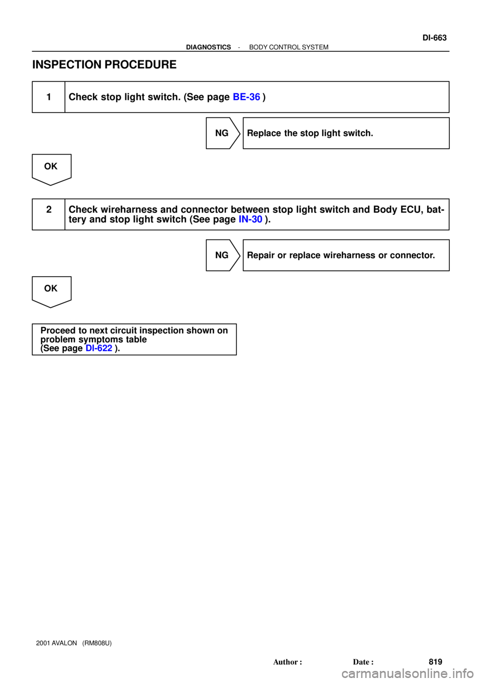
INSPECTION PROCEDURE
1 Check stop light switch. (See page BE-36)
NG Replace the stop light switch.
OK
2 Check wireharness and connector between stop light switch and Body ECU, bat-
tery and stop light switch (See page IN-30).
NG Repair or replace wireharness or connector.
OK
Proceed to next circuit inspection shown on
problem symptoms table
(See page DI-622).
Page 828 of 1897
I13646
FL Block
11
F6 F10
B
FL MAINALT
BatteryW1
1GTAIL RELAY
53
12
to Taillight9Body ECU
TRLY Driver Side J/B
- DIAGNOSTICSBODY CONTROL SYSTEM
DI-633
789 Author�: Date�:
2001 AVALON (RM808U)
Taillight relay circuit
CIRCUIT DESCRIPTION
Taillight relay will be ºONº by operating the taillight switch. The transistor which activates the tail light relay
has two sorts: one activates by the tail light switch for fail safe and the other activates by CPU.
WIRING DIAGRAM
DI6LM-01
Page 829 of 1897
DI-634
- DIAGNOSTICSBODY CONTROL SYSTEM
790 Author�: Date�:
2001 AVALON (RM808U)
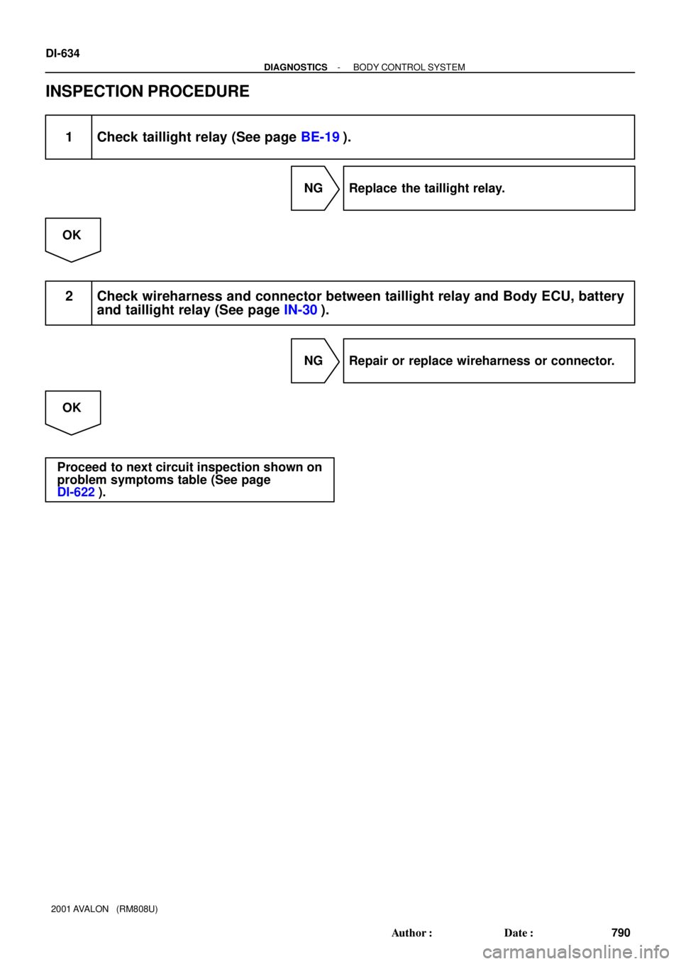
INSPECTION PROCEDURE
1 Check taillight relay (See page BE-19).
NG Replace the taillight relay.
OK
2 Check wireharness and connector between taillight relay and Body ECU, battery
and taillight relay (See page IN-30).
NG Repair or replace wireharness or connector.
OK
Proceed to next circuit inspection shown on
problem symptoms table (See page
DI-622).
Page 834 of 1897
DI6LG-01
BODY CONTROL SYSTEM Check Sheet
Inspector 's name:
Customer 's Name
Date VehicleRegistration No.
Registration Year
Frame No.
Odometer Reading / /km
Mile
Weather Conditions
When Problem
Occurred
Date Problem First Occurred
Frequency Problem Occurs
Weather
/ /
Once only Brought in
Key Unlock Warning System
Malfunction
System
Outdoor Temperature
Fine Cloudy Rainy Snowy
Various/ Others
Hot Warm Cool
Cold (Approx. °F ( °C))
Constant Sometimes ( times per day, month)
Illuminated Entry System
Seat Belt Warning
Power Window Control System
Power Door Lock Control System
Wireless Door Lock Control System
Others (Buzzer etc.)
Automatic Light Control System
Luggage Compartment Door Opener System
Headlight and Taillight System (Light Auto Turn-of f system Daytime Running Light
System)
Combination Meter
Auto Lock/Unlock System
Theft Deterrent System DI-616
- DIAGNOSTICSBODY CONTROL SYSTEM
772 Author�: Date�:
2001 AVALON (RM808U)
CUSTOMER PROBLEM ANALYSIS CHECK
Page 836 of 1897
DI6LH-01
I11666
Engine Room Junction Block
� Headlight Control Relay
Light Control Switch
Luggage Compartment Door
Opener Switch
DLC3
Ignition Switch
� Key Unlock Warning Switch
Instrument Panel Junction Block
� Body ECU
� DOME Fuse
- DIAGNOSTICSBODY CONTROL SYSTEM
DI-617
773 Author�: Date�:
2001 AVALON (RM808U)
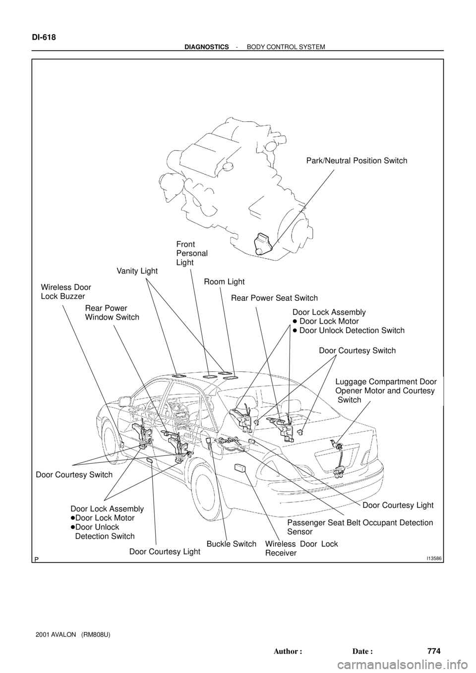
PARTS LOCATION
Page 837 of 1897
I13586
Front
Personal
Light
Vanity Light
Rear Power
Window Switch Wireless Door
Lock Buzzer
Door Lock Assembly
�Door Lock Motor
�Door Unlock
Detection Switch
Door Courtesy Light Door Courtesy Switch
Buckle Switch Room Light
Rear Power Seat Switch
Door Lock Assembly
� Door Lock Motor
� Door Unlock Detection Switch
Door Courtesy Switch
Door Courtesy Light
Luggage Compartment Door
Opener Motor and Courtesy
Switch
Passenger Seat Belt Occupant Detection
Sensor
Wireless Door Lock
Receiver
Park/Neutral Position Switch
DI-618
- DIAGNOSTICSBODY CONTROL SYSTEM
774 Author�: Date�:
2001 AVALON (RM808U)
Page 838 of 1897

PROBLEM SYMPTOMS TABLE
IGNITION SWITCH AND KEY UNLOCK WARNING SWITCH:
SymptomSuspect AreaSee page
Ignition s")
DI6LJ-01
DI-622
- DIAGNOSTICSBODY CONTROL SYSTEM
778 Author�: Date�:
2001 AVALON (RM808U)
PROBLEM SYMPTOMS TABLE
IGNITION SWITCH AND KEY UNLOCK WARNING SWITCH:
SymptomSuspect AreaSee page
Ignition switch is not set to each position.1. Ignition switch
2. Power source circuitBE-16
DI-627
Key unlock warning system does not operate.
(The buzzer does not sound when the driver's door is opened with
the ignition OFF and key inserted)
1. Power source circuit
2. Key unlock warning switch circuit
3. Door courtesy switch circuit
4. Driver door ECU
5. Multiplex communication circuit
6. Body ECU
7. Wire harnessDI-627
DI-637
DI-639
DI-676
DI-718
IN-30
IN-30
Key unlock warning system does not operate.
(The buzzer sounds when the ignition key is ACC or ON)1. Ignition switch
2. Power source circuit
3. Wire harnessBE-16
DI-627
IN-30
HEADLIGHT AND TAILLIGHT SYSTEM (USA):
SymptomSuspect AreaSee page
Only one side headlight does not light.
1. HEAD-(LH, RH) fuse
2. Headlight bulb
3. Wire harnessBE-9
-
IN-30
Headlight does not light.
1. HEAD-(LH, RH) fuse
2. Headlight control relay circuit
3. Light control switch circuit
4. Headlight bulb
5. Wire harnessBE-9
DI-635
DI-631
-
IN-30
ºLo-Beamº does not light.
1. Headlight bulb
2. Headlight dimmer switch
3. Light control switch circuit
4. Wire harness-
DI-631
DI-631
IN-30
ºHi-Beamº does not light.
1. Headlight bulb
2. Headlight dimmer switch
3. Light control switch circuit
4. Wire harness-
DI-631
DI-631
IN-30
ºFlashº does not light.1. Headlight dimmer switch
2. Wire harnessDI-631
IN-30
Only one side taillight does not light.1. Taillight bulb
2. Wire harness-
IN-30
Taillight does not light.
1. TAIL fuse
2. Taillight control relay circuit
3. Light control switch circuit
4. Body ECU
5. Wire harnessBE-9
DI-633
DI-631
IN-30
IN-30
Rear Combination light does not light.
1. Bulb
2. Light failure sensor
3. Wire harness-
BE-53
IN-30