Page 551 of 1897
P19934
Z03473
Ammeter
Voltmeter
BatteryDisconnect Wire
from Terminal B
Generator
- CHARGINGCHARGING SYSTEM
CH-3
1276 Author�: Date�:
2001 AVALON (RM808U)
�After installing a new belt, run the engine for about 5 min-
utes and recheck the belt tension.
6. VISUALLY CHECK GENERATOR WIRING AND
LISTEN FOR ABNORMAL NOISES
(a) Check that the wiring is in good condition.
(b) Check that there is no abnormal noise from the generator
while the engine is running.
7. CHECK DISCHARGE WARNING LIGHT CIRCUIT
(a) Warm up the engine and then turn it off.
(b) Turn off all accessories.
(c) Turn the ignition switch ºONº. Check that the discharge
warning light is lit.
(d) Start the engine. Check that the light goes off.
If the light does not go off as specified, troubleshoot the dis-
charge light circuit.
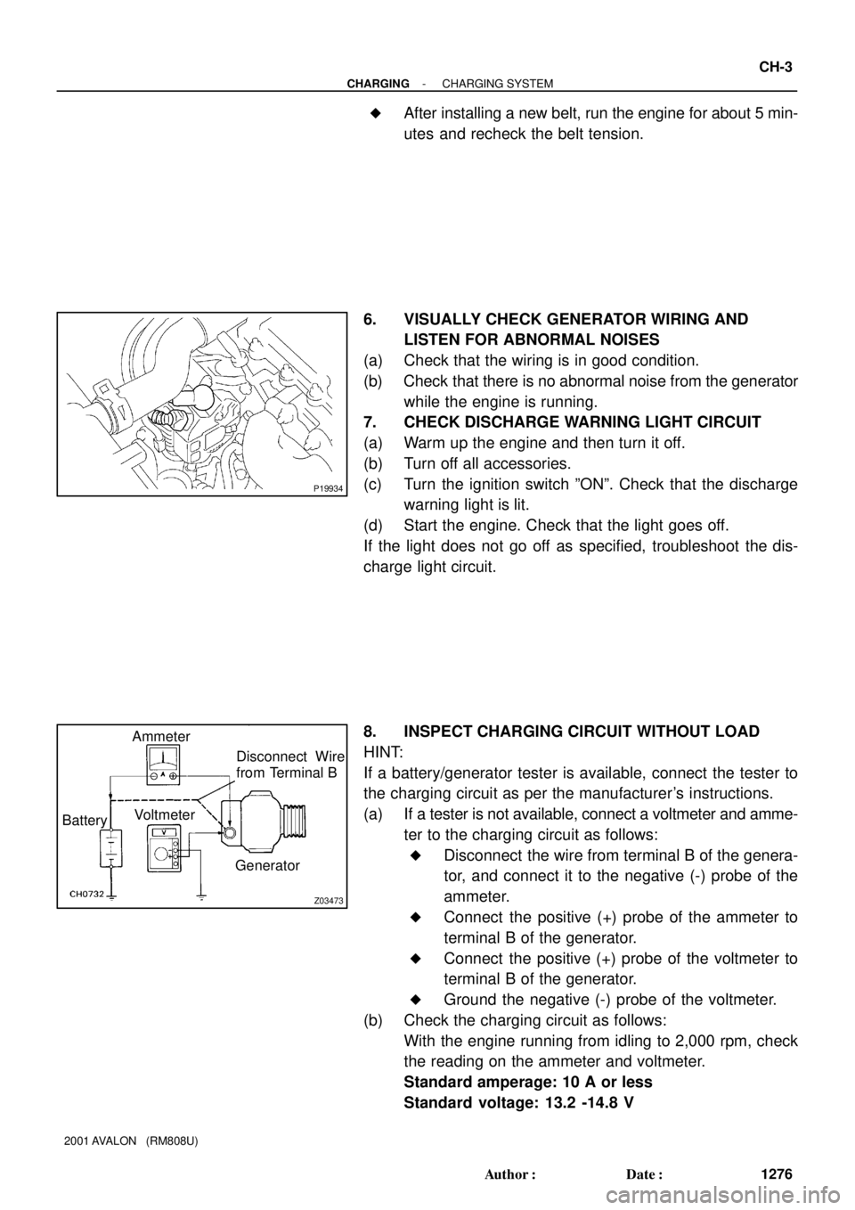
8. INSPECT CHARGING CIRCUIT WITHOUT LOAD
HINT:
If a battery/generator tester is available, connect the tester to
the charging circuit as per the manufacturer's instructions.
(a) If a tester is not available, connect a voltmeter and amme-
ter to the charging circuit as follows:
�Disconnect the wire from terminal B of the genera-
tor, and connect it to the negative (-) probe of the
ammeter.
�Connect the positive (+) probe of the ammeter to
terminal B of the generator.
�Connect the positive (+) probe of the voltmeter to
terminal B of the generator.
�Ground the negative (-) probe of the voltmeter.
(b) Check the charging circuit as follows:
With the engine running from idling to 2,000 rpm, check
the reading on the ammeter and voltmeter.
Standard amperage: 10 A or less
Standard voltage: 13.2 -14.8 V
Page 552 of 1897
P20106
Terminal F CH-4
- CHARGINGCHARGING SYSTEM
1277 Author�: Date�:
2001 AVALON (RM808U)
If the voltmeter reading is more than standard voltage, replace
the voltage regulator.
If the voltmeter reading is less than standard voltage, check the
voltage regulator and generator as follows:
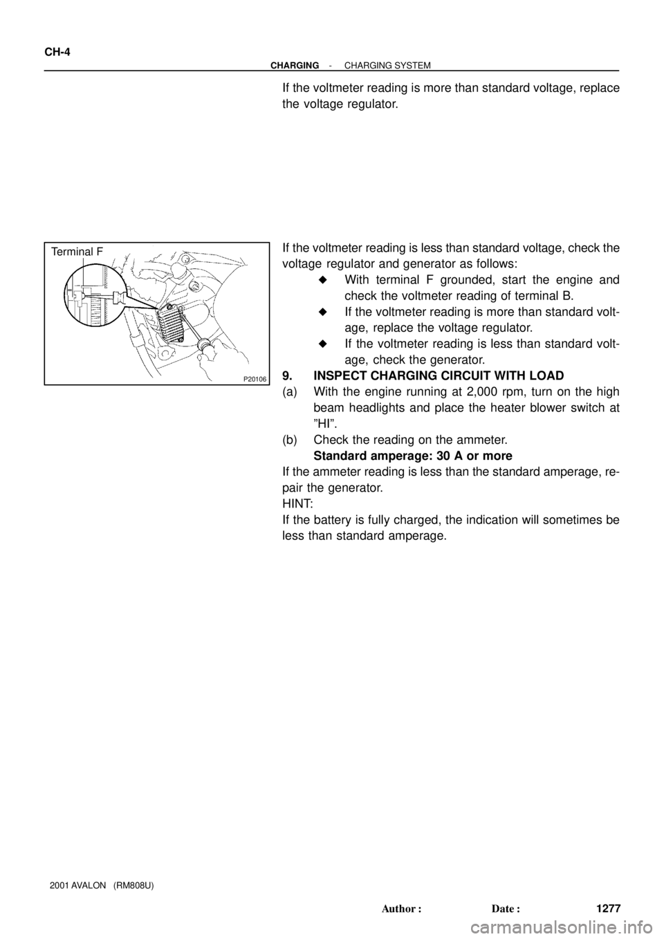
�With terminal F grounded, start the engine and
check the voltmeter reading of terminal B.
�If the voltmeter reading is more than standard volt-
age, replace the voltage regulator.
�If the voltmeter reading is less than standard volt-
age, check the generator.
9. INSPECT CHARGING CIRCUIT WITH LOAD
(a) With the engine running at 2,000 rpm, turn on the high
beam headlights and place the heater blower switch at
ºHIº.
(b) Check the reading on the ammeter.
Standard amperage: 30 A or more
If the ammeter reading is less than the standard amperage, re-
pair the generator.
HINT:
If the battery is fully charged, the indication will sometimes be
less than standard amperage.
Page 601 of 1897
- DIAGNOSTICSANTI-LOCK BRAKE SYSTEM WITH ELECTRONIC
BRAKE FORCE DISTRIBUTION (EBD)DI-239
395 Author�: Date�:
2001 AVALON (RM808U)
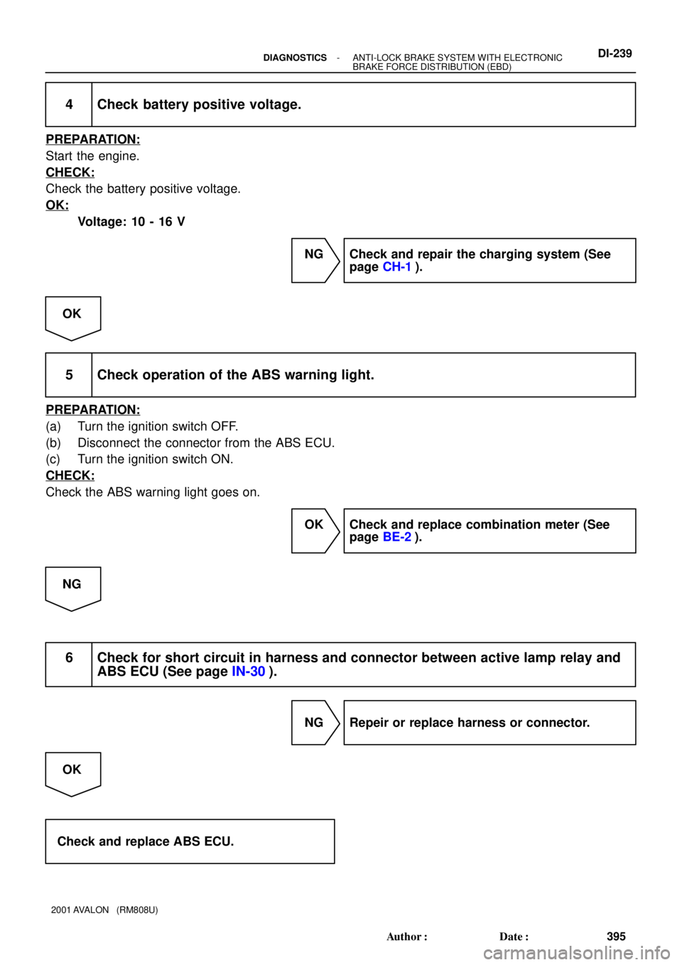
4 Check battery positive voltage.
PREPARATION:
Start the engine.
CHECK:
Check the battery positive voltage.
OK:
Voltage: 10 - 16 V
NG Check and repair the charging system (See
page CH-1).
OK
5 Check operation of the ABS warning light.
PREPARATION:
(a) Turn the ignition switch OFF.
(b) Disconnect the connector from the ABS ECU.
(c) Turn the ignition switch ON.
CHECK:
Check the ABS warning light goes on.
OK Check and replace combination meter (See
page BE-2).
NG
6 Check for short circuit in harness and connector between active lamp relay and
ABS ECU (See page IN-30).
NG Repeir or replace harness or connector.
OK
Check and replace ABS ECU.
Page 634 of 1897
BR3890
F02201
DLC1
Ts E
1
Tc
BR3904
0.13 sec. 0.12 sec.
ON
OFF
- DIAGNOSTICSANTI-LOCK BRAKE SYSTEM WITH ELECTRONIC
BRAKE FORCE DISTRIBUTION (EBD)DI-213
369 Author�: Date�:
2001 AVALON (RM808U)
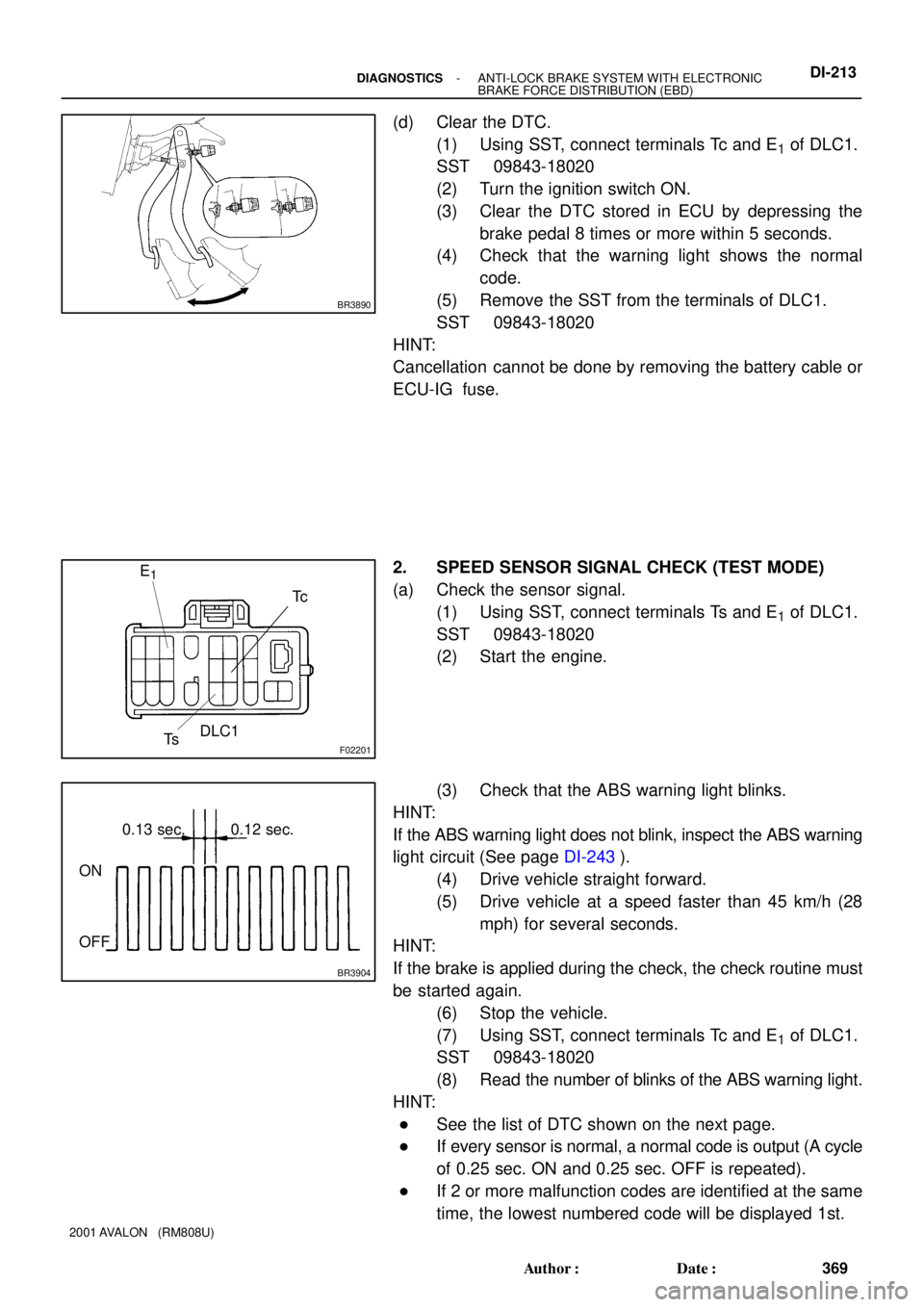
(d) Clear the DTC.
(1) Using SST, connect terminals Tc and E
1 of DLC1.
SST 09843-18020
(2) Turn the ignition switch ON.
(3) Clear the DTC stored in ECU by depressing the
brake pedal 8 times or more within 5 seconds.
(4) Check that the warning light shows the normal
code.
(5) Remove the SST from the terminals of DLC1.
SST 09843-18020
HINT:
Cancellation cannot be done by removing the battery cable or
ECU-IG fuse.
2. SPEED SENSOR SIGNAL CHECK (TEST MODE)
(a) Check the sensor signal.
(1) Using SST, connect terminals Ts and E
1 of DLC1.
SST 09843-18020
(2) Start the engine.
(3) Check that the ABS warning light blinks.
HINT:
If the ABS warning light does not blink, inspect the ABS warning
light circuit (See page DI-243).
(4) Drive vehicle straight forward.
(5) Drive vehicle at a speed faster than 45 km/h (28
mph) for several seconds.
HINT:
If the brake is applied during the check, the check routine must
be started again.
(6) Stop the vehicle.
(7) Using SST, connect terminals Tc and E
1 of DLC1.
SST 09843-18020
(8) Read the number of blinks of the ABS warning light.
HINT:
�See the list of DTC shown on the next page.
�If every sensor is normal, a normal code is output (A cycle
of 0.25 sec. ON and 0.25 sec. OFF is repeated).
�If 2 or more malfunction codes are identified at the same
time, the lowest numbered code will be displayed 1st.
Page 641 of 1897
- DIAGNOSTICSABS WITH EBD & BA & TRAC & VSC SYSTEM
DI-323
479 Author�: Date�:
2001 AVALON (RM808U)
INSPECTION PROCEDURE
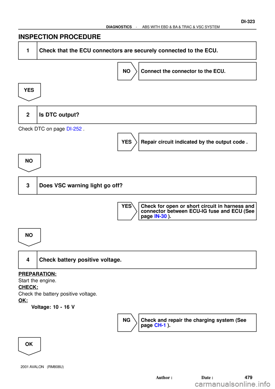
1 Check that the ECU connectors are securely connected to the ECU.
NO Connect the connector to the ECU.
YES
2 Is DTC output?
Check DTC on page DI-252.
YES Repair circuit indicated by the output code .
NO
3 Does VSC warning light go off?
YES Check for open or short circuit in harness and
connector between ECU-IG fuse and ECU (See
page IN-30).
NO
4 Check battery positive voltage.
PREPARATION:
Start the engine.
CHECK:
Check the battery positive voltage.
OK:
Voltage: 10 - 16 V
NG Check and repair the charging system (See
page CH-1).
OK
Page 644 of 1897
DI-320
- DIAGNOSTICSABS WITH EBD & BA & TRAC & VSC SYSTEM
476 Author�: Date�:
2001 AVALON (RM808U)
INSPECTION PROCEDURE
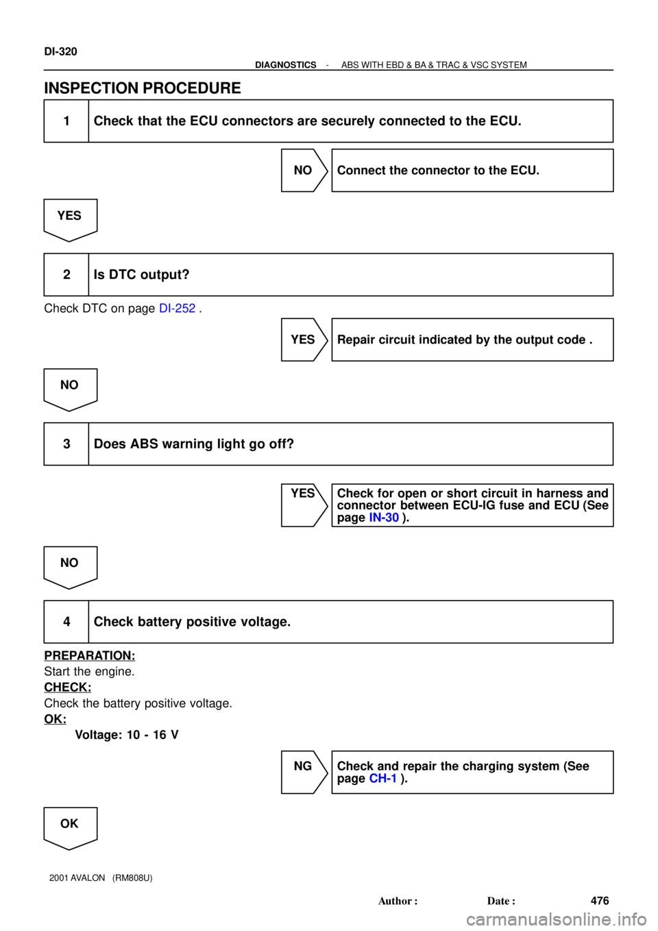
1 Check that the ECU connectors are securely connected to the ECU.
NO Connect the connector to the ECU.
YES
2 Is DTC output?
Check DTC on page DI-252.
YES Repair circuit indicated by the output code .
NO
3 Does ABS warning light go off?
YES Check for open or short circuit in harness and
connector between ECU-IG fuse and ECU (See
page IN-30).
NO
4 Check battery positive voltage.
PREPARATION:
Start the engine.
CHECK:
Check the battery positive voltage.
OK:
Voltage: 10 - 16 V
NG Check and repair the charging system (See
page CH-1).
OK
Page 727 of 1897
F02201
DLC1
TsTc E
1
BR3904
0.13 sec. 0.13 sec.
ON
OFF
BR3893
Malfunction Code (Example Code 72, 76)
72 67
ON
OFF
0.5 sec. 0.5 sec. 0.5 sec. 0.5 sec.1.5 sec.
2.5 sec.4 sec.
Repeat
- DIAGNOSTICSABS WITH EBD & BA & TRAC & VSC SYSTEM
DI-255
411 Author�: Date�:
2001 AVALON (RM808U)
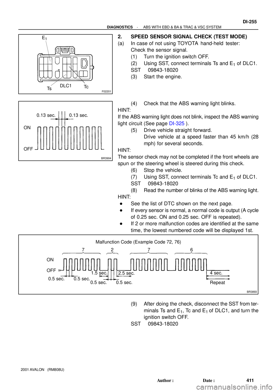
2. SPEED SENSOR SIGNAL CHECK (TEST MODE)
(a) In case of not using TOYOTA hand-held tester:
Check the sensor signal.
(1) Turn the ignition switch OFF.
(2) Using SST, connect terminals Ts and E
1 of DLC1.
SST 09843-18020
(3) Start the engine.
(4) Check that the ABS warning light blinks.
HINT:
If the ABS warning light does not blink, inspect the ABS warning
light circuit (See page DI-325).
(5) Drive vehicle straight forward.
Drive vehicle at a speed faster than 45 km/h (28
mph) for several seconds.
HINT:
The sensor check may not be completed if the front wheels are
spun or the steering wheel is steered during this check.
(6) Stop the vehicle.
(7) Using SST, connect terminals Tc and E
1 of DLC1.
SST 09843-18020
(8) Read the number of blinks of the ABS warning light.
HINT:
�See the list of DTC shown on the next page.
�If every sensor is normal, a normal code is output (A cycle
of 0.25 sec. ON and 0.25 sec. OFF is repeated).
�If 2 or more malfunction codes are identified at the same
time, the lowest numbered code will be displayed 1st.
(9) After doing the check, disconnect the SST from ter-
minals Ts and E
1, Tc and E1 of DLC1, and turn the
ignition switch OFF.
SST 09843-18020
Page 771 of 1897
DI02E-08
FI0534
F07887DLC3
TOYOTA hand-held tester
DI-160
- DIAGNOSTICSAUTOMATIC TRANSAXLE
316 Author�: Date�:
2001 AVALON (RM808U)
PRE-CHECK
1. DIAGNOSIS SYSTEM
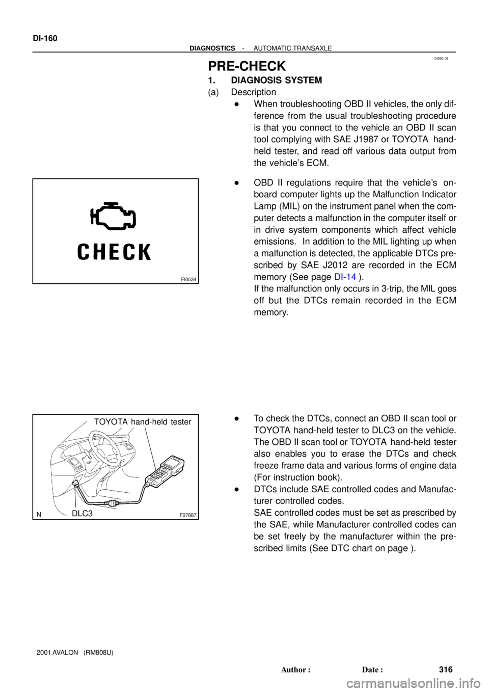
(a) Description
�When troubleshooting OBD II vehicles, the only dif-
ference from the usual troubleshooting procedure
is that you connect to the vehicle an OBD II scan
tool complying with SAE J1987 or TOYOTA hand-
held tester, and read off various data output from
the vehicle's ECM.
�OBD II regulations require that the vehicle's on-
board computer lights up the Malfunction Indicator
Lamp (MIL) on the instrument panel when the com-
puter detects a malfunction in the computer itself or
in drive system components which affect vehicle
emissions. In addition to the MIL lighting up when
a malfunction is detected, the applicable DTCs pre-
scribed by SAE J2012 are recorded in the ECM
memory (See page DI-14).
If the malfunction only occurs in 3-trip, the MIL goes
off but the DTCs remain recorded in the ECM
memory.
�To check the DTCs, connect an OBD II scan tool or
TOYOTA hand-held tester to DLC3 on the vehicle.
The OBD II scan tool or TOYOTA hand-held tester
also enables you to erase the DTCs and check
freeze frame data and various forms of engine data
(For instruction book).
�DTCs include SAE controlled codes and Manufac-
turer controlled codes.
SAE controlled codes must be set as prescribed by
the SAE, while Manufacturer controlled codes can
be set freely by the manufacturer within the pre-
scribed limits (See DTC chart on page ).