Page 677 of 1897

- DIAGNOSTICSABS WITH EBD & BA & TRAC & VSC SYSTEM
DI-295
451 Author�: Date�:
2001 AVALON (RM808U)
DTCC1237 / 37 Wrong Number of Teeth at 1 of 4 Wheels
CIRCUIT DESCRIPTION
DTC No.DTC Detecting ConditionTrouble Area
C1237 / 37
Detection of any of conditions from 1. through 4.:
1. When the ignition switch is ON, the speed difference
between the rear right and rear left wheels is 5 km/h
(3mph) or more (vehicle speed: 100 km/h (62 mph) or
less).
2. When the ignition switch is ON, the slip difference be-
tween the reference wheel and any other wheels is 6 %
or more (vehicle speed: 100 km/h (62 mph) or more).
3. Continuous ABS control for 60 sec. or more.
4. Interference on 1 or more wheels for 20 sec. with the
brake pedal depressed, or for 5 sec. when the brake
pedal is not depressed.
�Tire size
�Speed sensor rotor
INSPECTION PROCEDURE
1 Check tire size.
NG Replace tires so that all 4 tires are the same in
size.
OK
2 Check sensor rotor (See page DI-267).
NG Replace speed sensor rotor.
OK
3 Check speed sensor (See page DI-267).
NG Replace speed sensor.
OK
DI6O5-01
Page 719 of 1897

DI6NT-03
DI-258
- DIAGNOSTICSABS WITH EBD & BA & TRAC & VSC SYSTEM
414 Author�: Date�:
2001 AVALON (RM808U)
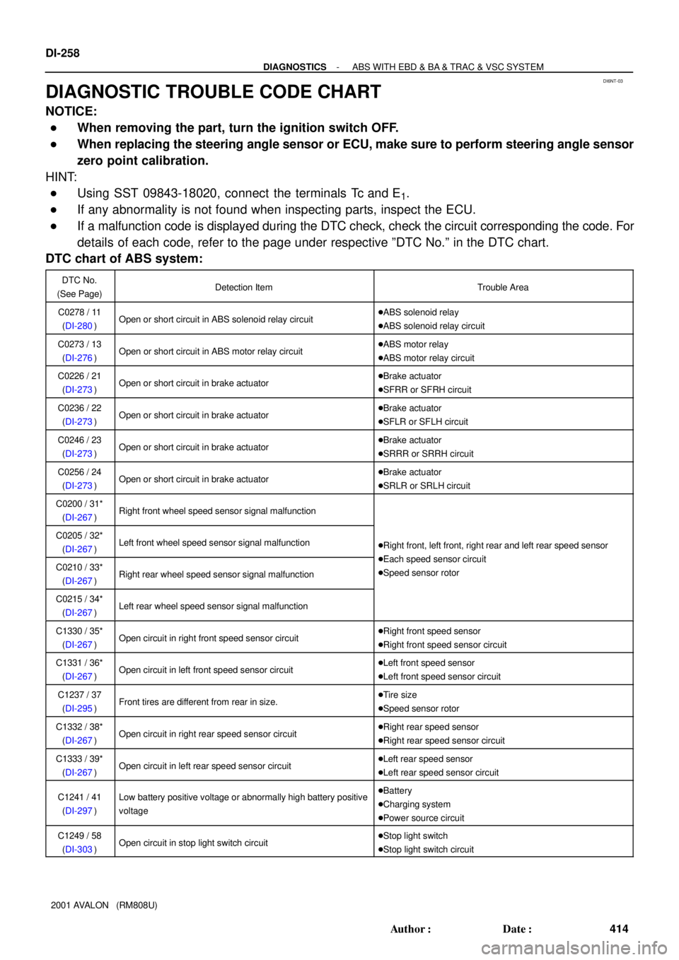
DIAGNOSTIC TROUBLE CODE CHART
NOTICE:
�When removing the part, turn the ignition switch OFF.
�When replacing the steering angle sensor or ECU, make sure to perform steering angle sensor
zero point calibration.
HINT:
�Using SST 09843-18020, connect the terminals Tc and E1.
�If any abnormality is not found when inspecting parts, inspect the ECU.
�If a malfunction code is displayed during the DTC check, check the circuit corresponding the code. For
details of each code, refer to the page under respective ºDTC No.º in the DTC chart.
DTC chart of ABS system:
DTC No.
(See Page)Detection ItemTrouble Area
C0278 / 11
(DI-280)Open or short circuit in ABS solenoid relay circuit�ABS solenoid relay
�ABS solenoid relay circuit
C0273 / 13
(DI-276)Open or short circuit in ABS motor relay circuit�ABS motor relay
�ABS motor relay circuit
C0226 / 21
(DI-273)Open or short circuit in brake actuator�Brake actuator
�SFRR or SFRH circuit
C0236 / 22
(DI-273)Open or short circuit in brake actuator�Brake actuator
�SFLR or SFLH circuit
C0246 / 23
(DI-273)Open or short circuit in brake actuator�Brake actuator
�SRRR or SRRH circuit
C0256 / 24
(DI-273)Open or short circuit in brake actuator�Brake actuator
�SRLR or SRLH circuit
C0200 / 31*
(DI-267)Right front wheel speed sensor signal malfunction
C0205 / 32*
(DI-267)Left front wheel speed sensor signal malfunction�Right front, left front, right rear and left rear speed sensor
Eh d i itC0210 / 33*
(DI-267)Right rear wheel speed sensor signal malfunction
�Each speed sensor circuit
�Speed sensor rotor
C0215 / 34*
(DI-267)Left rear wheel speed sensor signal malfunction
C1330 / 35*
(DI-267)Open circuit in right front speed sensor circuit�Right front speed sensor
�Right front speed sensor circuit
C1331 / 36*
(DI-267)Open circuit in left front speed sensor circuit�Left front speed sensor
�Left front speed sensor circuit
C1237 / 37
(DI-295)Front tires are different from rear in size.�Tire size
�Speed sensor rotor
C1332 / 38*
(DI-267)Open circuit in right rear speed sensor circuit�Right rear speed sensor
�Right rear speed sensor circuit
C1333 / 39*
(DI-267)Open circuit in left rear speed sensor circuit�Left rear speed sensor
�Left rear speed sensor circuit
C1241 / 41
(DI-297)Low battery positive voltage or abnormally high battery positive
voltage�Battery
�Charging system
�Power source circuit
C1249 / 58
(DI-303)Open circuit in stop light switch circuit�Stop light switch
�Stop light switch circuit
Page 723 of 1897
DI6NU-01
F07883
ABS Warning Light
VSC Warning Light
VSC OFF Indicator Light
SLIP Indicator Light
BRAKE Warning Light
DLC2Rear Speed Sensor
Sensor Rotor
Brake Actuator
ABS & BA & TRAC & VSC ECU
VSC OFF Switch Front Speed Sensor
DLC1
ABS Solenoid RelayABS Motor Relay
Room R/B No. 8 Engine
Precharge PumpMaster Cylinder
Pressure Sensor
Parking Brake Switch
Stop Light Switch
Translate ECU
Front Speed Sensor
Sensor Rotor
Sensor Rotor
Rear Speed Sensor
DLC3
Steering Angle Sensor
Yaw Rate Sensor
(Including Deceleration Sensor)
Active Lamp Relay
- DIAGNOSTICSABS WITH EBD & BA & TRAC & VSC SYSTEM
DI-261
417 Author�: Date�:
2001 AVALON (RM808U)
PARTS LOCATION
Page 848 of 1897

I13617
Cruise Control ECU
4 3
3
W-B8 Stop Light Switch
4Cruise Control Actuator
13
II1
IJJ9
J/CL
9P-B P-B G-B GNDL
AC4
S4
C15
W-B II1
- DIAGNOSTICSCRUISE CONTROL SYSTEM
DI-563
719 Author�: Date�:
2001 AVALON (RM808U)
DTC 12 Actuator Magnetic Clutch Circuit
CIRCUIT DESCRIPTION
This circuit turns on the magnetic clutch inside the actuator during cruise control operation according to the
signal from the ECU. If a malfunction occurs in the actuator or speed sensor, etc. during cruise control opera-
tion, the rotor shaft between the motor and control plate is released.
When the brake pedal is depressed, the stop light switch turns on, supplying electrical power to the stop light.
Power supply to the magnetic clutch is mechanically cut and the magnetic clutch is turned OFF.
When driving downhill, if the vehicle speed exceeds the set speed by 15 km/h (9 mph), the ECU turns the
safety magnet clutch OFF. If the vehicle speed later drops to within 10 km/h (6 mph), cruise control at the
set speed is resumed.
DTC No.Detection ItemTrouble Area
12Short in actuator magnetic clutch circuit.
Open (0.8 sec.) in actuator magnetic clutch circuit.
�STOP Fuse
�Stop light switch
�Actuator magnetic clutch
�Harness or connector between cruise control ECU and
actuator magnetic clutch, actuator magnetic clutch and body
ground
�Cruise control ECU
WIRING DIAGRAM
DI08N-15
Page 1847 of 1897

SA0VY-02
FA1535
SST
W03093
W03142
F07389
SA-16
- SUSPENSION AND AXLEFRONT DRIVE SHAFT
1350 Author�: Date�:
2001 AVALON (RM808U)
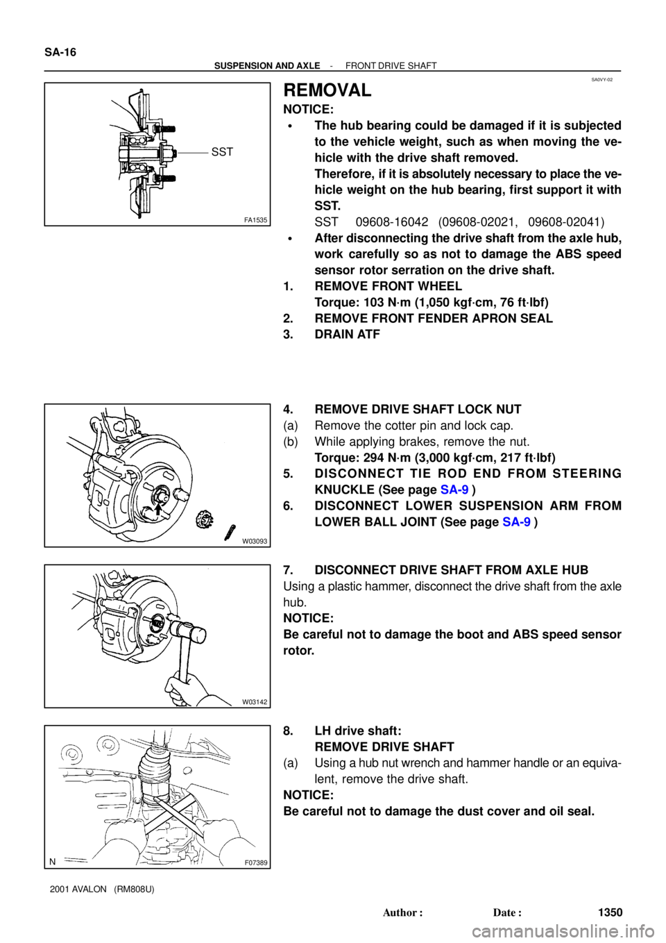
REMOVAL
NOTICE:
�The hub bearing could be damaged if it is subjected
to the vehicle weight, such as when moving the ve-
hicle with the drive shaft removed.
Therefore, if it is absolutely necessary to place the ve-
hicle weight on the hub bearing, first support it with
SST.
SST 09608-16042 (09608-02021, 09608-02041)
�After disconnecting the drive shaft from the axle hub,
work carefully so as not to damage the ABS speed
sensor rotor serration on the drive shaft.
1. REMOVE FRONT WHEEL
Torque: 103 N´m (1,050 kgf´cm, 76 ft´lbf)
2. REMOVE FRONT FENDER APRON SEAL
3. DRAIN ATF
4. REMOVE DRIVE SHAFT LOCK NUT
(a) Remove the cotter pin and lock cap.
(b) While applying brakes, remove the nut.
Torque: 294 N´m (3,000 kgf´cm, 217 ft´lbf)
5. DISCONNECT TIE ROD END FROM STEERING
KNUCKLE (See page SA-9)
6. DISCONNECT LOWER SUSPENSION ARM FROM
LOWER BALL JOINT (See page SA-9)
7. DISCONNECT DRIVE SHAFT FROM AXLE HUB
Using a plastic hammer, disconnect the drive shaft from the axle
hub.
NOTICE:
Be careful not to damage the boot and ABS speed sensor
rotor.
8. LH drive shaft:
REMOVE DRIVE SHAFT
(a) Using a hub nut wrench and hammer handle or an equiva-
lent, remove the drive shaft.
NOTICE:
Be careful not to damage the dust cover and oil seal.